DC Motor: Components, Operation, and Electromagnetic Principles
VerifiedAdded on 2023/06/04
|14
|4137
|338
Report
AI Summary
This report provides a detailed explanation of the design and working principles of a DC motor. It starts by outlining the main components, including the magnet, armature coil, split ring commutator, brushes, and battery. The report then delves into the operational principles, emphasizing Faraday's Law of Electromagnetic Induction (both first and second laws) and Lenz's Law, which explain the relationship between electrical and magnetic fields and the generation of induced EMF. The concept of back EMF and its role in regulating motor speed and current is also discussed. Furthermore, the report explores Lorentz's Law, which governs the force experienced by a current-carrying conductor in a magnetic field, and its application in the DC motor's operation. The analysis includes the use of Fleming's right-hand rule to determine the direction of induced EMF. The report uses figures and equations to illustrate the concepts, providing a comprehensive understanding of the DC motor's functionality.
ELECTROMAGNETISM
YOUR NAME
ROLL NUMBER
DATE OF SUBMISSION
YOUR NAME
ROLL NUMBER
DATE OF SUBMISSION
Paraphrase This Document
Need a fresh take? Get an instant paraphrase of this document with our AI Paraphraser
1 Solutions PH12-13 to PH11/12-1/2/3/4/5/6/7
1.1 DC motor Design
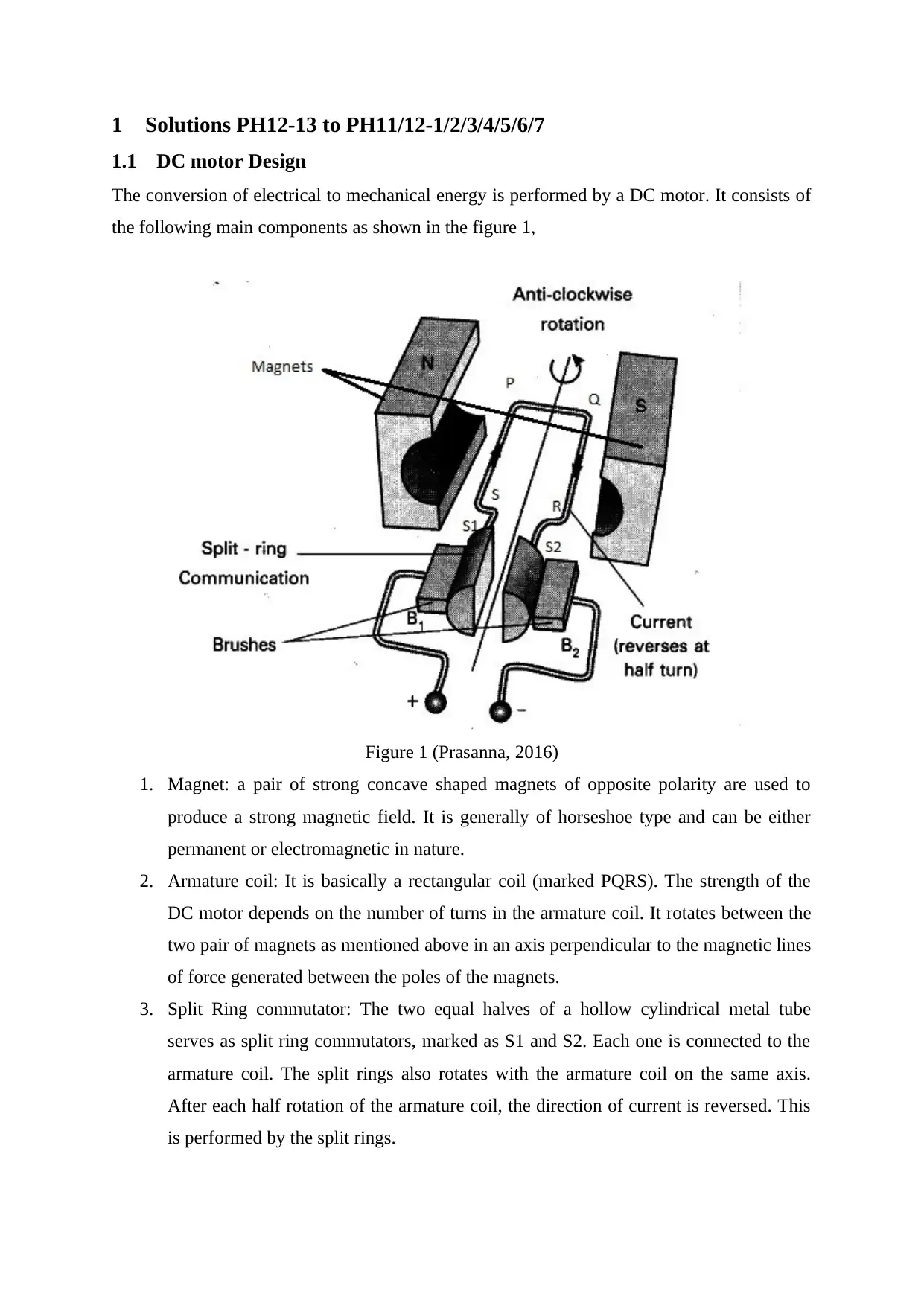
The conversion of electrical to mechanical energy is performed by a DC motor. It consists of
the following main components as shown in the figure 1,
Figure 1 (Prasanna, 2016)
1. Magnet: a pair of strong concave shaped magnets of opposite polarity are used to
produce a strong magnetic field. It is generally of horseshoe type and can be either
permanent or electromagnetic in nature.
2. Armature coil: It is basically a rectangular coil (marked PQRS). The strength of the
DC motor depends on the number of turns in the armature coil. It rotates between the
two pair of magnets as mentioned above in an axis perpendicular to the magnetic lines
of force generated between the poles of the magnets.
3. Split Ring commutator: The two equal halves of a hollow cylindrical metal tube
serves as split ring commutators, marked as S1 and S2. Each one is connected to the
armature coil. The split rings also rotates with the armature coil on the same axis.
After each half rotation of the armature coil, the direction of current is reversed. This
is performed by the split rings.
1.1 DC motor Design
The conversion of electrical to mechanical energy is performed by a DC motor. It consists of
the following main components as shown in the figure 1,
Figure 1 (Prasanna, 2016)
1. Magnet: a pair of strong concave shaped magnets of opposite polarity are used to
produce a strong magnetic field. It is generally of horseshoe type and can be either
permanent or electromagnetic in nature.
2. Armature coil: It is basically a rectangular coil (marked PQRS). The strength of the
DC motor depends on the number of turns in the armature coil. It rotates between the
two pair of magnets as mentioned above in an axis perpendicular to the magnetic lines
of force generated between the poles of the magnets.
3. Split Ring commutator: The two equal halves of a hollow cylindrical metal tube
serves as split ring commutators, marked as S1 and S2. Each one is connected to the
armature coil. The split rings also rotates with the armature coil on the same axis.
After each half rotation of the armature coil, the direction of current is reversed. This
is performed by the split rings.
4. Brushes: Continuous current needs to be supplied to the armature coil, but it is in
motion. So, in order to supply current continuously to the rotating coil via the split
rings, graphite or carbon contacts are used called as brushes (marked as B1 and B2).
After each half rotation, the connection of the split rings with the brushes reverses.
This means that if S1 is connected to the brush B1 and S2 is connected to the brush
B2, then in the second half rotation, S1 will be connected to B2 while S2 will be
connected to B1.
5. Battery: a combination of cells is called a battery. The battery is connected to the
brushes directly, current from which is then transferred to the armature coil through
the split rings.
6. Case: to protect all the internal components from the external environment in order to
avoid any damage in the working of the DC motor a hard case is used that covers all
the internal components. The necessary probes and the shaft from the armature coil is
taken out from it. Bearings may be used in order to reduce the friction of the shaft.
1.2 Principle of operation
1.2.1 Faraday’s Law of Electromagnetic Induction
The relation of the electrical field with the magnetic field is very well demonstrated with the
help of this law. The DC motor works on this principle. Faraday proposed two laws,
Faraday’s first and second law of electromagnetic induction (Friedl, n.d.).
1.2.1.1 Faraday’s first Law of Electromagnetic Induction
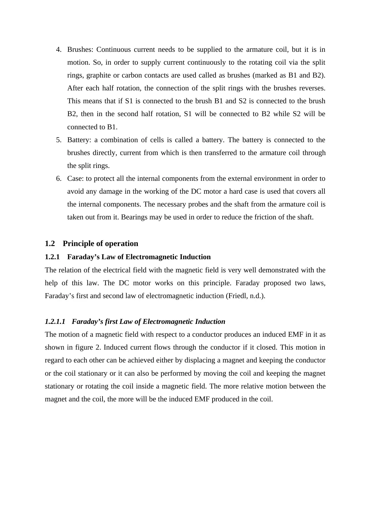
The motion of a magnetic field with respect to a conductor produces an induced EMF in it as
shown in figure 2. Induced current flows through the conductor if it closed. This motion in
regard to each other can be achieved either by displacing a magnet and keeping the conductor
or the coil stationary or it can also be performed by moving the coil and keeping the magnet
stationary or rotating the coil inside a magnetic field. The more relative motion between the
magnet and the coil, the more will be the induced EMF produced in the coil.
motion. So, in order to supply current continuously to the rotating coil via the split
rings, graphite or carbon contacts are used called as brushes (marked as B1 and B2).
After each half rotation, the connection of the split rings with the brushes reverses.
This means that if S1 is connected to the brush B1 and S2 is connected to the brush
B2, then in the second half rotation, S1 will be connected to B2 while S2 will be
connected to B1.
5. Battery: a combination of cells is called a battery. The battery is connected to the
brushes directly, current from which is then transferred to the armature coil through
the split rings.
6. Case: to protect all the internal components from the external environment in order to
avoid any damage in the working of the DC motor a hard case is used that covers all
the internal components. The necessary probes and the shaft from the armature coil is
taken out from it. Bearings may be used in order to reduce the friction of the shaft.
1.2 Principle of operation
1.2.1 Faraday’s Law of Electromagnetic Induction
The relation of the electrical field with the magnetic field is very well demonstrated with the
help of this law. The DC motor works on this principle. Faraday proposed two laws,
Faraday’s first and second law of electromagnetic induction (Friedl, n.d.).
1.2.1.1 Faraday’s first Law of Electromagnetic Induction
The motion of a magnetic field with respect to a conductor produces an induced EMF in it as
shown in figure 2. Induced current flows through the conductor if it closed. This motion in
regard to each other can be achieved either by displacing a magnet and keeping the conductor
or the coil stationary or it can also be performed by moving the coil and keeping the magnet
stationary or rotating the coil inside a magnetic field. The more relative motion between the
magnet and the coil, the more will be the induced EMF produced in the coil.
⊘ This is a preview!⊘
Do you want full access?
Subscribe today to unlock all pages.
Trusted by 1+ million students worldwide
Figure 2 (Ghosh, 2018)
1.2.1.2 Faraday’s second Law of Electromagnetic Induction
It states that the induced EMF generated in the coil is equal to the rate of change of magnetic
flux linkage linked with the coil. In DC motor the armature coil carrying the current is moved
in the magnetic field produced by the magnets. This process generates an induced EMF
within the coil.
Let a conductor be moving in the magnetic field such that flux linkage with the coil =NΦ1 (in
weber). Here, N is motor’s speed and Φ is the magnetic flux. This is the initial flux linkage.
Now, the final flux linkage with the coil = NΦ2.
The difference in the flux linkage = NΦ1 – NΦ2 =N (Φ1 – Φ1) = Φ (where, Φ = Φ1 – Φ1).
Therefore, Difference in the flux linkage =NΦ.
The rate of change of magnetic flux linkage = NΦ/t.
Finding out the derivation, rate of change of magnetic flux linkages =N (d Φ/d t).
Therefore, the magnitude of EMF generated in the armature coil of the DC motor is equal to
the rate of change of magnetic flux linkages (Lucas, 2016), (Ghosh, 2018).
1.2.2 Lenz’s Law
According to it, the EMF induced in the armature coil is such that it is direction is opposite to
the cause producing it. Formulating this law we get,
E = – N (d Φ/d t) (in volts). The opposite nature of the induced EMF with respect to the
change in magnetic flux linkage is reflected by the negative sign (Encyclopaedia Britannica,
n.d.), (Electrical4u, 2018). The current flowing through the arm SP tends to move the arm
upwards, while the current flowing through the arm QR tends to move it downwards, when
Paraphrase This Document
Need a fresh take? Get an instant paraphrase of this document with our AI Paraphraser
the positive potential is applied on S1 and the negative on S2 as shown in the figure 5. This
makes the armature coil to move. According to Lenz’s Law, there is an induced EMF
developed that tends to oppose the cause producing it, so the cause here is the armature coil
current in both the arms, so the bac EMF induced in the arm SP would be negative of the coil
current and is given as E = – N (d Φ/d t) (in volts). An induced EMF is also developed in the
arm QR in the direction opposite to the coil current in QR and is of the magnitude E = – N (d
Φ/d t) (in volts). These two induced EMF would generate an induced current because the
circuit is closed and tends to act as a couple, opposite to the couple generated by the armature
coil currents which was rotating the motor. Similarly, when the coil completes one complete
rotation and the polarity reverses, the direction of the arm current also reverses as shown in
the figure 6 but the nature of the induced current remains same, that is opposite to the
armature arm currents and acts opposite to them as discussed just now. The electrical input
given in the form of armature coil current is partially dissipated as heat, Eddy current, sound
and other forms of losses along with this induced current because it opposes the cause
producing it which is responsible to rotate the coil. Some part is stored in the magnetic field.
This is obeying the Law of conservation of Energy (Magnet Academy, 2015).
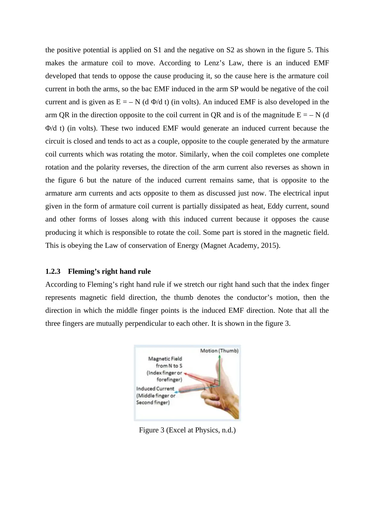
1.2.3 Fleming’s right hand rule
According to Fleming’s right hand rule if we stretch our right hand such that the index finger
represents magnetic field direction, the thumb denotes the conductor’s motion, then the
direction in which the middle finger points is the induced EMF direction. Note that all the
three fingers are mutually perpendicular to each other. It is shown in the figure 3.
Figure 3 (Excel at Physics, n.d.)
makes the armature coil to move. According to Lenz’s Law, there is an induced EMF
developed that tends to oppose the cause producing it, so the cause here is the armature coil
current in both the arms, so the bac EMF induced in the arm SP would be negative of the coil
current and is given as E = – N (d Φ/d t) (in volts). An induced EMF is also developed in the
arm QR in the direction opposite to the coil current in QR and is of the magnitude E = – N (d
Φ/d t) (in volts). These two induced EMF would generate an induced current because the
circuit is closed and tends to act as a couple, opposite to the couple generated by the armature
coil currents which was rotating the motor. Similarly, when the coil completes one complete
rotation and the polarity reverses, the direction of the arm current also reverses as shown in
the figure 6 but the nature of the induced current remains same, that is opposite to the
armature arm currents and acts opposite to them as discussed just now. The electrical input
given in the form of armature coil current is partially dissipated as heat, Eddy current, sound
and other forms of losses along with this induced current because it opposes the cause
producing it which is responsible to rotate the coil. Some part is stored in the magnetic field.
This is obeying the Law of conservation of Energy (Magnet Academy, 2015).
1.2.3 Fleming’s right hand rule
According to Fleming’s right hand rule if we stretch our right hand such that the index finger
represents magnetic field direction, the thumb denotes the conductor’s motion, then the
direction in which the middle finger points is the induced EMF direction. Note that all the
three fingers are mutually perpendicular to each other. It is shown in the figure 3.
Figure 3 (Excel at Physics, n.d.)
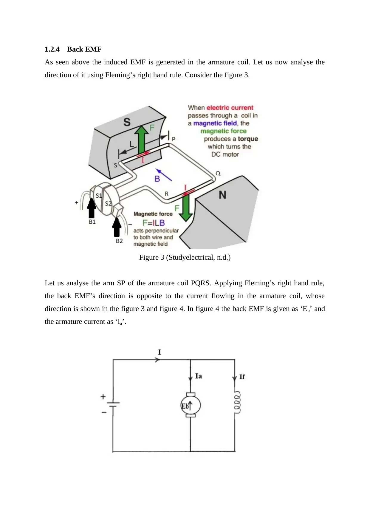
1.2.4 Back EMF
As seen above the induced EMF is generated in the armature coil. Let us now analyse the
direction of it using Fleming’s right hand rule. Consider the figure 3.
Figure 3 (Studyelectrical, n.d.)
Let us analyse the arm SP of the armature coil PQRS. Applying Fleming’s right hand rule,
the back EMF’s direction is opposite to the current flowing in the armature coil, whose
direction is shown in the figure 3 and figure 4. In figure 4 the back EMF is given as ‘Eb’ and
the armature current as ‘Ia’.
⊘ This is a preview!⊘
Do you want full access?
Subscribe today to unlock all pages.
Trusted by 1+ million students worldwide
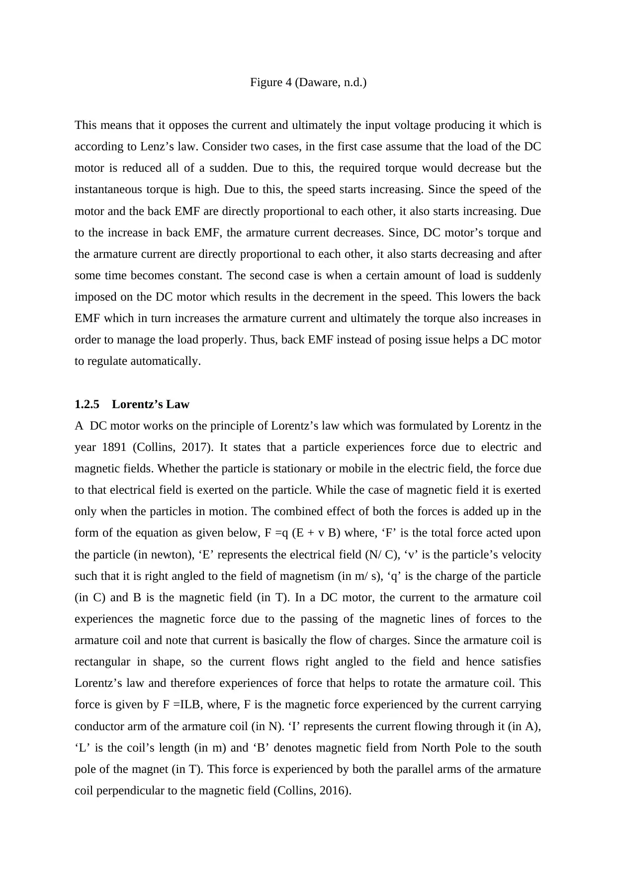
Figure 4 (Daware, n.d.)
This means that it opposes the current and ultimately the input voltage producing it which is
according to Lenz’s law. Consider two cases, in the first case assume that the load of the DC
motor is reduced all of a sudden. Due to this, the required torque would decrease but the
instantaneous torque is high. Due to this, the speed starts increasing. Since the speed of the
motor and the back EMF are directly proportional to each other, it also starts increasing. Due
to the increase in back EMF, the armature current decreases. Since, DC motor’s torque and
the armature current are directly proportional to each other, it also starts decreasing and after
some time becomes constant. The second case is when a certain amount of load is suddenly
imposed on the DC motor which results in the decrement in the speed. This lowers the back
EMF which in turn increases the armature current and ultimately the torque also increases in
order to manage the load properly. Thus, back EMF instead of posing issue helps a DC motor
to regulate automatically.
1.2.5 Lorentz’s Law
A DC motor works on the principle of Lorentz’s law which was formulated by Lorentz in the
year 1891 (Collins, 2017). It states that a particle experiences force due to electric and
magnetic fields. Whether the particle is stationary or mobile in the electric field, the force due
to that electrical field is exerted on the particle. While the case of magnetic field it is exerted
only when the particles in motion. The combined effect of both the forces is added up in the
form of the equation as given below, F =q (E + v B) where, ‘F’ is the total force acted upon
the particle (in newton), ‘E’ represents the electrical field (N/ C), ‘v’ is the particle’s velocity
such that it is right angled to the field of magnetism (in m/ s), ‘q’ is the charge of the particle
(in C) and B is the magnetic field (in T). In a DC motor, the current to the armature coil
experiences the magnetic force due to the passing of the magnetic lines of forces to the
armature coil and note that current is basically the flow of charges. Since the armature coil is
rectangular in shape, so the current flows right angled to the field and hence satisfies
Lorentz’s law and therefore experiences of force that helps to rotate the armature coil. This
force is given by F =ILB, where, F is the magnetic force experienced by the current carrying
conductor arm of the armature coil (in N). ‘I’ represents the current flowing through it (in A),
‘L’ is the coil’s length (in m) and ‘B’ denotes magnetic field from North Pole to the south
pole of the magnet (in T). This force is experienced by both the parallel arms of the armature
coil perpendicular to the magnetic field (Collins, 2016).
Paraphrase This Document
Need a fresh take? Get an instant paraphrase of this document with our AI Paraphraser
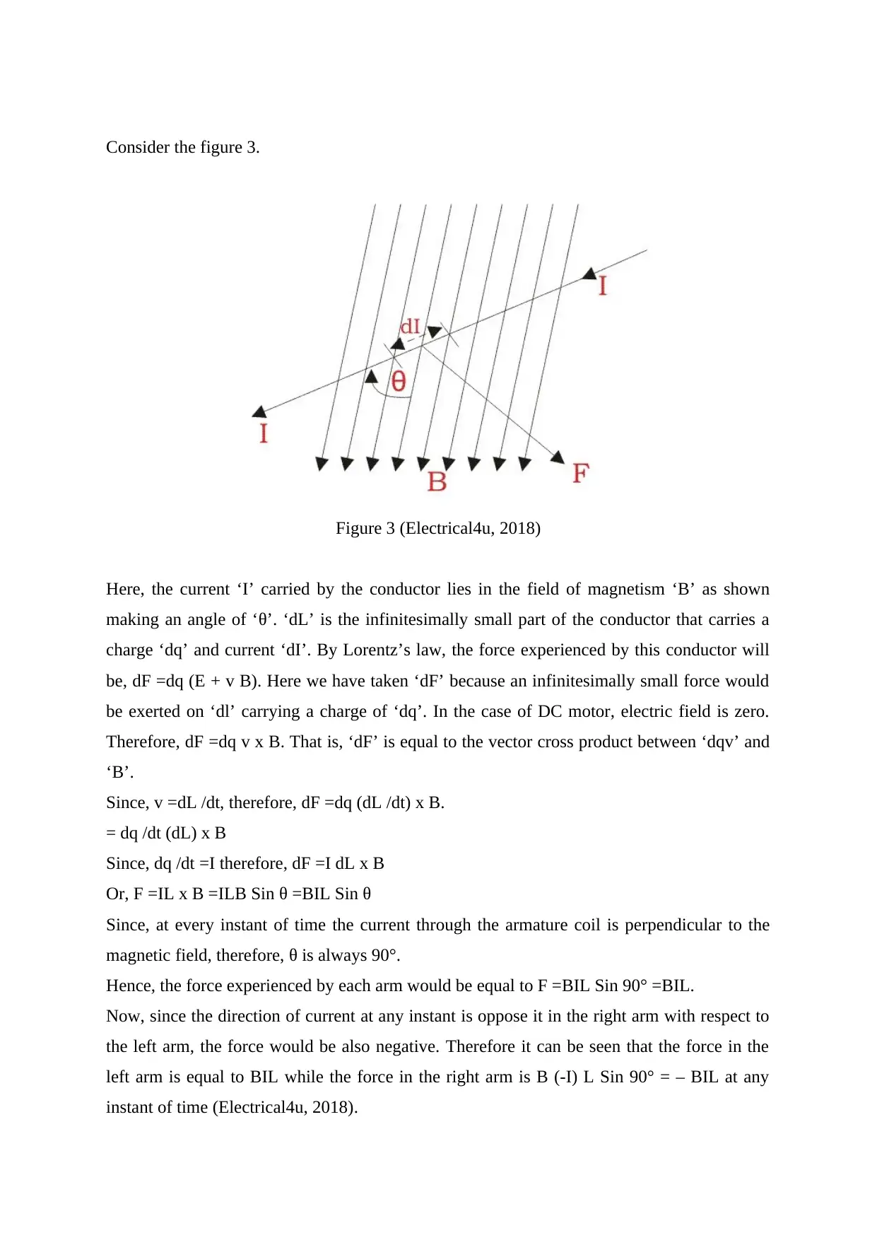
Consider the figure 3.
Figure 3 (Electrical4u, 2018)
Here, the current ‘I’ carried by the conductor lies in the field of magnetism ‘B’ as shown
making an angle of ‘θ’. ‘dL’ is the infinitesimally small part of the conductor that carries a
charge ‘dq’ and current ‘dI’. By Lorentz’s law, the force experienced by this conductor will
be, dF =dq (E + v B). Here we have taken ‘dF’ because an infinitesimally small force would
be exerted on ‘dl’ carrying a charge of ‘dq’. In the case of DC motor, electric field is zero.
Therefore, dF =dq v x B. That is, ‘dF’ is equal to the vector cross product between ‘dqv’ and
‘B’.
Since, v =dL /dt, therefore, dF =dq (dL /dt) x B.
= dq /dt (dL) x B
Since, dq /dt =I therefore, dF =I dL x B
Or, F =IL x B =ILB Sin θ =BIL Sin θ
Since, at every instant of time the current through the armature coil is perpendicular to the
magnetic field, therefore, θ is always 90°.
Hence, the force experienced by each arm would be equal to F =BIL Sin 90° =BIL.
Now, since the direction of current at any instant is oppose it in the right arm with respect to
the left arm, the force would be also negative. Therefore it can be seen that the force in the
left arm is equal to BIL while the force in the right arm is B (-I) L Sin 90° = – BIL at any
instant of time (Electrical4u, 2018).
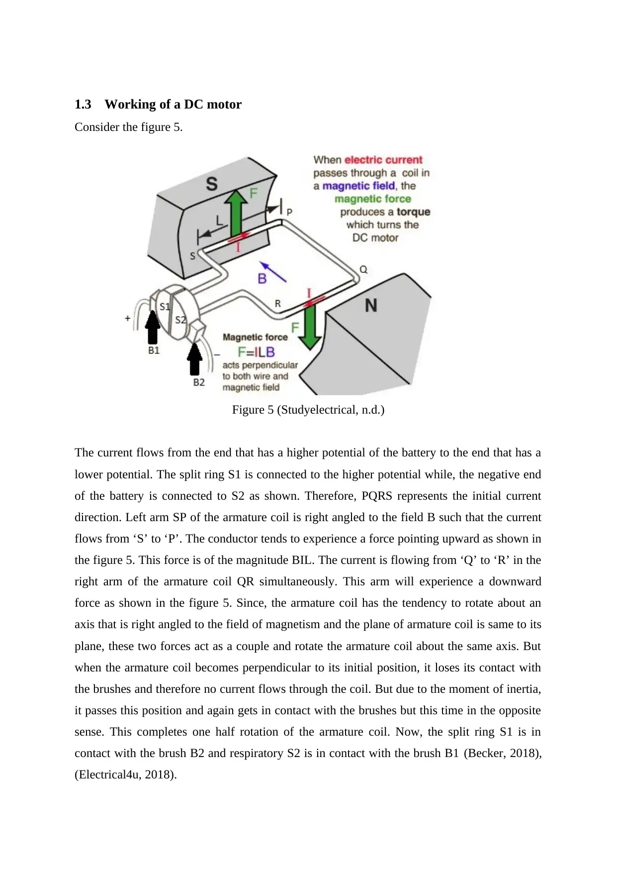
1.3 Working of a DC motor
Consider the figure 5.
Figure 5 (Studyelectrical, n.d.)
The current flows from the end that has a higher potential of the battery to the end that has a
lower potential. The split ring S1 is connected to the higher potential while, the negative end
of the battery is connected to S2 as shown. Therefore, PQRS represents the initial current
direction. Left arm SP of the armature coil is right angled to the field B such that the current
flows from ‘S’ to ‘P’. The conductor tends to experience a force pointing upward as shown in
the figure 5. This force is of the magnitude BIL. The current is flowing from ‘Q’ to ‘R’ in the
right arm of the armature coil QR simultaneously. This arm will experience a downward
force as shown in the figure 5. Since, the armature coil has the tendency to rotate about an
axis that is right angled to the field of magnetism and the plane of armature coil is same to its
plane, these two forces act as a couple and rotate the armature coil about the same axis. But
when the armature coil becomes perpendicular to its initial position, it loses its contact with
the brushes and therefore no current flows through the coil. But due to the moment of inertia,
it passes this position and again gets in contact with the brushes but this time in the opposite
sense. This completes one half rotation of the armature coil. Now, the split ring S1 is in
contact with the brush B2 and respiratory S2 is in contact with the brush B1 (Becker, 2018),
(Electrical4u, 2018).
⊘ This is a preview!⊘
Do you want full access?
Subscribe today to unlock all pages.
Trusted by 1+ million students worldwide
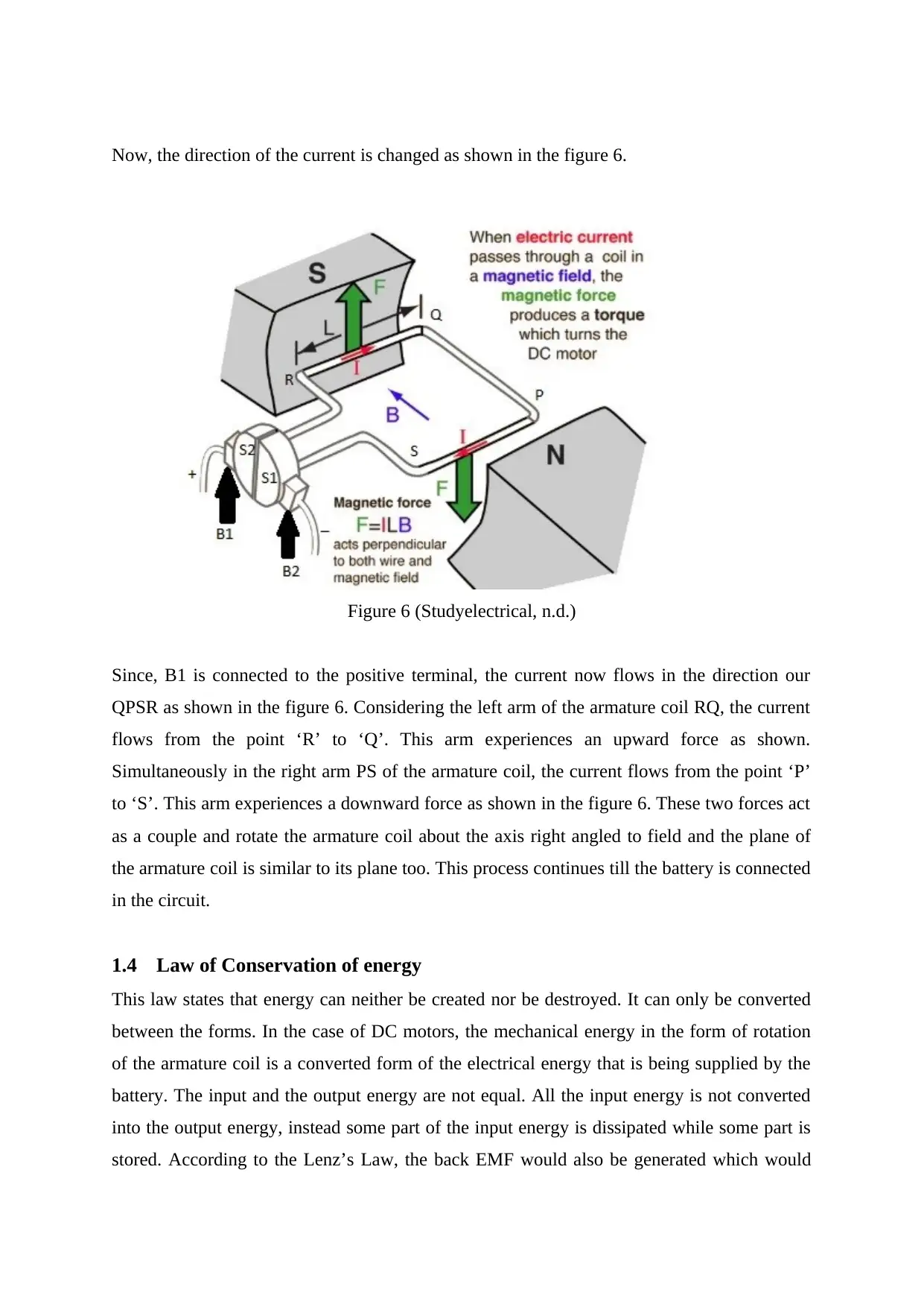
Now, the direction of the current is changed as shown in the figure 6.
Figure 6 (Studyelectrical, n.d.)
Since, B1 is connected to the positive terminal, the current now flows in the direction our
QPSR as shown in the figure 6. Considering the left arm of the armature coil RQ, the current
flows from the point ‘R’ to ‘Q’. This arm experiences an upward force as shown.
Simultaneously in the right arm PS of the armature coil, the current flows from the point ‘P’
to ‘S’. This arm experiences a downward force as shown in the figure 6. These two forces act
as a couple and rotate the armature coil about the axis right angled to field and the plane of
the armature coil is similar to its plane too. This process continues till the battery is connected
in the circuit.
1.4 Law of Conservation of energy
This law states that energy can neither be created nor be destroyed. It can only be converted
between the forms. In the case of DC motors, the mechanical energy in the form of rotation
of the armature coil is a converted form of the electrical energy that is being supplied by the
battery. The input and the output energy are not equal. All the input energy is not converted
into the output energy, instead some part of the input energy is dissipated while some part is
stored. According to the Lenz’s Law, the back EMF would also be generated which would
Paraphrase This Document
Need a fresh take? Get an instant paraphrase of this document with our AI Paraphraser
oppose the armature current so it would act as a loss because its direction is reverse to the
input electrical energy in the form of the armature coil current. The leftover is taken out as
output power. DC motor is an electromechanical device and the energy conversion happens
via electrical and mechanical field. The total electrical energy taken as input is equal to the
sum of electrical energy lost due to losses such as heat, the electrical energy that is stored in
the form of magnetic field because it has greater storage capacity compared to the electrical
field, and the output mechanical energy. The dissipation of the energy also happen in the
form of friction, windage, Eddy current and hysteresis loss (Circuit Globe, n.d.).
1.5 Hazards/ Risks involved with DC motors
There are a number of hazards and risks involved with the DC motors. Some of them are
given below,
1) Electric shock is a common incident that happens with electric motors. The DC
current is more dangerous than AC current therefore it is very dangerous.
2) Burns due to short-circuiting of the DC motors.
3) Injury due to exposure to arcing.
4) Explosion of the faulty parts which becomes worse is the DC motor is installed near
any hazardous or inflammable substances.
5) Lack of maintenance can result in the wearing and tearing of the DC motor surface
that can later result in resting and erosion.
6) Overheating due to lack of proper ventilation and cooling system (Dale, 2015),
(Michelon, 2017).
1.6 Precautions
1) Those places should not be chosen that contain inflammable substances, corrosive and
explosive substances for the installation of the DC motors.
2) Skilful and trained professionals should be appointed and allowed to operate the DC
motors. During the installation itself this should be followed strictly such as during
the wire installation.
3) During any issue occurs in the driver of the DC motor it should be quickly solved
without neglecting because the ignorance of today could lead to a disaster in the
future which can be personal injury or the damage to the apparatus itself.
4) The power supply should be regularly checked and stabilizers should be installed to
check to over-voltage problems that can damage the costly setup.
5) Polarity of the connection should be checked precisely as it may lead to short-circuit.
6) Use the components, drivers of the proper rating compared to the DC motors.
7) Do not bend or twist the wires because as time passes it will become weak at that area
and later become naked.
8) During power cut, switch off the motor too because as soon as the power comes the
motor will start suddenly. This could damage the system.
9) Ensure that the motor is properly cooled during its operation as this could prevent
overheating and later fire.
10) Those motors that are designed to work under intense heat should be marked with any
sticker that warns everyone around it (Eminebea, n.d.), (Ohio Electric Motors
Incorporation, n.d.).
⊘ This is a preview!⊘
Do you want full access?
Subscribe today to unlock all pages.
Trusted by 1+ million students worldwide
1 out of 14
Related Documents


Your All-in-One AI-Powered Toolkit for Academic Success.
+13062052269
info@desklib.com
Available 24*7 on WhatsApp / Email
![[object Object]](/_next/static/media/star-bottom.7253800d.svg)
Unlock your academic potential
Copyright © 2020–2026 A2Z Services. All Rights Reserved. Developed and managed by ZUCOL.