DC Motor Modelling and Control: Analysis and Simulation Project
VerifiedAdded on 2021/12/05
|12
|1120
|217
Project
AI Summary
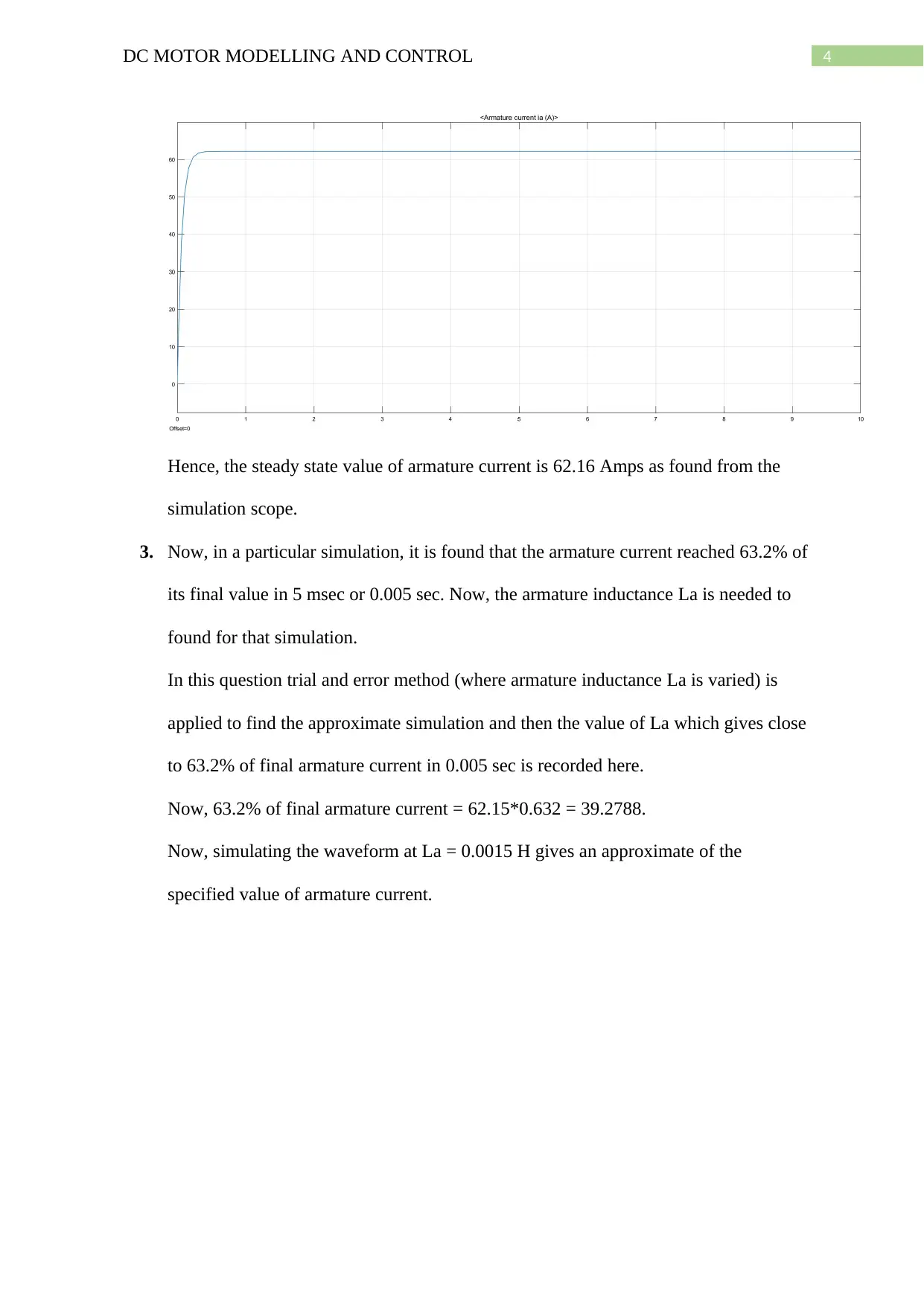
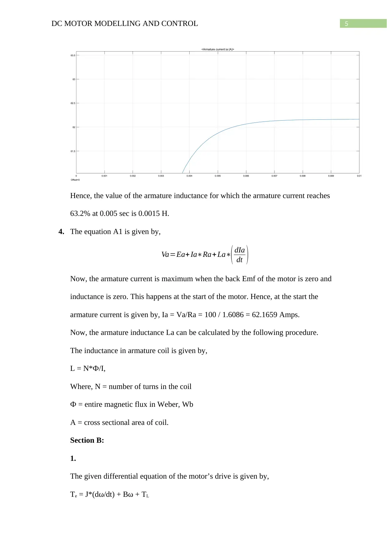
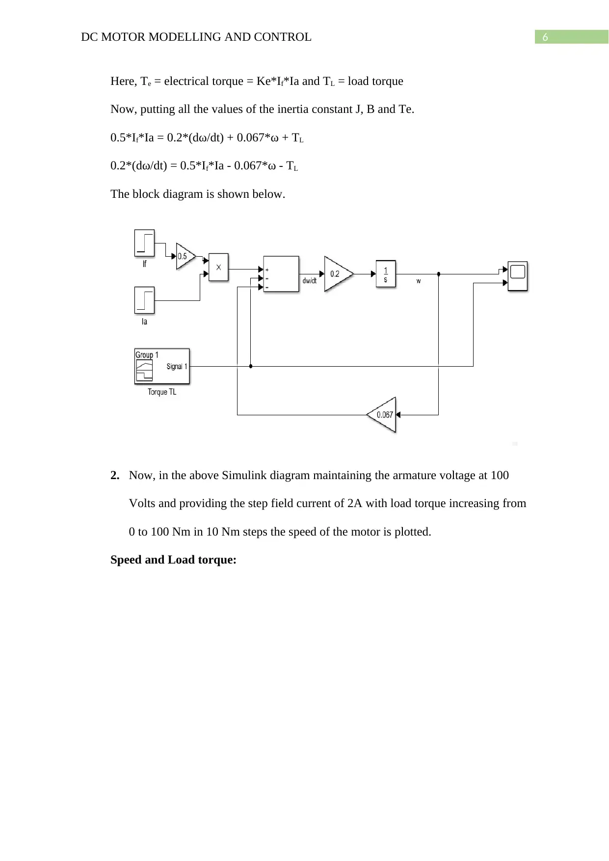
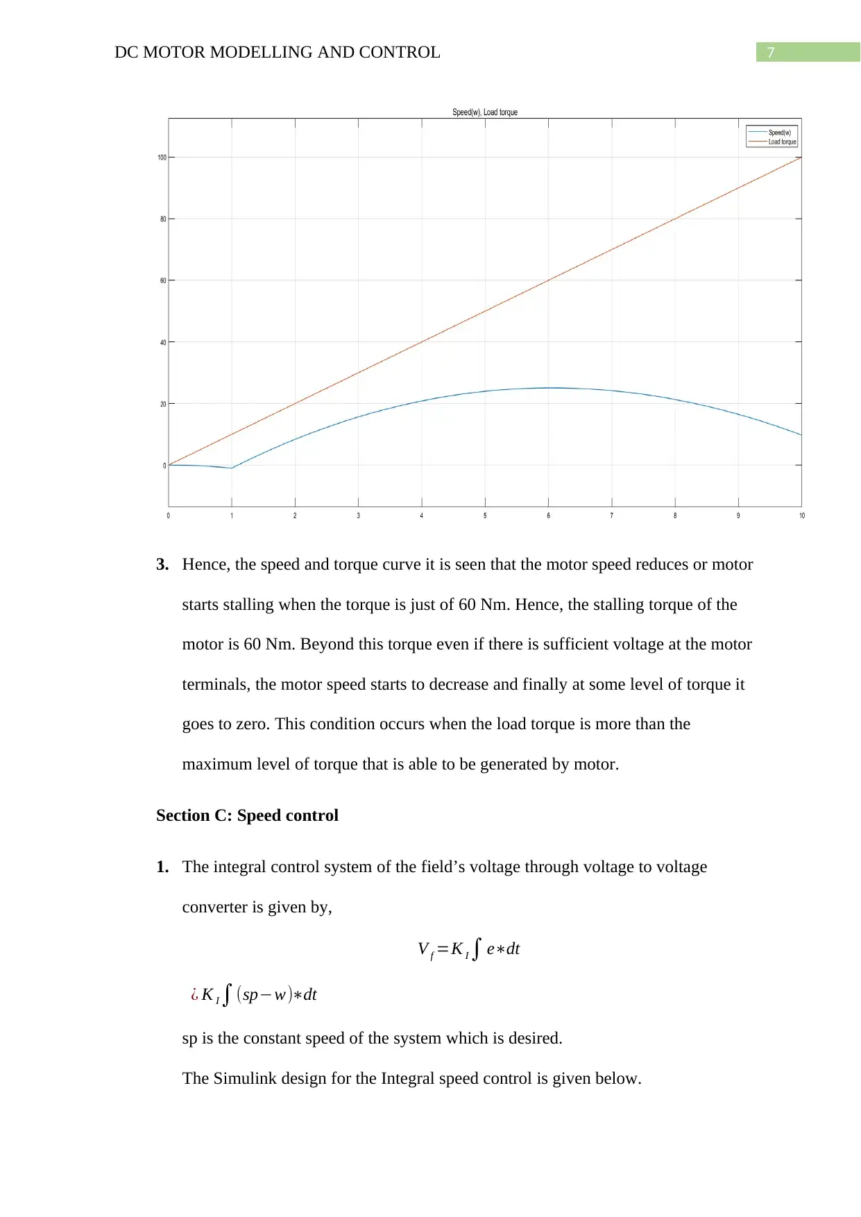
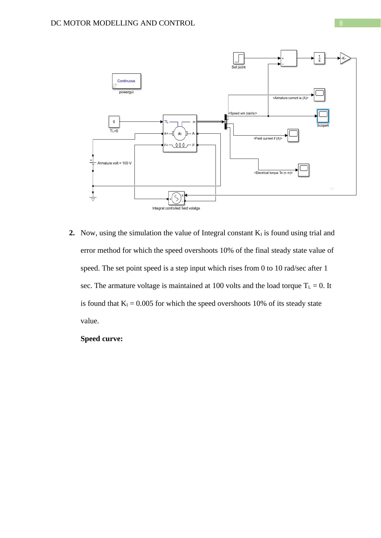
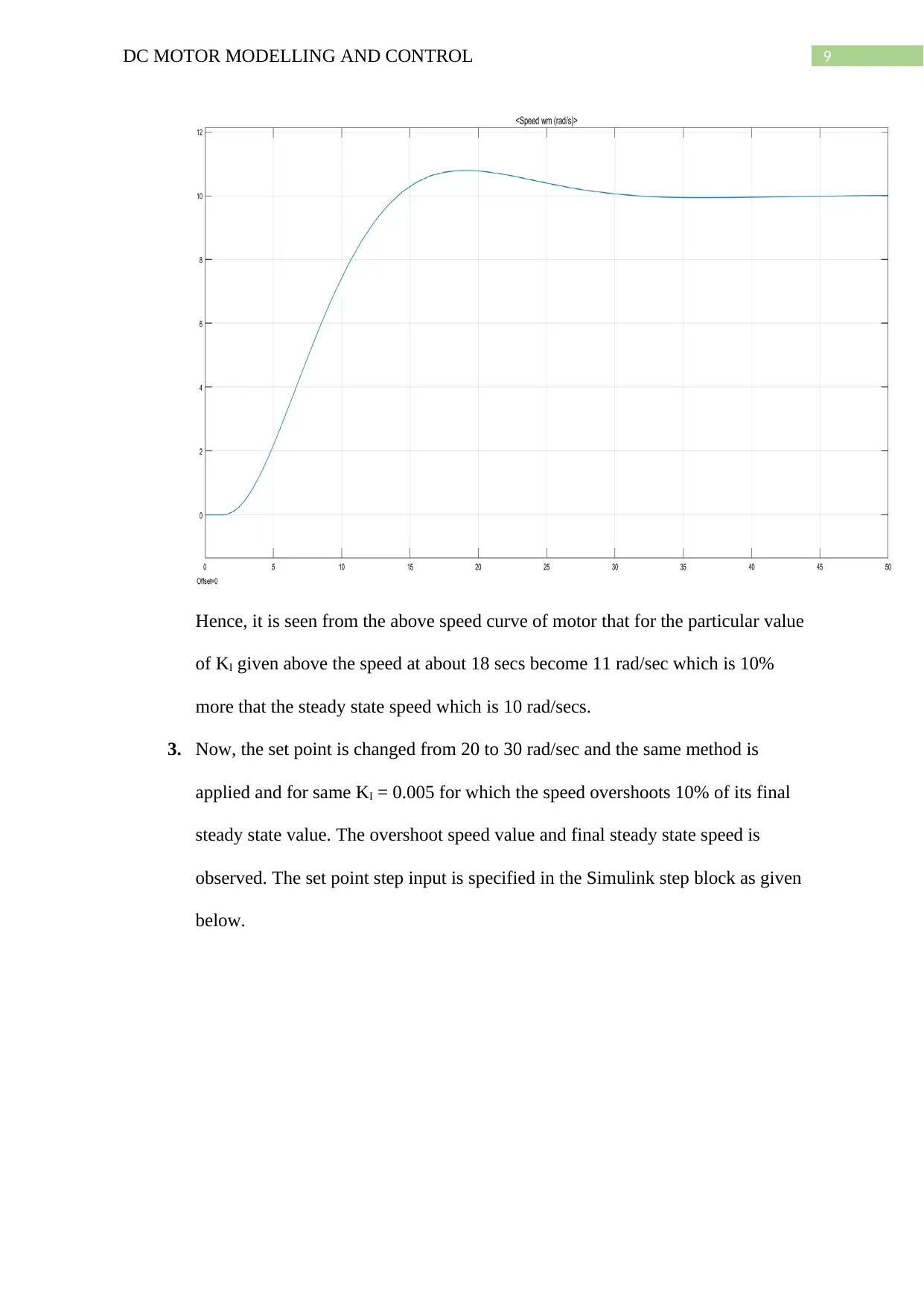
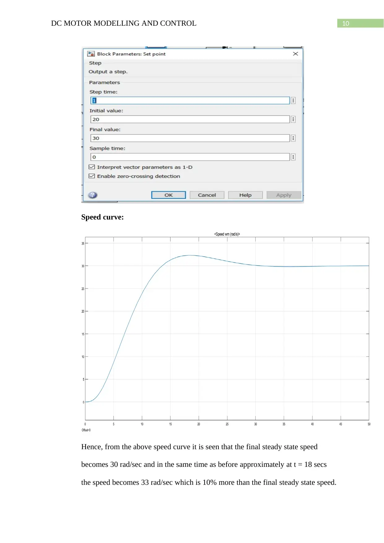
This project focuses on the modeling and control of a separately excited DC motor. It begins with the development of an equivalent circuit diagram and the calculation of key parameters such as armature resistance. The project utilizes Simulink to simulate the motor's behavior, including plots of field and armature currents. The analysis involves determining the armature inductance based on the current's transient response and calculating the maximum armature current. The project further explores the motor's dynamic behavior through differential equations, block diagrams, and simulations to analyze speed and load torque characteristics, including the determination of stalling torque. Finally, the project investigates speed control using an integral control system, with the objective of achieving specific speed set points and analyzing overshoot characteristics by adjusting the integral constant (KI) through trial and error method in Simulink. The project demonstrates the motor's response to different speed set points.

1 out of 12

Your All-in-One AI-Powered Toolkit for Academic Success.
+13062052269
info@desklib.com
Available 24*7 on WhatsApp / Email
![[object Object]](/_next/static/media/star-bottom.7253800d.svg)
Copyright © 2020–2026 A2Z Services. All Rights Reserved. Developed and managed by ZUCOL.