Open/Closed Loop DC Motor Speed Control with Arduino, LabVIEW Analysis
VerifiedAdded on 2023/06/15
|18
|2083
|375
Report
AI Summary
This report investigates the open loop and closed loop speed control of a small DC motor using an Arduino microcontroller and LabVIEW. It details the theory behind open and closed loop control systems, highlighting the advantages and disadvantages of each. The report includes experimental results from a motor rig connected to a 14V DC power supply, with data collected using LabVIEW. Matlab Simulink is used to simulate and verify the system's behavior under ideal conditions, as well as to analyze its response to disturbances and delays. The study also explores PID control and tuning methods, such as the Nichols-Ziegler method, to optimize the closed loop system's performance. The results from both open and closed loop tests are presented and analyzed, including transfer functions and system responses to varying control parameters.

Paraphrase This Document
Need a fresh take? Get an instant paraphrase of this document with our AI Paraphraser

UNIVERSITY NAME
1
2018
department or faculty
student name
student registration number
1
2018
department or faculty
student name
student registration number
ABSTRACT
This report aims at investigating the open loop and closed loop speed control of a small DC
motor. The report defines the closed loop and open loop control systems describing the
drawbacks and merits against each other. The report performs a lab experiment on a motor rig
connected to a 14v DC power supply and tested using LabView to collect data. The Matlab
Simulink is used to verify the ideal conditions of the system while introducing disturbances and
delays to analyze the system response.
2
⊘ This is a preview!⊘
Do you want full access?
Subscribe today to unlock all pages.

Trusted by 1+ million students worldwide
OPEN LOOP AND CLOSED LOOP SPEED CONTROL OF A DC MOTOR USING THE
ARDUINO MICROCONTROLLER AND LABVIEW
INTRODUCTION
A closed loop controller unlike the open loop system, has a feedback loop to observe and
determine if the output of the system is as intended. Consequently, open loop systems are not
used in most practical system in the industry such as machine learning and may not be in a
position to correct errors. In closed loop control first the controlled variable is measured. The
control error is calculated by comparing the control variable with the set point value. The
processing of the control error is done by changing the manipulated variable. Systems where the
output has an effect upon the process input quantity in such a manner as to maintain the desired
output value are known as the closed loop control systems1. One main caveat experienced by the
closed loop systems is the ability to maintain the system stability.
OBJECTIVES
(i) To understand the open loop control systems and how to obtain the transfer functions
of a system by experimentation.
(ii) To comprehend the limitations of open loop control systems through investigation
and reference of the course theory work.
(iii) To review the merits and demerits of closed loop control as well as optimize the
response of the system using PID and to tune the PID controller using Nichols Ziegler
tuning methods.
THEORY
System response using PID control
PID is a controller that contains a linear combination of the proportional (P), integral (I), and
derivative (D). The terms act on a control error or the process output. Statistical information
1 D'azzo, J. J., & Houpis, C. H. (n.d.). Feedback control system Analysis and Synthesis. New York: Mc-Graw Hill.
3
Paraphrase This Document
Need a fresh take? Get an instant paraphrase of this document with our AI Paraphraser
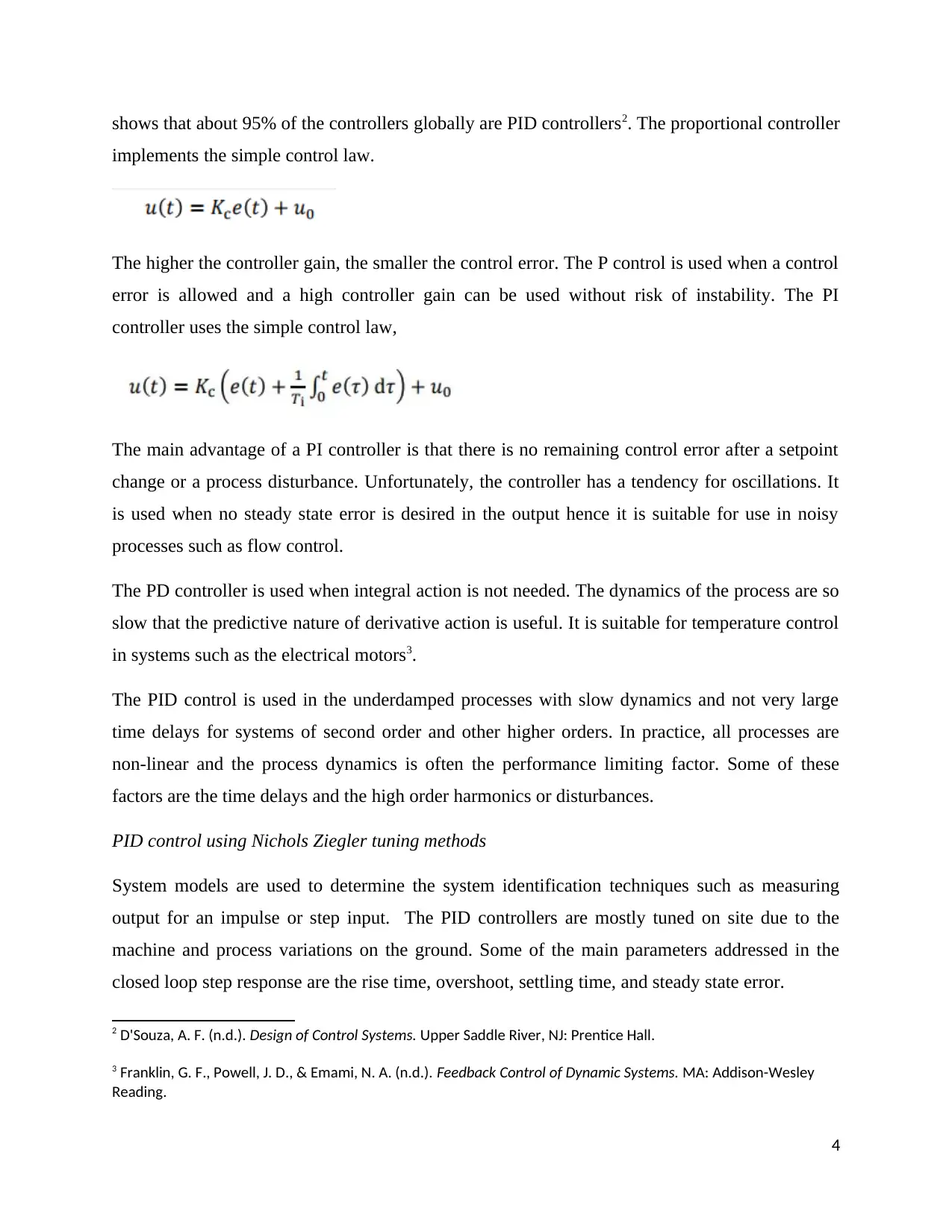
shows that about 95% of the controllers globally are PID controllers2. The proportional controller
implements the simple control law.
The higher the controller gain, the smaller the control error. The P control is used when a control
error is allowed and a high controller gain can be used without risk of instability. The PI
controller uses the simple control law,
The main advantage of a PI controller is that there is no remaining control error after a setpoint
change or a process disturbance. Unfortunately, the controller has a tendency for oscillations. It
is used when no steady state error is desired in the output hence it is suitable for use in noisy
processes such as flow control.
The PD controller is used when integral action is not needed. The dynamics of the process are so
slow that the predictive nature of derivative action is useful. It is suitable for temperature control
in systems such as the electrical motors3.
The PID control is used in the underdamped processes with slow dynamics and not very large
time delays for systems of second order and other higher orders. In practice, all processes are
non-linear and the process dynamics is often the performance limiting factor. Some of these
factors are the time delays and the high order harmonics or disturbances.
PID control using Nichols Ziegler tuning methods
System models are used to determine the system identification techniques such as measuring
output for an impulse or step input. The PID controllers are mostly tuned on site due to the
machine and process variations on the ground. Some of the main parameters addressed in the
closed loop step response are the rise time, overshoot, settling time, and steady state error.
2 D'Souza, A. F. (n.d.). Design of Control Systems. Upper Saddle River, NJ: Prentice Hall.
3 Franklin, G. F., Powell, J. D., & Emami, N. A. (n.d.). Feedback Control of Dynamic Systems. MA: Addison-Wesley
Reading.
4
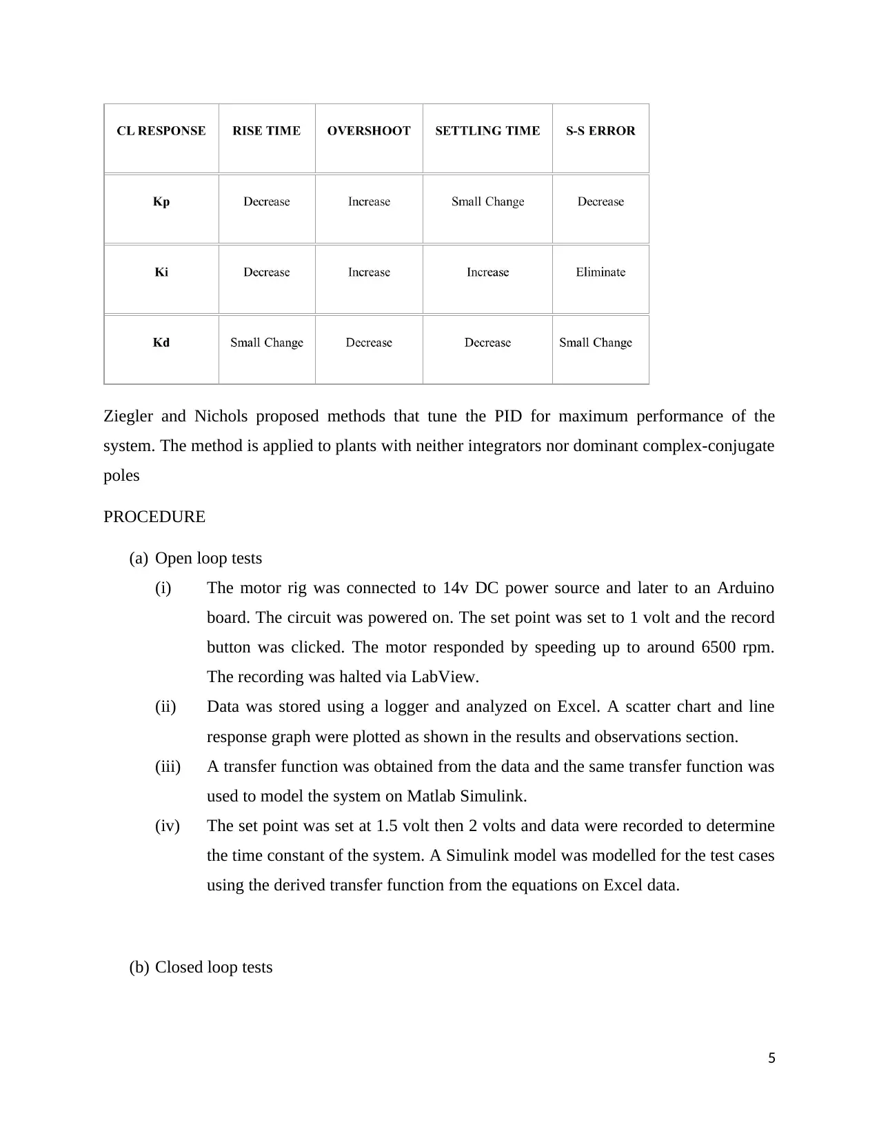
Ziegler and Nichols proposed methods that tune the PID for maximum performance of the
system. The method is applied to plants with neither integrators nor dominant complex-conjugate
poles
PROCEDURE
(a) Open loop tests
(i) The motor rig was connected to 14v DC power source and later to an Arduino
board. The circuit was powered on. The set point was set to 1 volt and the record
button was clicked. The motor responded by speeding up to around 6500 rpm.
The recording was halted via LabView.
(ii) Data was stored using a logger and analyzed on Excel. A scatter chart and line
response graph were plotted as shown in the results and observations section.
(iii) A transfer function was obtained from the data and the same transfer function was
used to model the system on Matlab Simulink.
(iv) The set point was set at 1.5 volt then 2 volts and data were recorded to determine
the time constant of the system. A Simulink model was modelled for the test cases
using the derived transfer function from the equations on Excel data.
(b) Closed loop tests
5
⊘ This is a preview!⊘
Do you want full access?
Subscribe today to unlock all pages.

Trusted by 1+ million students worldwide
(i) The closed_loop.bin file was copied to the microcontroller and the reset button
was pressed. The closed loop LabView program was started and the set point was
adjusted to test the working of the system.
(ii) The set point was recorded as 10000 rpm. The tuning was done by altering
different parameters of the PID controller to obtain the results in the section
below.
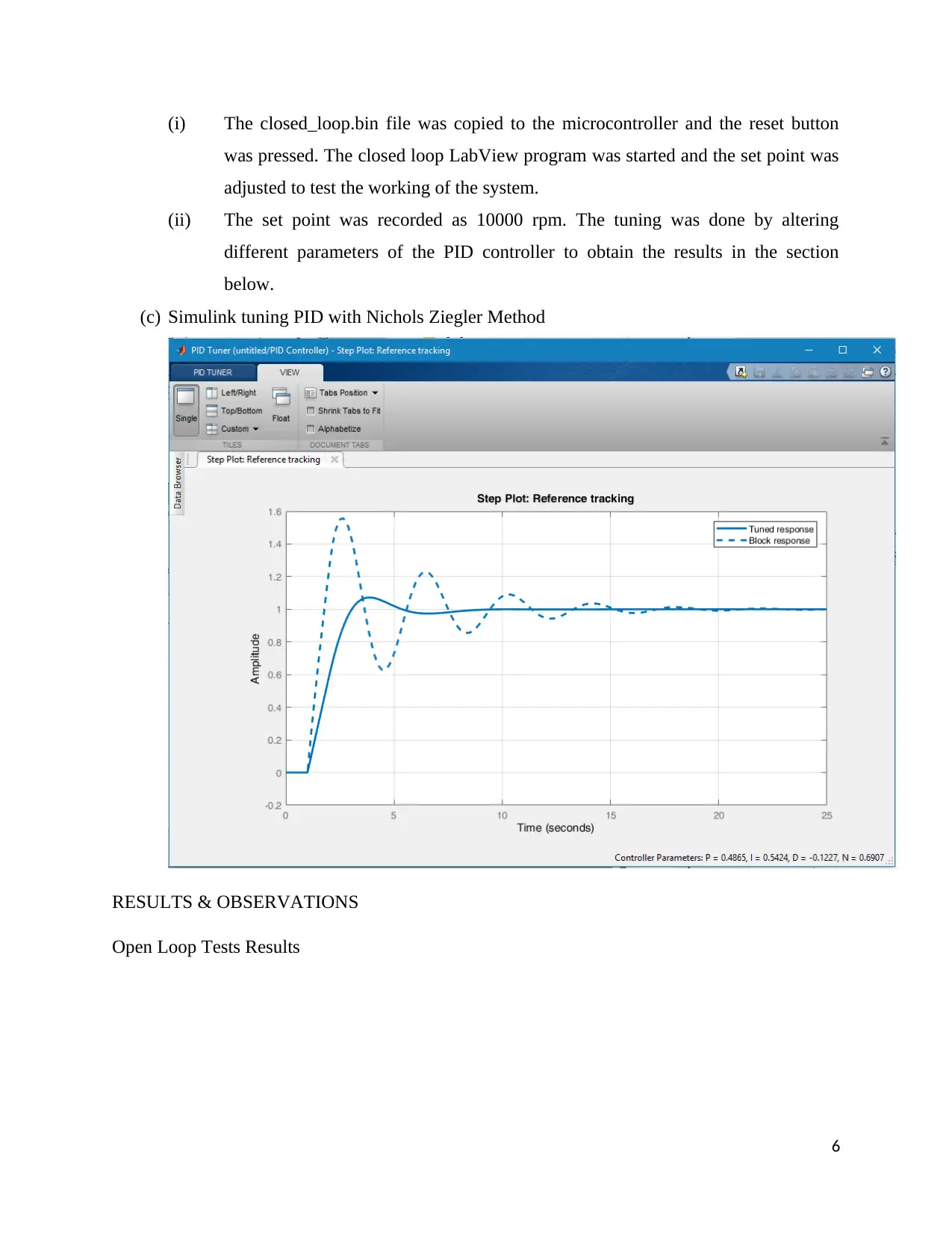
(c) Simulink tuning PID with Nichols Ziegler Method
RESULTS & OBSERVATIONS
Open Loop Tests Results
6
Paraphrase This Document
Need a fresh take? Get an instant paraphrase of this document with our AI Paraphraser
0 1 2 3 4 5 6
0
1000
2000
3000
4000
5000
6000
7000
RPM AGAINST TIME SIMULATIONS
SIMULATIONS
DC MOTOR SPEED (rpm)
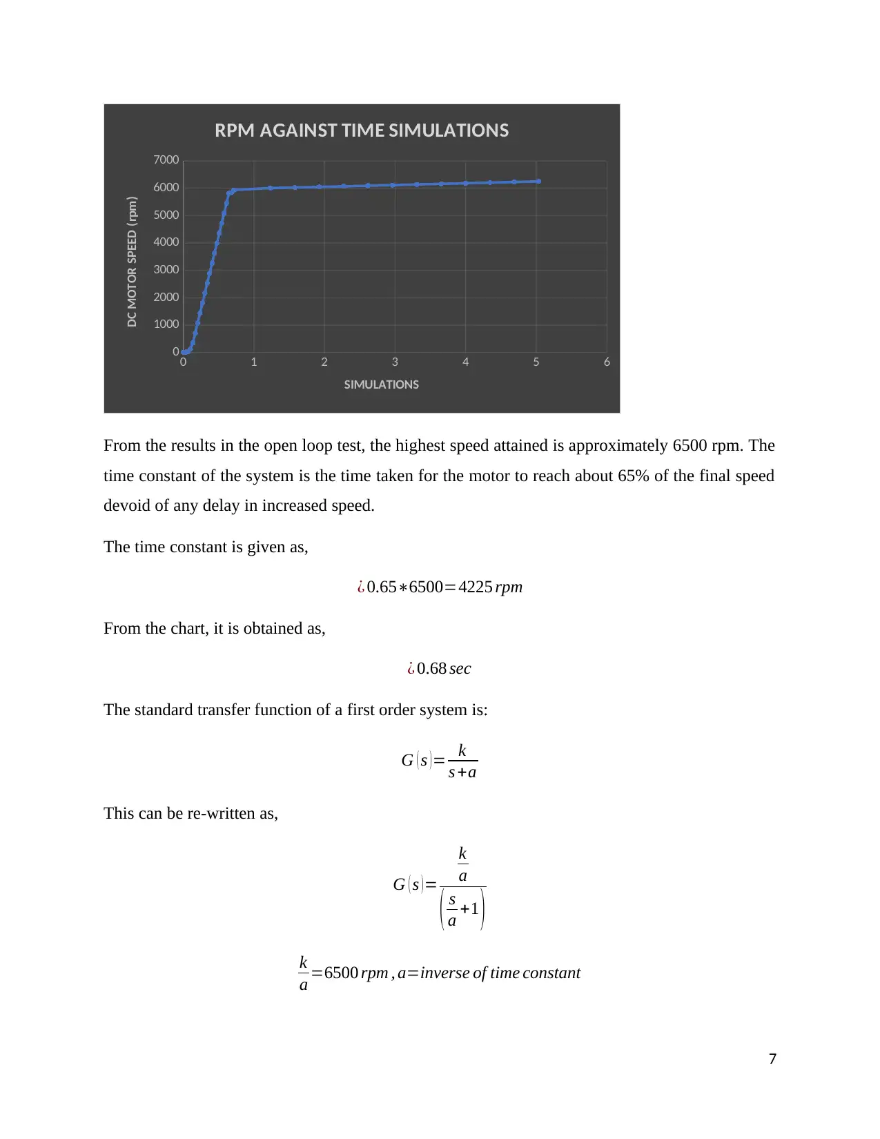
From the results in the open loop test, the highest speed attained is approximately 6500 rpm. The
time constant of the system is the time taken for the motor to reach about 65% of the final speed
devoid of any delay in increased speed.
The time constant is given as,
¿ 0.65∗6500=4225 rpm
From the chart, it is obtained as,
¿ 0.68 sec
The standard transfer function of a first order system is:
G ( s ) = k
s +a
This can be re-written as,
G ( s ) =
k
a
( s
a +1 )
k
a =6500 rpm , a=inverse of time constant
7
τ ( inv )= 1
0.68 =1.47 sec−1
G ( s )= 9558
s +1.47
G ( s )= 1.47
s +1.47 ∈terms of rpm
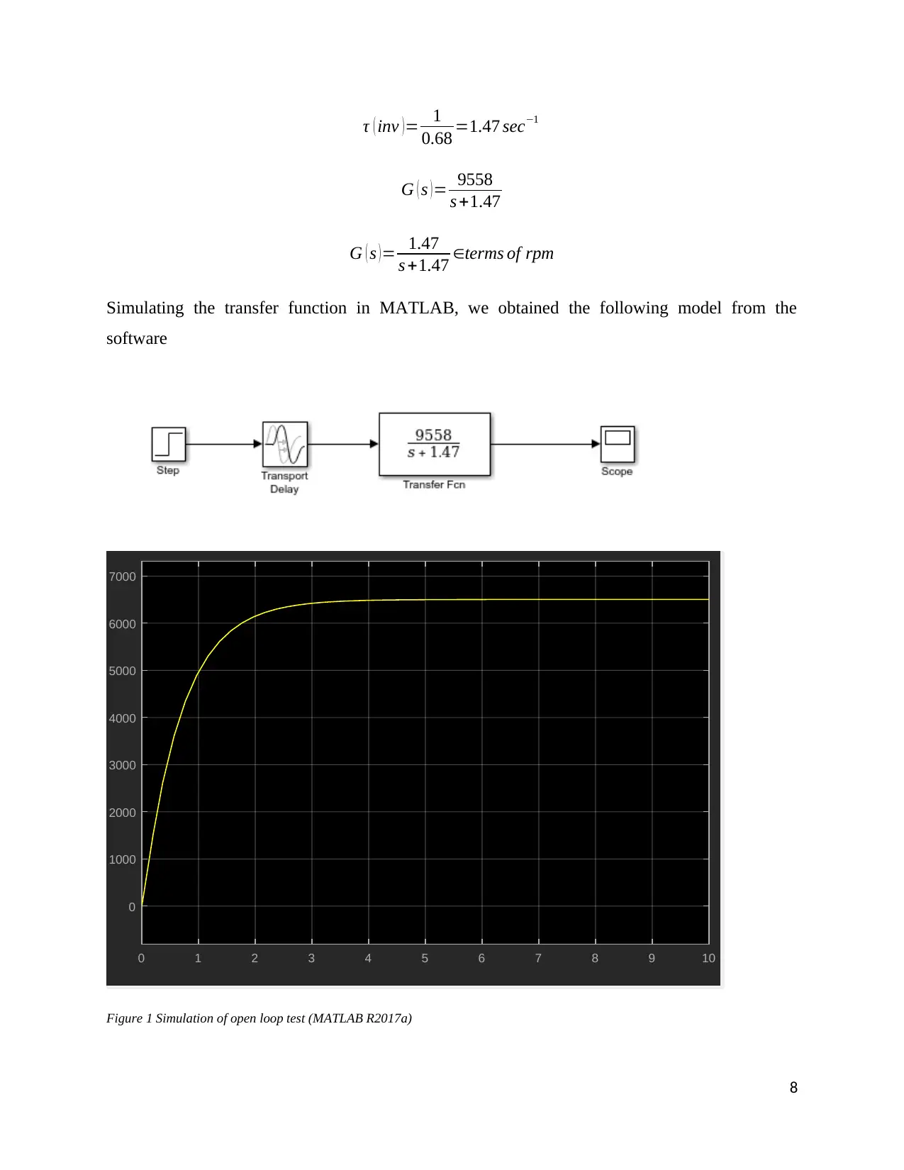
Simulating the transfer function in MATLAB, we obtained the following model from the
software
0 1 2 3 4 5 6 7 8 9 10
0
1000
2000
3000
4000
5000
6000
7000
Figure 1 Simulation of open loop test (MATLAB R2017a)
8
0.68 =1.47 sec−1
G ( s )= 9558
s +1.47
G ( s )= 1.47
s +1.47 ∈terms of rpm
Simulating the transfer function in MATLAB, we obtained the following model from the
software
0 1 2 3 4 5 6 7 8 9 10
0
1000
2000
3000
4000
5000
6000
7000
Figure 1 Simulation of open loop test (MATLAB R2017a)
8
⊘ This is a preview!⊘
Do you want full access?
Subscribe today to unlock all pages.

Trusted by 1+ million students worldwide
From the graph developed from the Excel data and the transfer function, there is a close
similarity that demonstrates the smooth DC motor speed as time progresses. The maximum
speed goes to 6500 rpm as initially intended.
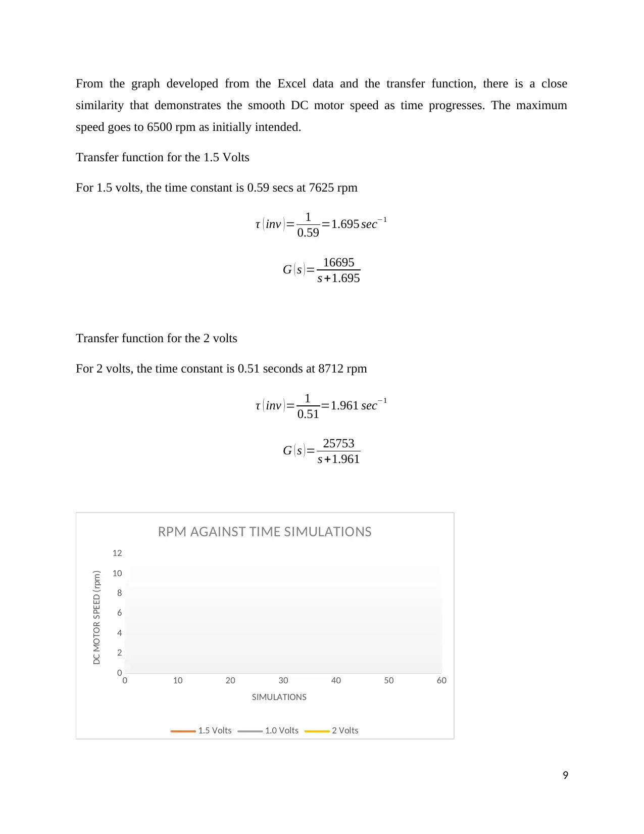
Transfer function for the 1.5 Volts
For 1.5 volts, the time constant is 0.59 secs at 7625 rpm
τ ( inv )= 1
0.59 =1.695 sec−1
G ( s ) = 16695
s +1.695
Transfer function for the 2 volts
For 2 volts, the time constant is 0.51 seconds at 8712 rpm
τ ( inv )= 1
0.51=1.961 sec−1
G ( s )= 25753
s +1.961
0 10 20 30 40 50 60
0
2
4
6
8
10
12
RPM AGAINST TIME SIMULATIONS
1.5 Volts 1.0 Volts 2 Volts
SIMULATIONS
DC MOTOR SPEED (rpm)
9
Paraphrase This Document
Need a fresh take? Get an instant paraphrase of this document with our AI Paraphraser
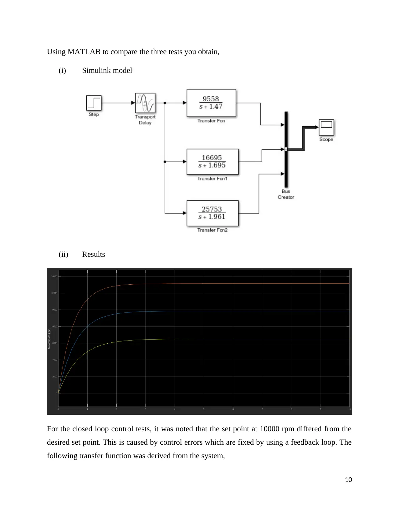
Using MATLAB to compare the three tests you obtain,
(i) Simulink model
(ii) Results
For the closed loop control tests, it was noted that the set point at 10000 rpm differed from the
desired set point. This is caused by control errors which are fixed by using a feedback loop. The
following transfer function was derived from the system,
10
(i) Simulink model
(ii) Results
For the closed loop control tests, it was noted that the set point at 10000 rpm differed from the
desired set point. This is caused by control errors which are fixed by using a feedback loop. The
following transfer function was derived from the system,
10
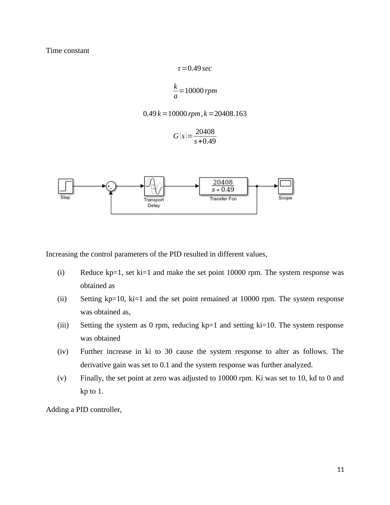
Time constant
τ =0.49 sec
k
a =10000 rpm
0.49 k =10000 rpm, k =20408.163
G ( s ) = 20408
s +0.49
Increasing the control parameters of the PID resulted in different values,
(i) Reduce kp=1, set ki=1 and make the set point 10000 rpm. The system response was
obtained as
(ii) Setting kp=10, ki=1 and the set point remained at 10000 rpm. The system response
was obtained as,
(iii) Setting the system as 0 rpm, reducing kp=1 and setting ki=10. The system response
was obtained
(iv) Further increase in ki to 30 cause the system response to alter as follows. The
derivative gain was set to 0.1 and the system response was further analyzed.
(v) Finally, the set point at zero was adjusted to 10000 rpm. Ki was set to 10, kd to 0 and
kp to 1.
Adding a PID controller,
11
⊘ This is a preview!⊘
Do you want full access?
Subscribe today to unlock all pages.

Trusted by 1+ million students worldwide
1 out of 18
Related Documents
Your All-in-One AI-Powered Toolkit for Academic Success.
+13062052269
info@desklib.com
Available 24*7 on WhatsApp / Email
![[object Object]](/_next/static/media/star-bottom.7253800d.svg)
Unlock your academic potential
Copyright © 2020–2026 A2Z Services. All Rights Reserved. Developed and managed by ZUCOL.


