logo

DC Motor Speed Control using PI Control Assignment 2022

The aim of this lab session is to understand DC motor speed control using PI control in LabView. The lab report will contribute to 20% of the final mark of the module.

12 Pages2505 Words13 Views
   

Added on  2022-08-26

DC Motor Speed Control using PI Control Assignment 2022

The aim of this lab session is to understand DC motor speed control using PI control in LabView. The lab report will contribute to 20% of the final mark of the module.

   Added on 2022-08-26

ShareRelated Documents
DC Motor Speed Control using PI Control
Student Name
ID number
Attended Lab Session Date / Time
DC Motor Speed Control using PI Control Assignment 2022_1
Introduction
The device operation relies on straightforward electromagnetism in any electrical device. A
current-conveying conductor creates a field which is attractive in nature. When a current-
carrying conductor is put in an attractive field outside, a power corresponding to the current
in the conductor and the outer attractive field strength will be experienced. In a magnet, the
opposite polarities ( N and S ) pull in, while they repulse like polarities ( N and West, East
and S ). The internal arrangement of a DC engine is designed to saddle the attractive
collaboration between a current-conveying conductor and an attractive field outside to create
rotational motion.
That DC engine consists of 6 essential parts including hub, rotor called as armature, stator,
switch, field magnet and brushes. The outer attractive field is delivered using perpetual
magnets of good quality in most normal DC engines. The stator is the engine's stationary
component-this includes the engine packaging, at least 2 enduring bits of magnet shaft. The
rotor in relation to the stator, together with the pivot and the appended commutator turn. For
most of the cases, the rotor consists of windings on a center, the windings being connected
electrically to the commutator. The Figure 1 shows a typical engine design inside the stator or
field magnets, with the rotor.
The brushes ' geometry, commutator contacts, and rotor windings are designed such that the p
olarity of the stimulated winding and the stator magnet is bent when force is applied, and the
rotor can rotate until it is almost aligned with the field magnets of the stator. The brushes shift
to the following switching contacts as the rotor arrives at arrangement and allows the
following winding. Because of our two shaft engine configurations, the spinning action due
to revolution around the current bearing through the spinning action of the rotor which causes
a flip in the enticing area of the rotor, which forces it to stay pivotal.
Nonetheless, taking all the factors under consideration, the DC engines are going to regularly
have many posts (3 is a common count). Actually, the commutator stays away from dead
ends. A two-post model engine gets stuck in case the rotor is actually at the centre of the turn
splendidly aligned along with the field magnets. In the meantime, using a two-
shaft motor, the switch leads to the
shorting of the supply of power, i.e. the two brushes simultaneously touch all switching conta
cts. This would be bad for the supply of power, squandering energy and also hurting parts of t
DC Motor Speed Control using PI Control Assignment 2022_2
he engine.
Another drawback of such a simple engine is that it will present a high torque ripple measure.
The torque it produces is cyclic in nature.
The most widely used actuators are the Brushed DC motors.They are available in different siz
es and can be optimized for output angular velocity or torque generation for various purposes.
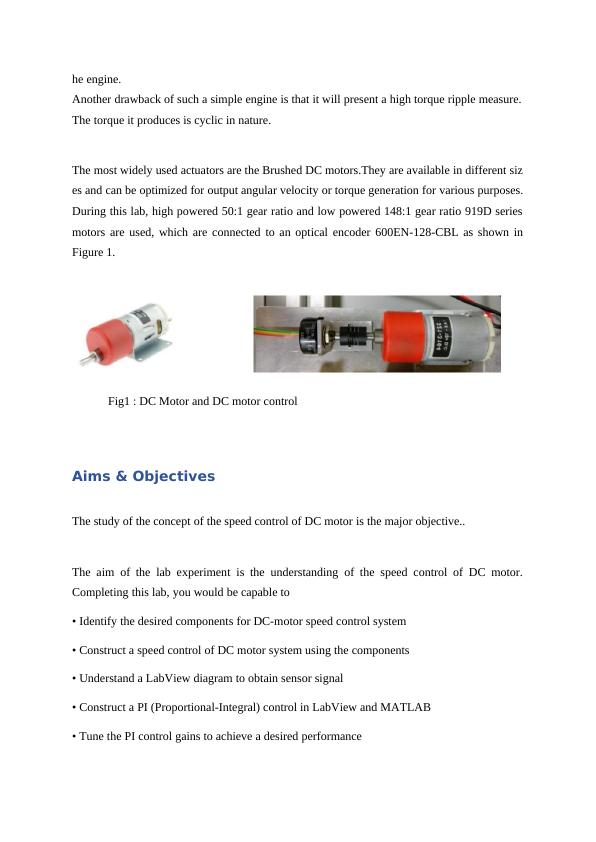
During this lab, high powered 50:1 gear ratio and low powered 148:1 gear ratio 919D series
motors are used, which are connected to an optical encoder 600EN-128-CBL as shown in
Figure 1.
Fig1 : DC Motor and DC motor control
Aims & Objectives
The study of the concept of the speed control of DC motor is the major objective..
The aim of the lab experiment is the understanding of the speed control of DC motor.
Completing this lab, you would be capable to
• Identify the desired components for DC-motor speed control system
• Construct a speed control of DC motor system using the components
• Understand a LabView diagram to obtain sensor signal
• Construct a PI (Proportional-Integral) control in LabView and MATLAB
• Tune the PI control gains to achieve a desired performance
DC Motor Speed Control using PI Control Assignment 2022_3
• Identify a transfer function between input and output signals
Methods :
Task 1 :
Hardware and Software Components :
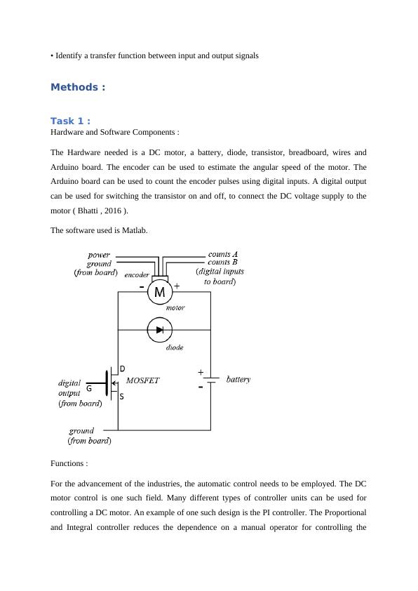
The Hardware needed is a DC motor, a battery, diode, transistor, breadboard, wires and
Arduino board. The encoder can be used to estimate the angular speed of the motor. The
Arduino board can be used to count the encoder pulses using digital inputs. A digital output
can be used for switching the transistor on and off, to connect the DC voltage supply to the
motor ( Bhatti , 2016 ).
The software used is Matlab.
Functions :
For the advancement of the industries, the automatic control needs to be employed. The DC
motor control is one such field. Many different types of controller units can be used for
controlling a DC motor. An example of one such design is the PI controller. The Proportional
and Integral controller reduces the dependence on a manual operator for controlling the
DC Motor Speed Control using PI Control Assignment 2022_4

End of preview

Want to access all the pages? Upload your documents or become a member.

Related Documents
Comparison between Brushless DC Motors and Brushed DC Motors
|5
|1185
|463

Classifications of DC Motors
|15
|1933
|121

ELEC431 Software Engineering and Programming Assignment
|14
|1176
|234

DC Motor Depth Study-Report
|10
|2241
|446

Brushless DC Motor: Construction, Working Principle, and Parts
|8
|1266
|63

DC and AC Motor Construction and Working Principle
|11
|1409
|332