Electrical and Electronic Principles: DC Networks Assignment Analysis
VerifiedAdded on 2023/01/23
|8
|501
|100
Homework Assignment
AI Summary
This document presents a comprehensive solution to a DC Networks assignment, likely for an Electrical Engineering course. The solution begins with the analysis of two DC circuits (Circuit A and Circuit B), calculating total resistance, current, and voltage drops across various components using Ohm...
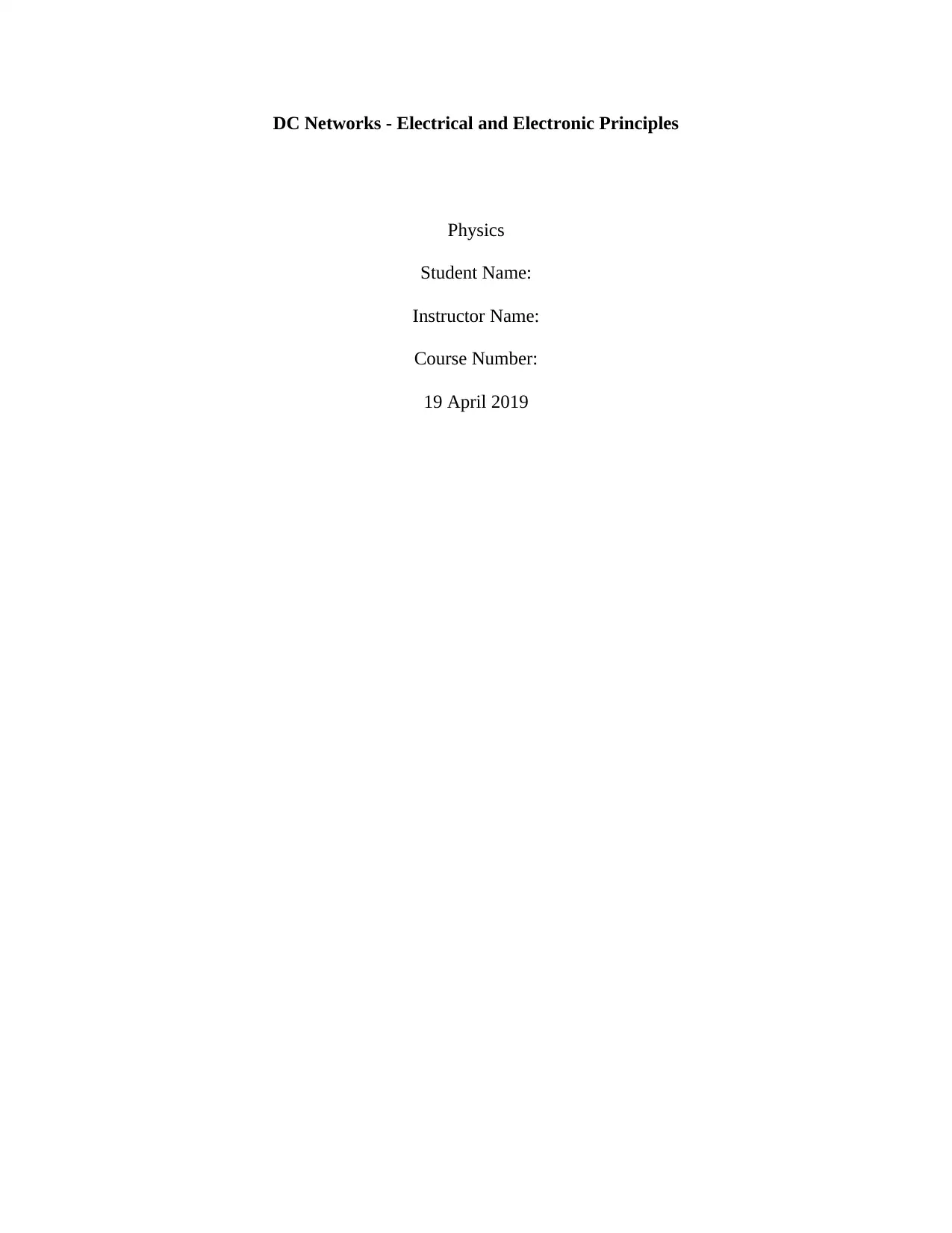
DC Networks - Electrical and Electronic Principles
Physics
Student Name:
Instructor Name:
Course Number:
19 April 2019
Physics
Student Name:
Instructor Name:
Course Number:
19 April 2019
Paraphrase This Document
Need a fresh take? Get an instant paraphrase of this document with our AI Paraphraser
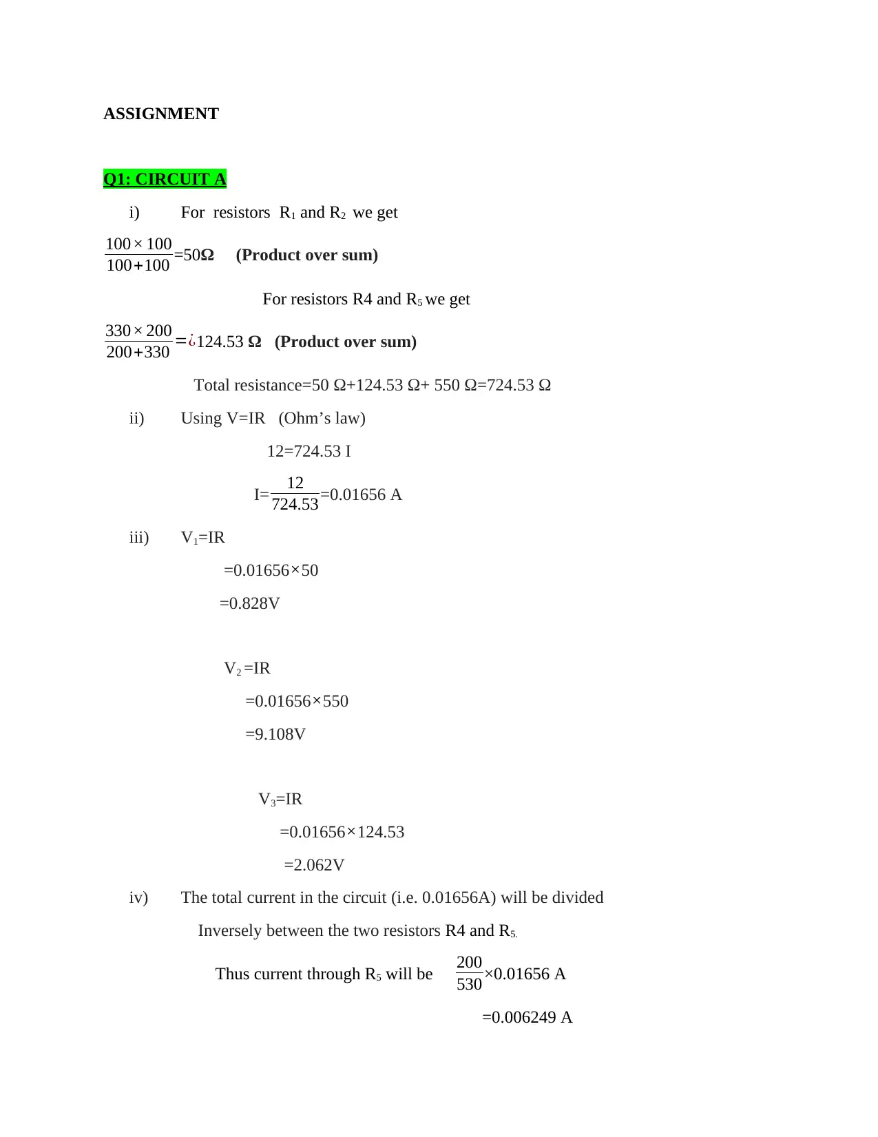
ASSIGNMENT
Q1: CIRCUIT A
i) For resistors R1 and R2 we get
100× 100
100+100 =50Ω (Product over sum)
For resistors R4 and R5 we get
330× 200
200+330 =¿124.53 Ω (Product over sum)
Total resistance=50 Ω+124.53 Ω+ 550 Ω=724.53 Ω
ii) Using V=IR (Ohm’s law)
12=724.53 I
I= 12
724.53=0.01656 A
iii) V1=IR
=0.01656×50
=0.828V
V2 =IR
=0.01656×550
=9.108V
V3=IR
=0.01656×124.53
=2.062V
iv) The total current in the circuit (i.e. 0.01656A) will be divided
Inversely between the two resistors R4 and R5.
Thus current through R5 will be 200
530 ×0.01656 A
=0.006249 A
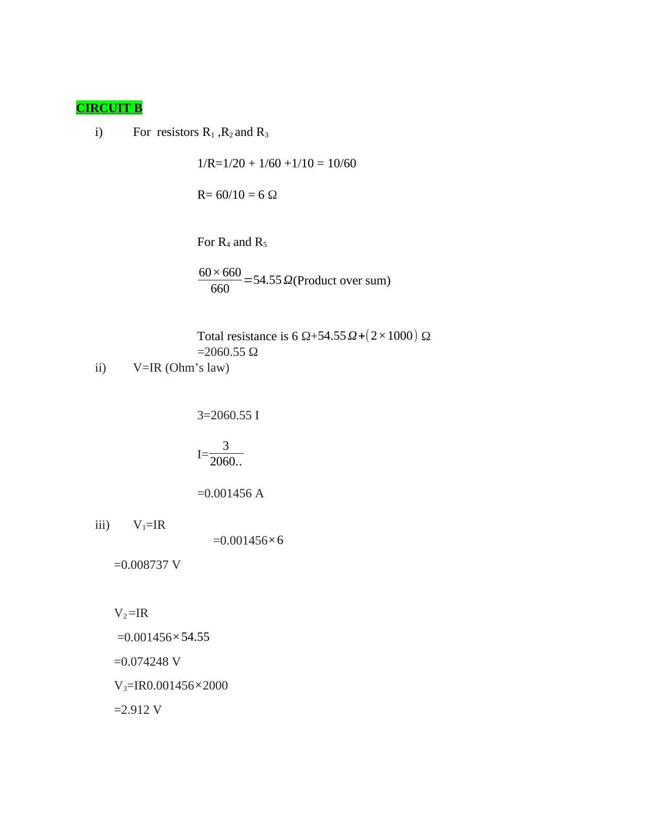
CIRCUIT B
i) For resistors R1 ,R2 and R3
1/R=1/20 + 1/60 +1/10 = 10/60
R= 60/10 = 6 Ω
For R4 and R5
60× 660
660 =54.55 Ω(Product over sum)
Total resistance is 6 Ω+54.55 Ω+( 2×1000) Ω
=2060.55 Ω
ii) V=IR (Ohm’s law)
3=2060.55 I
I= 3
2060..
=0.001456 A
iii) V1=IR
=0.001456×6
=0.008737 V
V2 =IR
=0.001456×54.55
=0.074248 V
V3=IR0.001456×2000
=2.912 V
⊘ This is a preview!⊘
Do you want full access?
Subscribe today to unlock all pages.

Trusted by 1+ million students worldwide
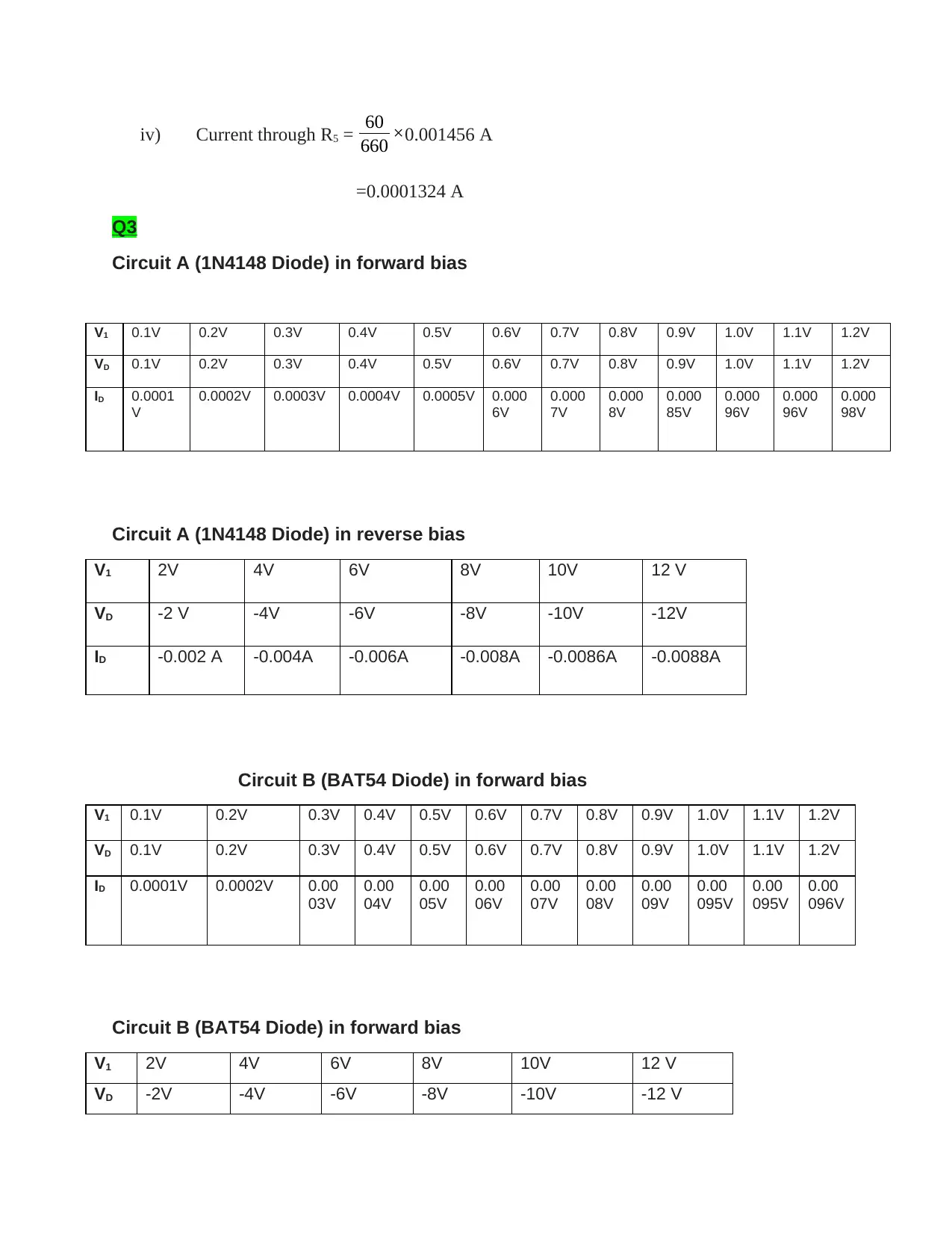
iv) Current through R5 = 60
660 ×0.001456 A
=0.0001324 A
Q3
Circuit A (1N4148 Diode) in forward bias
V1 0.1V 0.2V 0.3V 0.4V 0.5V 0.6V 0.7V 0.8V 0.9V 1.0V 1.1V 1.2V
VD 0.1V 0.2V 0.3V 0.4V 0.5V 0.6V 0.7V 0.8V 0.9V 1.0V 1.1V 1.2V
ID 0.0001
V
0.0002V 0.0003V 0.0004V 0.0005V 0.000
6V
0.000
7V
0.000
8V
0.000
85V
0.000
96V
0.000
96V
0.000
98V
Circuit A (1N4148 Diode) in reverse bias
V1 2V 4V 6V 8V 10V 12 V
VD -2 V -4V -6V -8V -10V -12V
ID -0.002 A -0.004A -0.006A -0.008A -0.0086A -0.0088A
Circuit B (BAT54 Diode) in forward bias
V1 0.1V 0.2V 0.3V 0.4V 0.5V 0.6V 0.7V 0.8V 0.9V 1.0V 1.1V 1.2V
VD 0.1V 0.2V 0.3V 0.4V 0.5V 0.6V 0.7V 0.8V 0.9V 1.0V 1.1V 1.2V
ID 0.0001V 0.0002V 0.00
03V
0.00
04V
0.00
05V
0.00
06V
0.00
07V
0.00
08V
0.00
09V
0.00
095V
0.00
095V
0.00
096V
Circuit B (BAT54 Diode) in forward bias
V1 2V 4V 6V 8V 10V 12 V
VD -2V -4V -6V -8V -10V -12 V
Paraphrase This Document
Need a fresh take? Get an instant paraphrase of this document with our AI Paraphraser
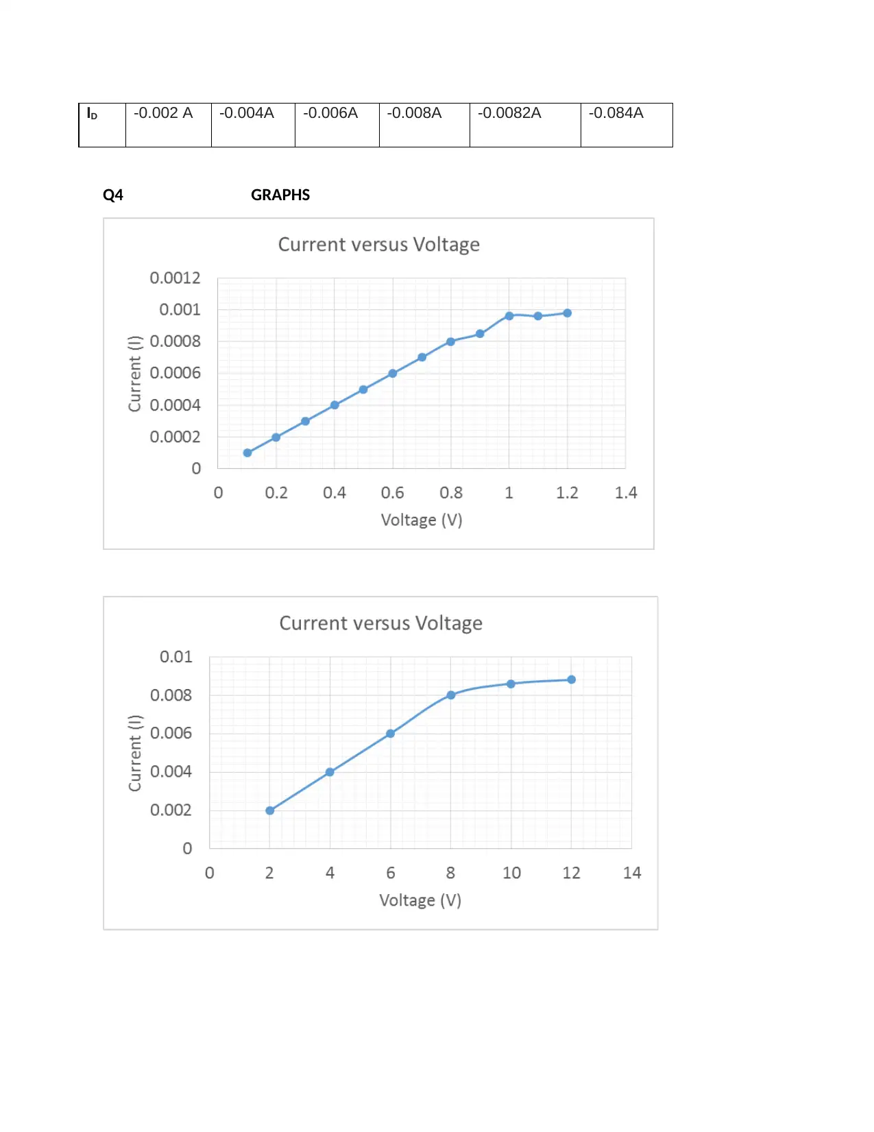
ID -0.002 A -0.004A -0.006A -0.008A -0.0082A -0.084A
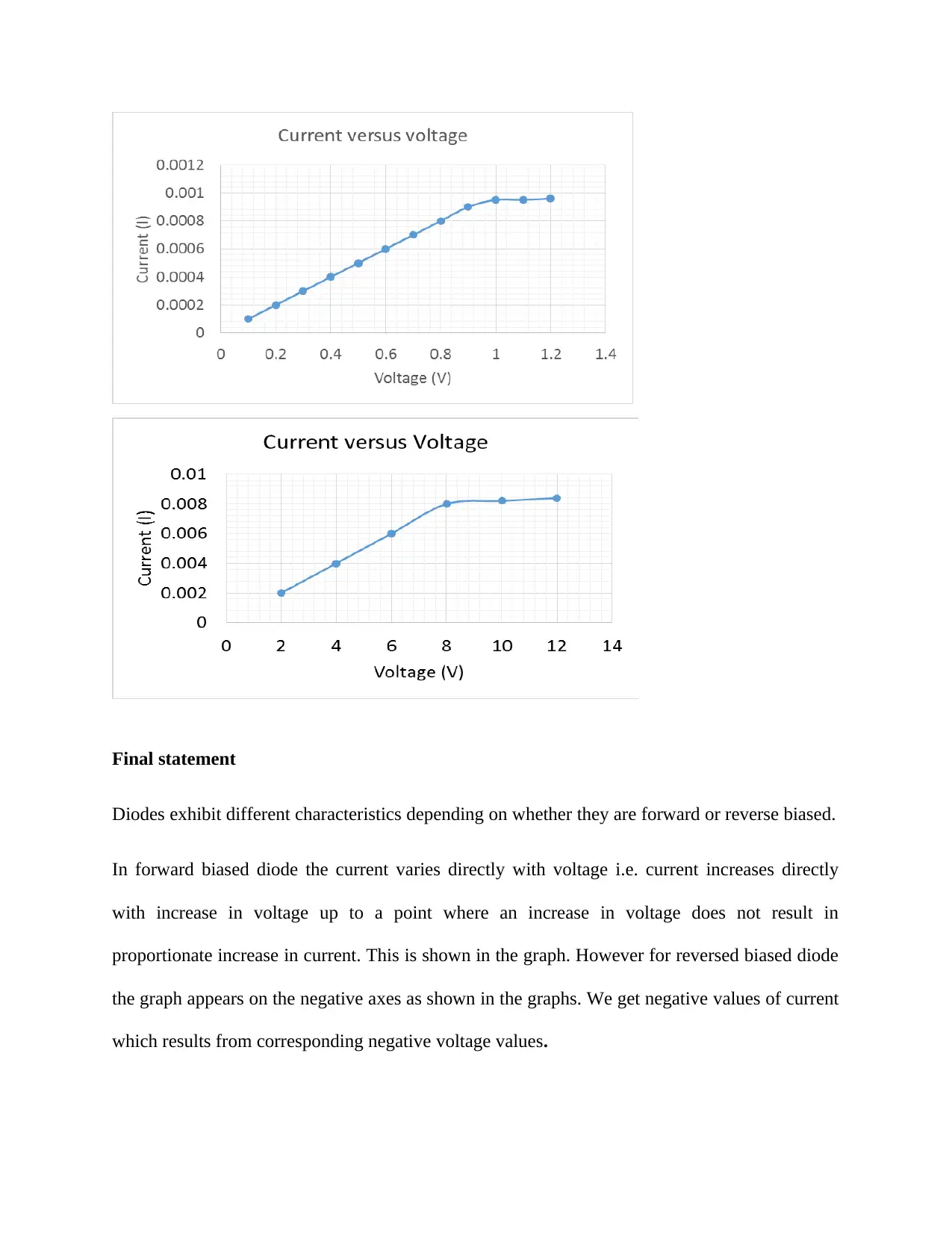
Q4 GRAPHS
Q4 GRAPHS
Final statement
Diodes exhibit different characteristics depending on whether they are forward or reverse biased.
In forward biased diode the current varies directly with voltage i.e. current increases directly
with increase in voltage up to a point where an increase in voltage does not result in
proportionate increase in current. This is shown in the graph. However for reversed biased diode
the graph appears on the negative axes as shown in the graphs. We get negative values of current
which results from corresponding negative voltage values.
⊘ This is a preview!⊘
Do you want full access?
Subscribe today to unlock all pages.

Trusted by 1+ million students worldwide
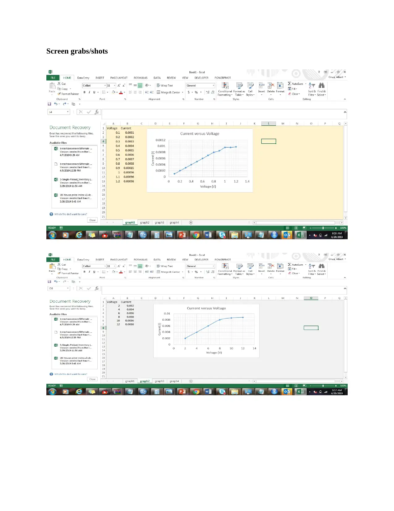
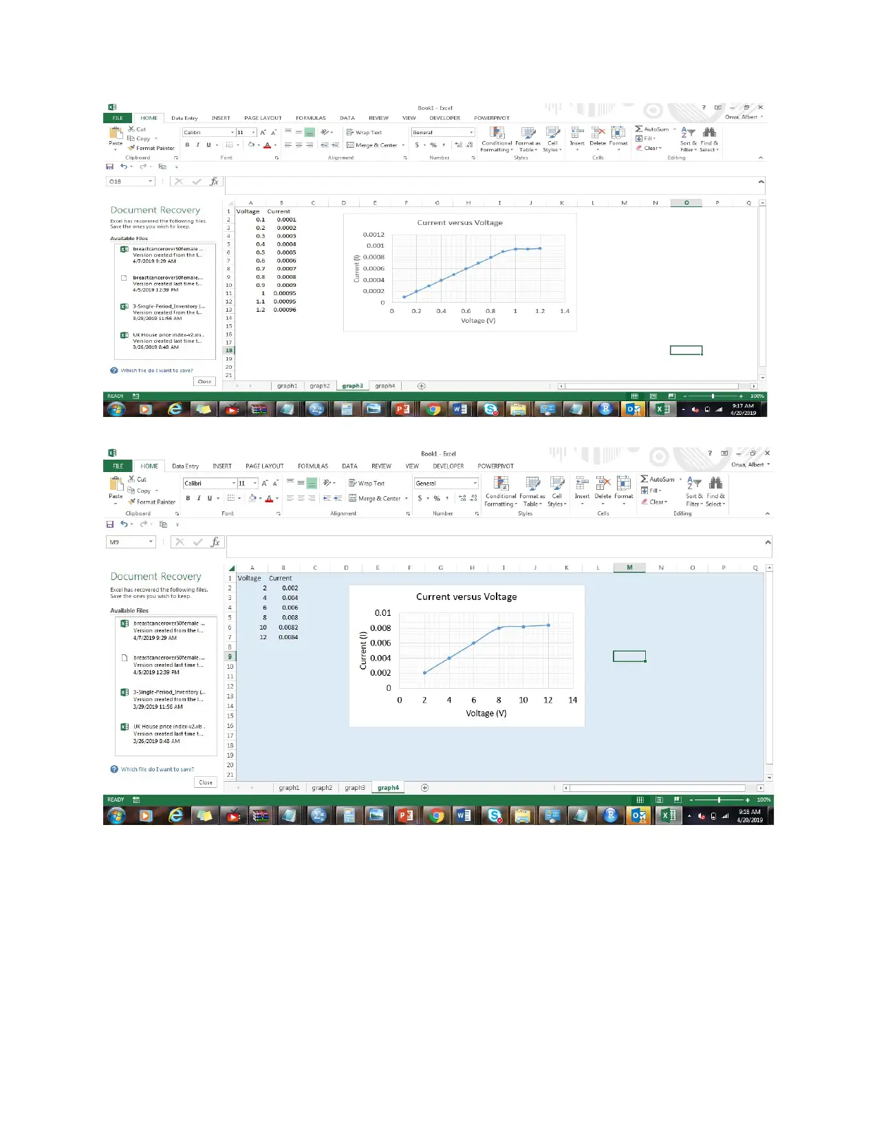
Screen grabs/shots
Paraphrase This Document
Need a fresh take? Get an instant paraphrase of this document with our AI Paraphraser
1 out of 8
Your All-in-One AI-Powered Toolkit for Academic Success.
+13062052269
info@desklib.com
Available 24*7 on WhatsApp / Email
![[object Object]](/_next/static/media/star-bottom.7253800d.svg)
Unlock your academic potential
© 2024 | Zucol Services PVT LTD | All rights reserved.
