A Comprehensive Report on Deadlock Detection and Prevention Techniques
VerifiedAdded on 2022/08/14
|10
|1836
|11
Report
AI Summary
This report delves into the critical aspects of deadlock detection and prevention within operating systems. It begins by defining starvation and explaining its detection methods. The report then addresses how deadlocks can be avoided in systems with rigid resource management. The core of the report analyzes process scheduling algorithms, including FCFS, Round Robin, SRT, and HRRN, calculating waiting time and turnaround time for each. Timeline diagrams visually represent the execution of processes under each algorithm. Furthermore, the report examines resource allocation graphs to identify and analyze deadlock scenarios, including multi-instance resources and cyclic dependencies. The report concludes by providing a safe state analysis and a discussion on deadlock recovery techniques, such as killing processes or pre-empting resources. The report references several research papers to support its findings.
Running head: DEADLOCK DETECTION AND PREVENTION
Deadlock Detection and Prevention
Name of the Student
Name of the University
Author Note
Deadlock Detection and Prevention
Name of the Student
Name of the University
Author Note
Paraphrase This Document
Need a fresh take? Get an instant paraphrase of this document with our AI Paraphraser
1DEADLOCK DETECTION AND PREVENTION
Table of Contents
Question 1 2
Question 2 2
Question 3 2
Question 4 6
Timeline diagram for FCFS: 6
Timeline diagram for Round Robin: 6
Timeline diagram for SRT: 6
Timeline diagram for HRRN: 6
Question 5 7
References 9
Table of Contents
Question 1 2
Question 2 2
Question 3 2
Question 4 6
Timeline diagram for FCFS: 6
Timeline diagram for Round Robin: 6
Timeline diagram for SRT: 6
Timeline diagram for HRRN: 6
Question 5 7
References 9
2DEADLOCK DETECTION AND PREVENTION
Question 1
In the operating system starvation is a mechanism used to carry out from a deadlock situation.
Starvation occurred when a process waited for a resource to get executed, but due to the
unavailability of the resource, the priority of the process states reducing and the process is never
getting the resource and the process never executed. The operating system can detect the above
problem of starvation by checking the number of process priority depletion and waiting time. If a
low priority process is waiting for a process which is already held by a higher priority process,
then the lower priority process has to wait for infinite time to get executed because the priority of
the process is started decreasing, and this causes starvation. It is challenging to detect starvation
in the system because all the process of the system is processed without any problem only the
victim process. Detection of the starvation process can only be done by checking the waiting time
and the priority of the process if the process has a very low priority depends on the other
processes then the chances of starvation is increased in the system, and it is possible to detect any
process are starving or not.
Question 2
a. The above system is never getting in any deadlock situation because one account only
requests for their resource from the system and if the system is rigid about all the processes of
the system like locking, updating, and unlocking. The deadlock probability is avoided if the
resource of the system works perfectly while the accounts are locked.
b. Suppose all the accounts of the system are locked at the same time, then the deadlock can be
prevented by the sequence of the rigid process of locking, updating, and unlocking regardless
of the order of the accounts being processed.
Question 3
Waiting time is a time which is spent by a process for the CPU in the ready queue. Waiting
time is calculated based on the arrival time and the completion time of the previous process. Suppose
p1 and p2 both arrive at 0ms time and the system follows FCFS. The system p0 is first allocated in
the CPU for the process execution, and p1 has to wait until p0 is not completed. So here, the waiting
time for the process p1 is the completion time of p0.
Turnaround time is the time that is taken by a process to complete the process execution to
provide the desired output. It is also used to consider the addition of total time taken from a process
to get memory allocation and total time taken to for execution. Turnaround time is used to evaluate
⊘ This is a preview!⊘
Do you want full access?
Subscribe today to unlock all pages.

Trusted by 1+ million students worldwide
3DEADLOCK DETECTION AND PREVENTION
the scheduling algorithm because it is one of the matrices of the operating system. The turnaround
time is indicated in the time unit for some systems. Turnaround time differs on application and
algorithm. The formula for calculating turnaround time is completion time – arrival time. (Kumar et
al. 2018)
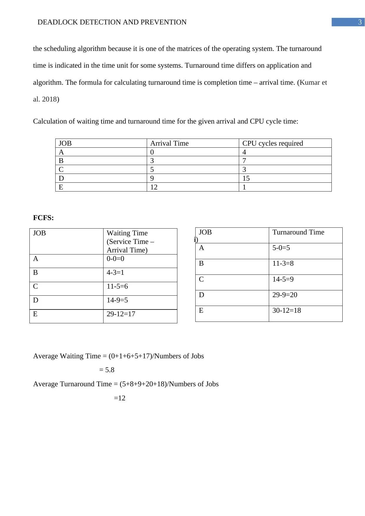
Calculation of waiting time and turnaround time for the given arrival and CPU cycle time:
JOB Arrival Time CPU cycles required
A 0 4
B 3 7
C 5 3
D 9 15
E 12 1
FCFS:
i)
Average Waiting Time = (0+1+6+5+17)/Numbers of Jobs
= 5.8
Average Turnaround Time = (5+8+9+20+18)/Numbers of Jobs
=12
JOB Waiting Time
(Service Time –
Arrival Time)
A 0-0=0
B 4-3=1
C 11-5=6
D 14-9=5
E 29-12=17
JOB Turnaround Time
A 5-0=5
B 11-3=8
C 14-5=9
D 29-9=20
E 30-12=18
Paraphrase This Document
Need a fresh take? Get an instant paraphrase of this document with our AI Paraphraser
4DEADLOCK DETECTION AND PREVENTION
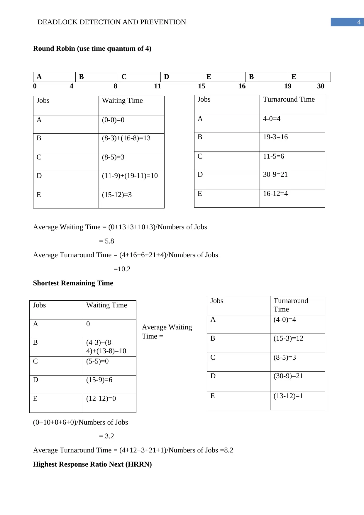
Round Robin (use time quantum of 4)
A B C D E B E
0 4 8 11 15 16 19 30
Jobs Waiting Time
A (0-0)=0
B (8-3)+(16-8)=13
C (8-5)=3
D (11-9)+(19-11)=10
E (15-12)=3
Average Waiting Time = (0+13+3+10+3)/Numbers of Jobs
= 5.8
Average Turnaround Time = (4+16+6+21+4)/Numbers of Jobs
=10.2
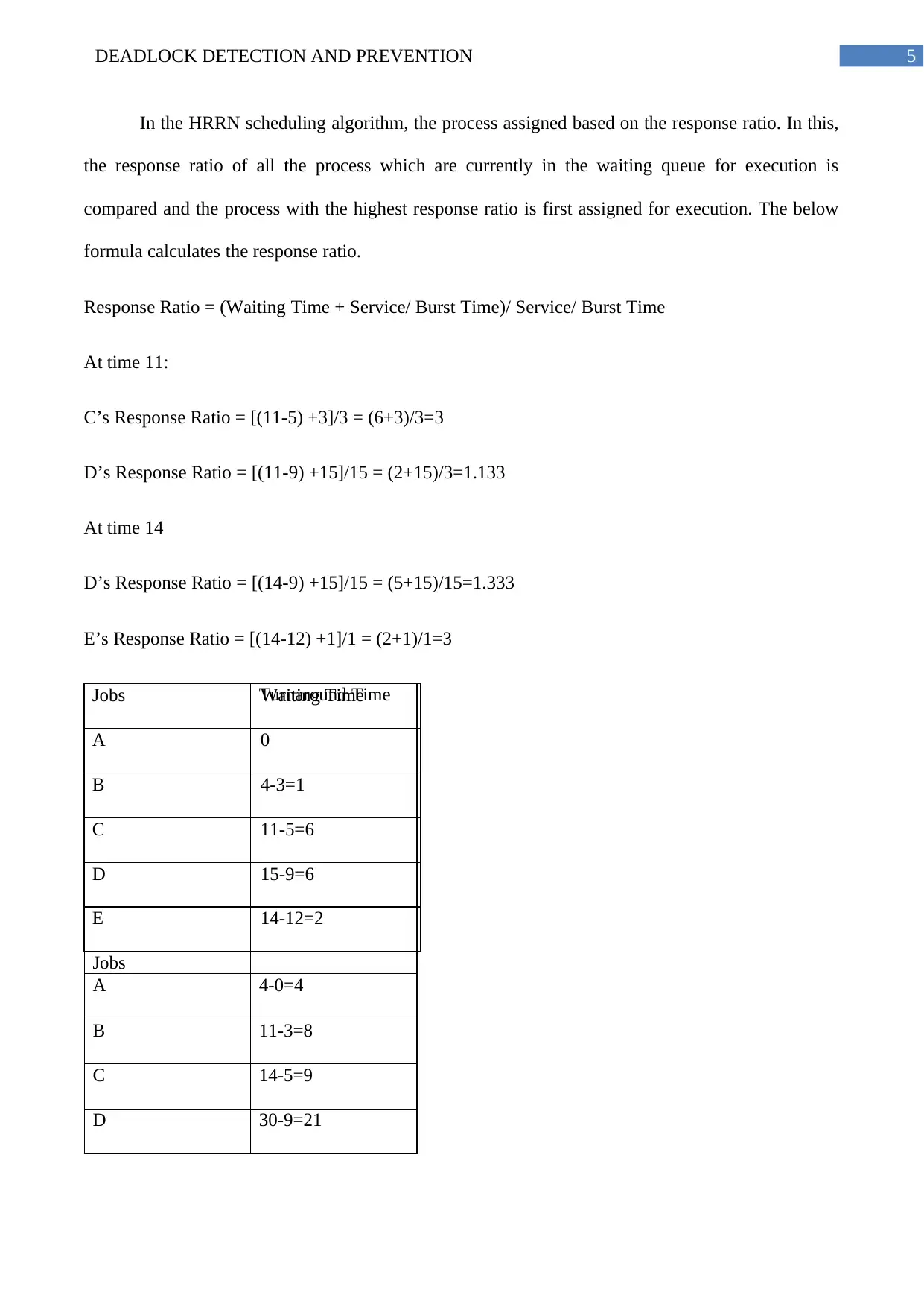
Shortest Remaining Time
Average Waiting
Time =
(0+10+0+6+0)/Numbers of Jobs
= 3.2
Average Turnaround Time = (4+12+3+21+1)/Numbers of Jobs =8.2
Highest Response Ratio Next (HRRN)
Jobs Turnaround Time
A 4-0=4
B 19-3=16
C 11-5=6
D 30-9=21
E 16-12=4
Jobs Turnaround
Time
A (4-0)=4
B (15-3)=12
C (8-5)=3
D (30-9)=21
E (13-12)=1
Jobs Waiting Time
A 0
B (4-3)+(8-
4)+(13-8)=10
C (5-5)=0
D (15-9)=6
E (12-12)=0
5DEADLOCK DETECTION AND PREVENTION
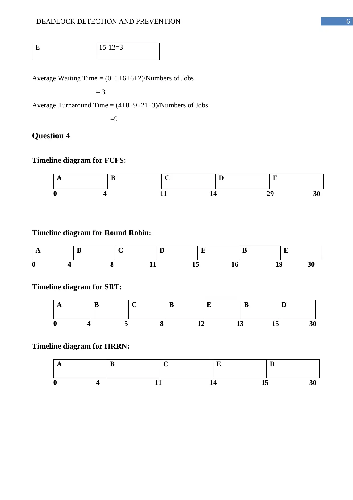
In the HRRN scheduling algorithm, the process assigned based on the response ratio. In this,
the response ratio of all the process which are currently in the waiting queue for execution is
compared and the process with the highest response ratio is first assigned for execution. The below
formula calculates the response ratio.
Response Ratio = (Waiting Time + Service/ Burst Time)/ Service/ Burst Time
At time 11:
C’s Response Ratio = [(11-5) +3]/3 = (6+3)/3=3
D’s Response Ratio = [(11-9) +15]/15 = (2+15)/3=1.133
At time 14
D’s Response Ratio = [(14-9) +15]/15 = (5+15)/15=1.333
E’s Response Ratio = [(14-12) +1]/1 = (2+1)/1=3
Jobs
Turnaround Time
A 4-0=4
B 11-3=8
C 14-5=9
D 30-9=21
Jobs Waiting Time
A 0
B 4-3=1
C 11-5=6
D 15-9=6
E 14-12=2
⊘ This is a preview!⊘
Do you want full access?
Subscribe today to unlock all pages.

Trusted by 1+ million students worldwide
6DEADLOCK DETECTION AND PREVENTION
E 15-12=3
Average Waiting Time = (0+1+6+6+2)/Numbers of Jobs
= 3
Average Turnaround Time = (4+8+9+21+3)/Numbers of Jobs
=9
Question 4
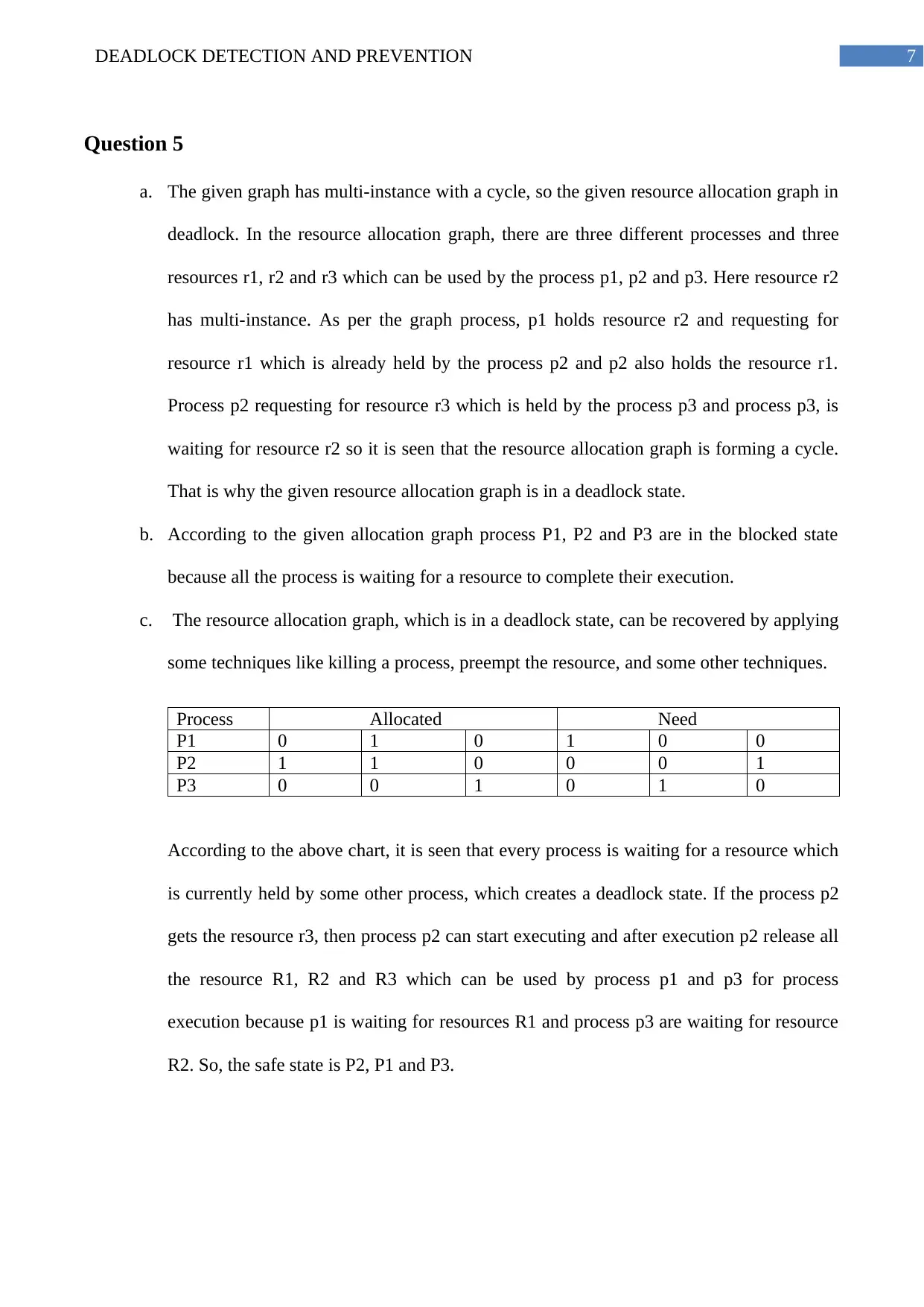
Timeline diagram for FCFS:
A B C D E
0 4 11 14 29 30
Timeline diagram for Round Robin:
A B C D E B E
0 4 8 11 15 16 19 30
Timeline diagram for SRT:
A B C B E B D
0 4 5 8 12 13 15 30
Timeline diagram for HRRN:
A B C E D
0 4 11 14 15 30
Paraphrase This Document
Need a fresh take? Get an instant paraphrase of this document with our AI Paraphraser
7DEADLOCK DETECTION AND PREVENTION
Question 5
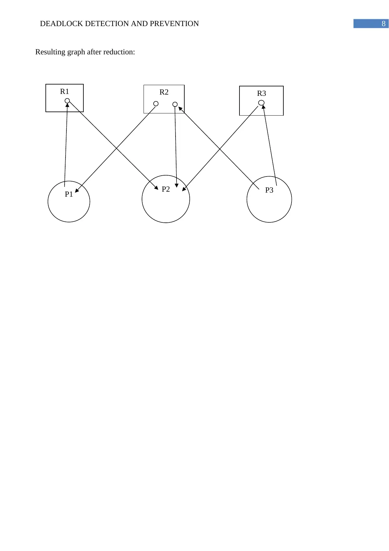
a. The given graph has multi-instance with a cycle, so the given resource allocation graph in
deadlock. In the resource allocation graph, there are three different processes and three
resources r1, r2 and r3 which can be used by the process p1, p2 and p3. Here resource r2
has multi-instance. As per the graph process, p1 holds resource r2 and requesting for
resource r1 which is already held by the process p2 and p2 also holds the resource r1.
Process p2 requesting for resource r3 which is held by the process p3 and process p3, is
waiting for resource r2 so it is seen that the resource allocation graph is forming a cycle.
That is why the given resource allocation graph is in a deadlock state.
b. According to the given allocation graph process P1, P2 and P3 are in the blocked state
because all the process is waiting for a resource to complete their execution.
c. The resource allocation graph, which is in a deadlock state, can be recovered by applying
some techniques like killing a process, preempt the resource, and some other techniques.
Process Allocated Need
P1 0 1 0 1 0 0
P2 1 1 0 0 0 1
P3 0 0 1 0 1 0
According to the above chart, it is seen that every process is waiting for a resource which
is currently held by some other process, which creates a deadlock state. If the process p2
gets the resource r3, then process p2 can start executing and after execution p2 release all
the resource R1, R2 and R3 which can be used by process p1 and p3 for process
execution because p1 is waiting for resources R1 and process p3 are waiting for resource
R2. So, the safe state is P2, P1 and P3.
8DEADLOCK DETECTION AND PREVENTION
Resulting graph after reduction:
R1 R2 R3
P1 P2 P3
Resulting graph after reduction:
R1 R2 R3
P1 P2 P3
⊘ This is a preview!⊘
Do you want full access?
Subscribe today to unlock all pages.

Trusted by 1+ million students worldwide
9DEADLOCK DETECTION AND PREVENTION
References
Alsheikhy, A., Ammar, R. and Elfouly, R., 2015, December. An improved dynamic Round Robin
scheduling algorithm based on a variant quantum time. In 2015 11th International Computer
Engineering Conference (ICENCO) (pp. 98-104). IEEE.
Bindu, C.S., Reddy, A.Y. and Reddy, P.D.K., 2017. Intelligent SRTF: A New Approach to Reduce
the Number of Context Switches in SRTF. In Proceedings of the First International Conference on
Computational Intelligence and Informatics(pp. 381-388). Springer, Singapore.
Khan, R. and Kakhani, G., 2015. Analysis of priority scheduling algorithm on the basis of FCFS &
SJF for similar priority jobs. International Journal of Computer Science and Mobile
Computing, 4(9), pp.324-331.
Kumar, S., Kumar, G., Jain, K. and Jain, A., 2018. An approach to reduce turn around time and
waiting time by the selection of round robin and shortest job first algorithm. International Journal of
Engineering & Technology, 7(2.8), pp.667-672.
Ng, N. and Yoshida, N., 2016, March. Static deadlock detection for concurrent go by global session
graph synthesis. In Proceedings of the 25th International Conference on Compiler Construction (pp.
174-184).
Shidali, G.A., Junaidu, S.B. and Abdullahi, S.E., 2015. A new hybrid process scheduling algorithm
(pre-emptive modified highest response ratio next). Computer Science and Engineering, 5(1), pp.1-7.
Shousha, M., Briand, L. and Labiche, Y., 2010. A uml/marte model analysis method for uncovering
scenarios leading to starvation and deadlocks in concurrent systems. IEEE transactions on Software
Engineering, 38(2), pp.354-374.
1 out of 10
Related Documents
Your All-in-One AI-Powered Toolkit for Academic Success.
+13062052269
info@desklib.com
Available 24*7 on WhatsApp / Email
![[object Object]](/_next/static/media/star-bottom.7253800d.svg)
Unlock your academic potential
Copyright © 2020–2026 A2Z Services. All Rights Reserved. Developed and managed by ZUCOL.


