Deep Drawing of Cup Shape and Plunge Cutting using Lead Plate and its FEM Simulation
VerifiedAdded on 2023/06/04
|10
|1835
|346
AI Summary
This report discusses the project of Deep Drawing of Cup Shape and Plunge Cutting using Lead Plate and its FEM Simulation. The report covers the objectives, area of work, distinctive activity, identified issues and their solutions, and project review. The proposed project could be efficient and effective enough in drawing the exact shape of the cup in single stroke. The materials used for the development of the cups are brass and pure aluminium. The FEA simulation helped in validating the research being drawn in the above experiment for the conventional deep drawing.
Contribute Materials
Your contribution can guide someone’s learning journey. Share your
documents today.
COMPETENCY
DEMONSTRATION REPORT
Career Episode 3
DEMONSTRATION REPORT
Career Episode 3
Secure Best Marks with AI Grader
Need help grading? Try our AI Grader for instant feedback on your assignments.
CE 3.1 Project Information
Name of the project: Deep Drawing of cup shape and plunge cutting using lead plate
and its FEM simulation
Location of the project: [PLEASE FILL]
Project Duration: [PLEASE FILL]
Organization: [PLEASE FILL]
Role and Designation during the time: Team Leader
CE 3.2 Project Background
CE 3.2.1 Characteristics of the project
I identified that the cup manufacturing companies are lagging in developing the exact
model of the cups through the application of the different cross-section shapes shaft. I proposed a
new process for enhancing the deep draw ability of the drawn triangular cross section, star, rose,
and clover cups. The proposed project could be efficient and effective enough in drawing the
exact shape of the cup in single stroke. The materials used for the development of the cups are
brass and pure aluminium. I performed the experimental verification and numerical analysis in
manner to propose the efficiency of the proposed technique. I used FEA (Finite Element
analysis) for proving the development of four different cross-section cups in different shapes. I
noted that the cup height and Limiting Drawing Ratio (LDR) have been approximately larger as
compared to that of the conventional deep drawing process. I successfully produced the star cups
with LDR’s 3.37 for Aluminum and 3.44 for Brass.
CE 3.2.2 Objectives developed for the project
Following set of objectives were developed for the successful and efficient delivery of
the proposed project:
To analyse and confirm the proposed technique for developing star shape cup
experimentally and demonstrating the efficiency of the developed product using quantitative
results.
To utilize the FEA for proving the efficiency of the proposed technique
To install and configure the proposed technique within the existing system of the
organization
To experiment on the existing process of the deep cup drawing and propose the efficient
and effective results.
CE 3.2.3 My area of work
I proposed the method for drawing asymmetric cups through pushing the circular blank
as per the desired punch design. I selected a conical die shape for the proceeding with the project
that has a half cone angle of a = 18 degree. In manner to draw the different shapes of the cups
being drawn, different cross-sections of the conical shape could be integrated within the shaft.
The cup drawing process partially include the drawn frustum cup at the cupping stage,
asymmetric cup drawing stage and the complete asymmetric cup’s formation. I proposed the
technique that can be helpful in reducing the deformation velocities within the orifice compared
to the conventional technique. The desired cross-section could be used for punching the material
and pushing the bottom of the frustum cup in manner to get the desired cross-section of the
conical die that can alternatively result in drawing of the cup of size 2 mm and 3 mm. I also
managed the project in an effective and efficient way through using my leadership and
management qualities. I used leadership technique for assuring that the project could be
delivered within the expected time and leadership qualities in motivating every individuals
involved in the project.
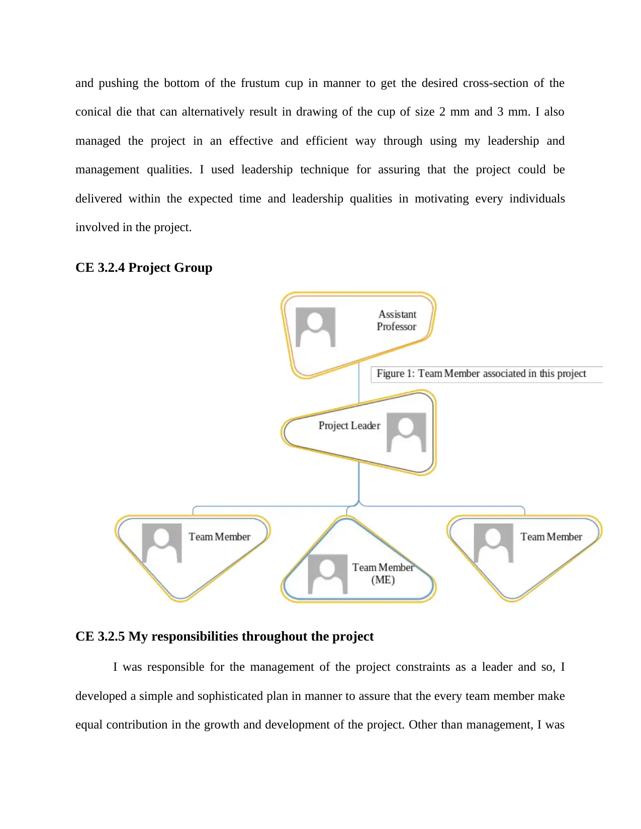
CE 3.2.4 Project Group
CE 3.2.5 My responsibilities throughout the project
I was responsible for the management of the project constraints as a leader and so, I
developed a simple and sophisticated plan in manner to assure that the every team member make
equal contribution in the growth and development of the project. Other than management, I was
conical die that can alternatively result in drawing of the cup of size 2 mm and 3 mm. I also
managed the project in an effective and efficient way through using my leadership and
management qualities. I used leadership technique for assuring that the project could be
delivered within the expected time and leadership qualities in motivating every individuals
involved in the project.
CE 3.2.4 Project Group
CE 3.2.5 My responsibilities throughout the project
I was responsible for the management of the project constraints as a leader and so, I
developed a simple and sophisticated plan in manner to assure that the every team member make
equal contribution in the growth and development of the project. Other than management, I was
Secure Best Marks with AI Grader
Need help grading? Try our AI Grader for instant feedback on your assignments.
also assigned to the identification of the efficient method that could be helpful in assuring the
effective and efficient delivery of the proposed project technique. I calculated the deep drawing
ratio DR of the asymmetric cups for every cross section and the necessary calczulations using the
following formula:
A constant gap clearance ratio c/t0 =1.5 between die/blank and die/punch holder interface
surfaces as I adopted these during the FE simulation.
The asymmetric cups’ deep drawing ratio can be defined by:
DR 0.5Do Am ……………………….. (1)
The principle stated by constancy of volume, the depth of the cup, h can be calculated as:
h Ao Am Cm………………………… (2)
Where, Ao and Do are the area and diameter of the initial circular blank respectively, Am
is the die cavity’s and punch’s mean cross section.
The Cm is the die cavity’s and punch’s mean cross-section periphery. In manner to
analyze the possibilities of comparing the four shapes
Die fillet radius = 5 mm,
Die half cone angle (α) = 180,
Punch profile radius = 4mm,
Relative die clearance (c/to) = 1.25,
Die throat length = 2 mm;
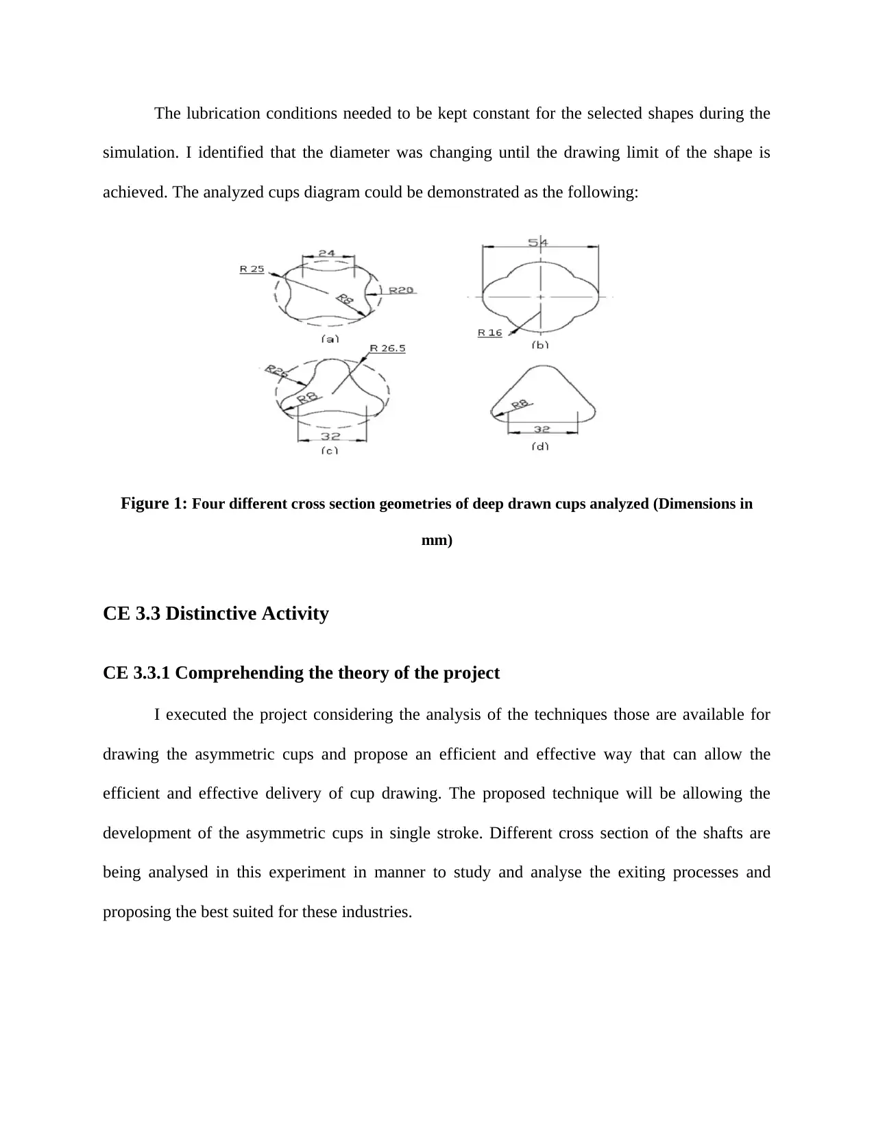
The lubrication conditions needed to be kept constant for the selected shapes during the
simulation. I identified that the diameter was changing until the drawing limit of the shape is
achieved. The analyzed cups diagram could be demonstrated as the following:
Figure 1: Four different cross section geometries of deep drawn cups analyzed (Dimensions in
mm)
CE 3.3 Distinctive Activity
CE 3.3.1 Comprehending the theory of the project
I executed the project considering the analysis of the techniques those are available for
drawing the asymmetric cups and propose an efficient and effective way that can allow the
efficient and effective delivery of cup drawing. The proposed technique will be allowing the
development of the asymmetric cups in single stroke. Different cross section of the shafts are
being analysed in this experiment in manner to study and analyse the exiting processes and
proposing the best suited for these industries.
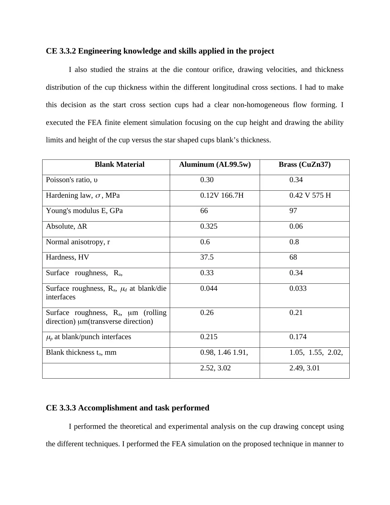
CE 3.3.2 Engineering knowledge and skills applied in the project
I also studied the strains at the die contour orifice, drawing velocities, and thickness
distribution of the cup thickness within the different longitudinal cross sections. I had to make
this decision as the start cross section cups had a clear non-homogeneous flow forming. I
executed the FEA finite element simulation focusing on the cup height and drawing the ability
limits and height of the cup versus the star shaped cups blank’s thickness.
Blank Material Aluminum (AL99.5w) Brass (CuZn37)
Poisson's ratio, υ 0.30 0.34
Hardening law,
, MPa 0.12V 166.7H 0.42 V 575 H
Young's modulus E, GPa 66 97
Absolute, R 0.325 0.06
Normal anisotropy, r 0.6 0.8
Hardness, HV 37.5 68
Surface roughness, Ra, 0.33 0.34
Surface roughness, Ra,
d at blank/die
interfaces
0.044 0.033
Surface roughness, Ra, m (rolling
direction) m(transverse direction)
0.26 0.21
p at blank/punch interfaces 0.215 0.174
Blank thickness to, mm 0.98, 1.46 1.91, 1.05, 1.55, 2.02,
2.52, 3.02 2.49, 3.01
CE 3.3.3 Accomplishment and task performed
I performed the theoretical and experimental analysis on the cup drawing concept using
the different techniques. I performed the FEA simulation on the proposed technique in manner to
Paraphrase This Document
Need a fresh take? Get an instant paraphrase of this document with our AI Paraphraser
assure that the developed project is efficient and effective enou7gth for the management and
delivery of the respective research. I lead the team towards a concentric set of objectives and
goals for the management and delivery of the project within the estimated timeline and budget.
CE 3.3.4 Identified issues and their solutions
3.3.4.1 Issues
I identified that the star model shaft would be much more complex than the other selected
models for the cup. The strategies needed to be prepared very early stage of the project in
manner to make sure that the project delivery is being made in an efficient and effective manner.
Team management was very crucial for the successful delivery of the project as it was noticed
throughout the project that the plans were being failed and the team members were not being
involved in the project.
3.3.4.2 Solutions
I performed the FEA simulation in manner to propose a sophisticated way that could be
efficient and effective enough for the management and delivery of the necessary project
deliverables. I proposed a risk management plan along with the timeline and budget plan.
However, the project was already started and thus, for making the proposed plan successful, I
introduced it to the team members.
CE 3.3.5 Plan to produce creative and innovative work
I adapted the mesh refinement in manner to apply them in every simulation during
studying the assessment in manner to overcome the quantitative divergence that was caused by
the highly distorted regions. Punch and die were modeled in the form of the rigid bodies. I
analyzed the asymmetric cup drawing on the basis of the various geometries as considered
during the deep drawing cup parts. I used the four asymmetric cups those had unique cross-
sections including: star, clover, rose, and triangle. Normal anisotropy ‘r’ was used for
representing the anisotropic behavior of blank materials. I kept the clearance ratio c/t0 =1.25 as a
constant in between the punch and the die. The Fe simulation helped in validating the research
being drawn in the above experiment for the conventional deep drawing. I also adopted the
constant gap clearance ratio c/t0 =1.5 between die/blank and die/punch holder interface surfaces
during the FEA simulation.
CE 3.3.6 Collaborative work
I was assigned to the technical and management sector along with the responsibility of
the team management. Leading a team was not very tough, as I had already utilized my
leadership and management technique for the delivery of the project. Every team member made
equal contribution in the development and execution of this project through accomplishing the
deliverables of the project those was estimated to be in different phases. I made sure that the
team should be contributing equally in the growth and development of the project through
delivering every possible activities and phases of the project.
CE 3.4 Project Review
CE 3.4.1 Project Overview and contribution
The above experiment was successful in drawing the conclusion that the star shaped
asymmetric cups could be prepared through single stroke. The FEA simulation helped in
validating the star shaped asymmetric cups. The proposed project could be efficient and effective
enough in drawing the exact shape of the cup in single stroke. The materials used for the

development of the cups are brass and pure aluminium. I performed the experimental verification
and numerical analysis in manner to propose the efficiency of the3 proposed technique.
and numerical analysis in manner to propose the efficiency of the3 proposed technique.
1 out of 10
Your All-in-One AI-Powered Toolkit for Academic Success.
+13062052269
info@desklib.com
Available 24*7 on WhatsApp / Email
![[object Object]](/_next/static/media/star-bottom.7253800d.svg)
Unlock your academic potential
© 2024 | Zucol Services PVT LTD | All rights reserved.