UET Peshawar CE-402: Barrage Components and Seepage Theories
VerifiedAdded on 2023/02/06
|38
|4121
|84
Report
AI Summary
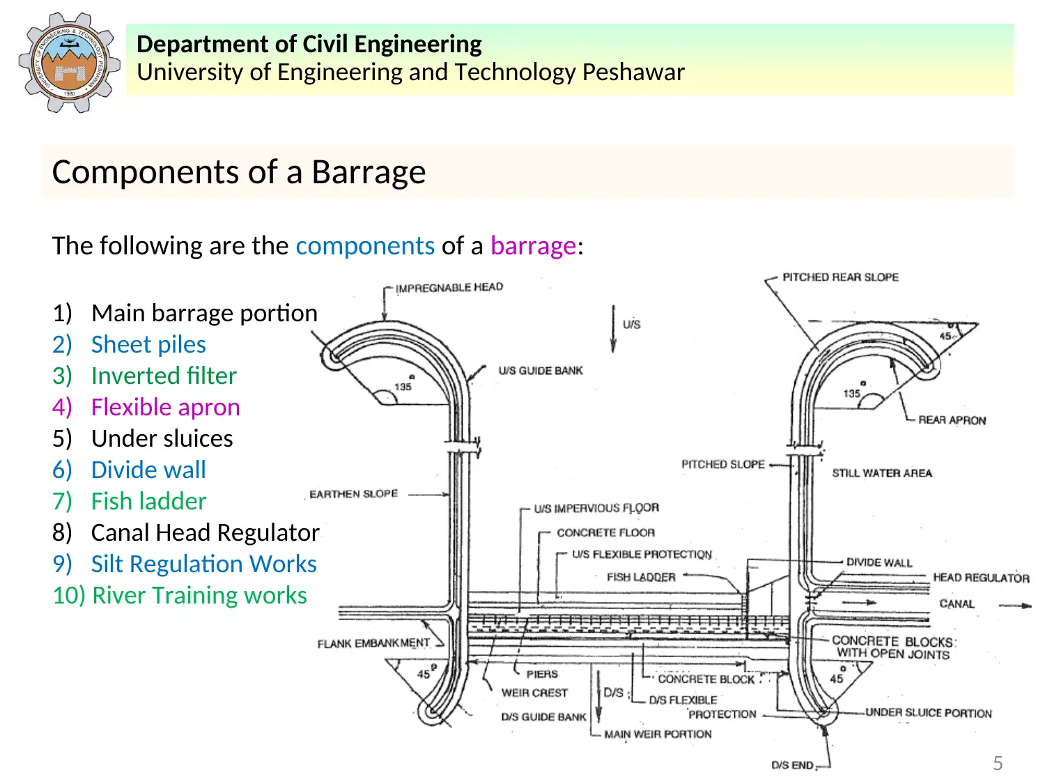
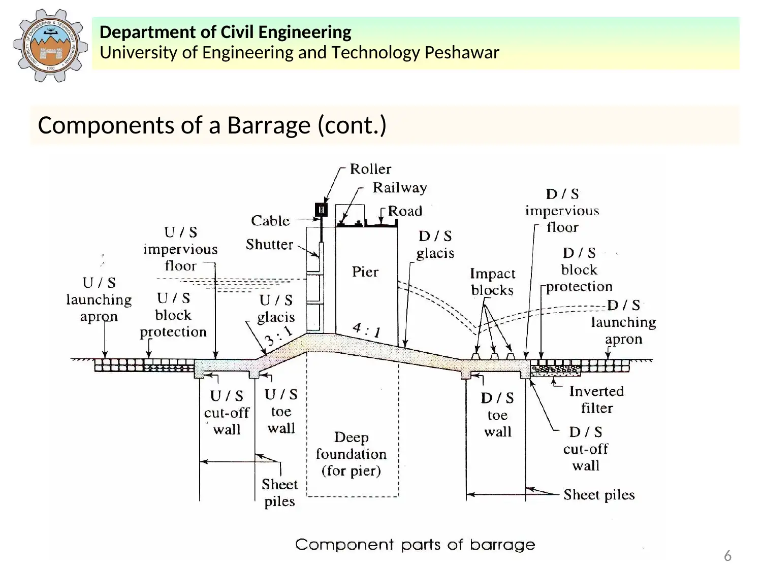
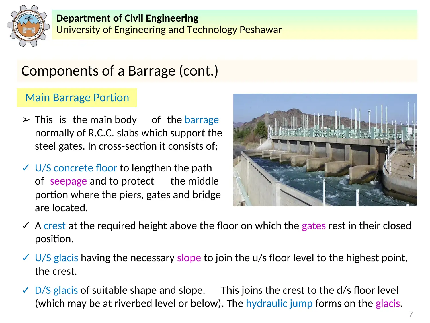
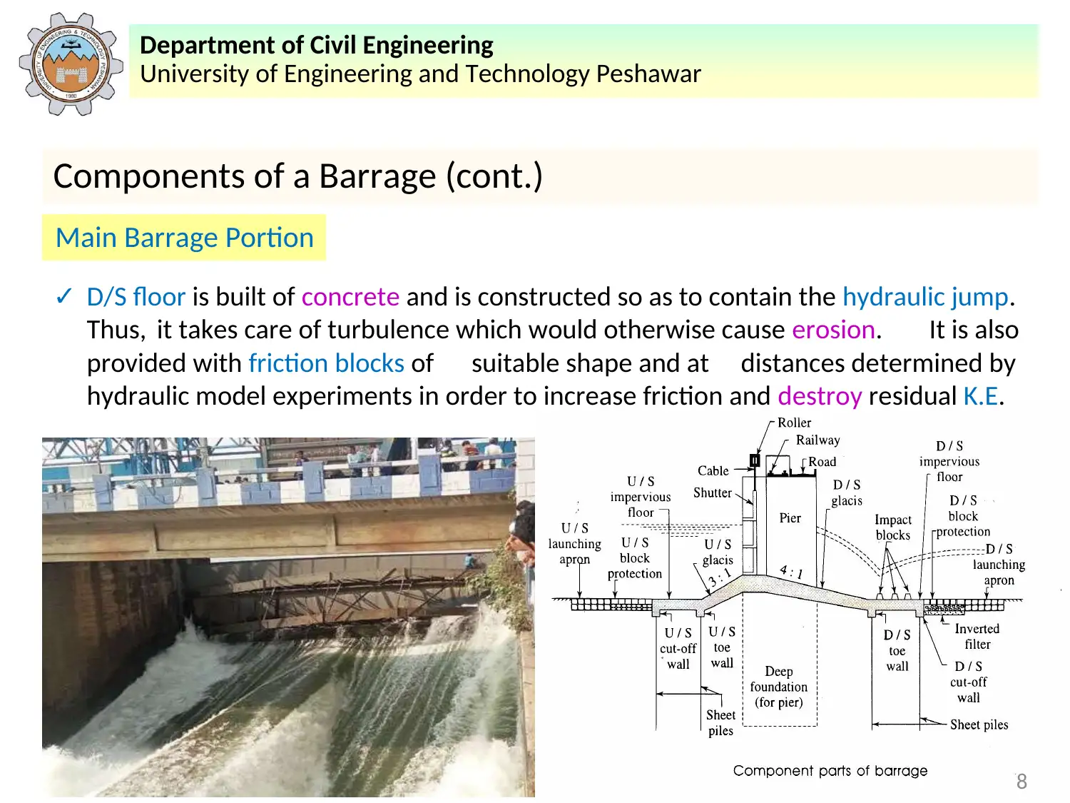
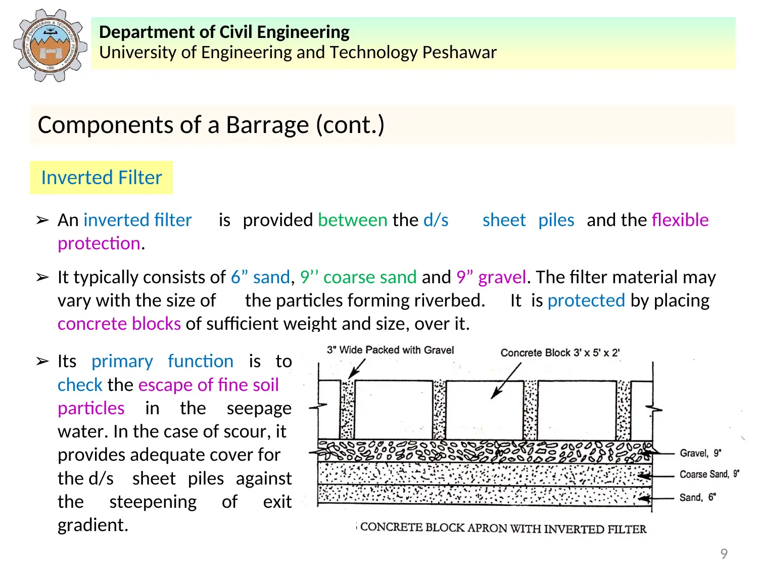
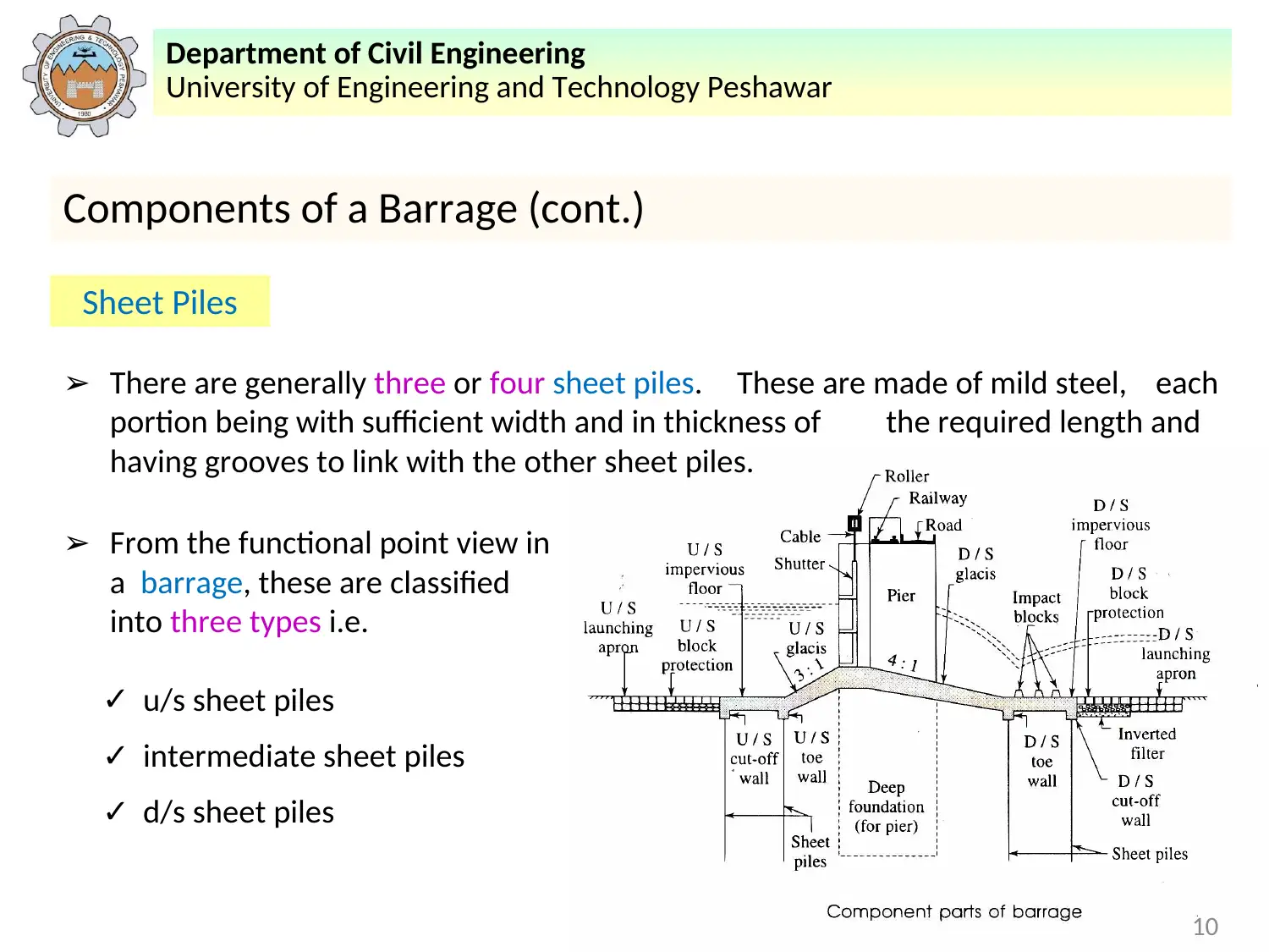
This report, prepared for the Civil Engineering course CE-402 at the University of Engineering and Technology Peshawar, focuses on the components and operational aspects of barrages. It begins by defining a barrage and its function as a river regulator, contrasting it with weirs. The report then details the various components of a barrage, including the main barrage portion, sheet piles, inverted filters, flexible aprons, under sluices, divide walls, fish ladders, canal head regulators, silt regulation works, and river training works. Each component's function is thoroughly explained. Furthermore, the report explores the causes of failure in weirs and barrages on permeable foundations, categorizing failures due to subsurface flow (piping or undermining, uplift pressure) and surface flow (hydraulic jump, scouring). Precautions against these failures, such as proper design of the impervious layer, use of sheet piles, and energy dissipaters, are also discussed. Finally, it introduces the theories of seepage and their importance in the design of hydraulic structures like barrages. This report provides comprehensive information on the design, operation, and potential failures of barrages, making it a valuable resource for civil engineering students.
1 out of 38

Your All-in-One AI-Powered Toolkit for Academic Success.
+13062052269
info@desklib.com
Available 24*7 on WhatsApp / Email
![[object Object]](/_next/static/media/star-bottom.7253800d.svg)
Copyright © 2020–2026 A2Z Services. All Rights Reserved. Developed and managed by ZUCOL.