Design, Modeling and Structural Analysis of Piston - Hero Splendor
VerifiedAdded on 2023/05/28
|23
|3636
|230
Report
AI Summary
This report presents a comprehensive design and analysis of a piston for a 4-stroke petrol engine, specifically for a Hero Splendor Pro bike. The design process involves determining various piston dimensions using analytical methods under maximum power conditions, considering the combined effects of mechanical and thermal loads. The report includes a detailed nomenclature of the piston, covering the piston head, rings, skirt, and pin, along with design considerations, material selection (cast aluminum alloy), and potential failure modes. The piston is modeled using CATIA, and structural analysis is performed, likely using ANSYS, to evaluate stress distribution and overall performance. The report also includes a comparison of the designed piston's dimensions with the original piston dimensions used in the bike. Desklib offers a platform to explore this and similar mechanical engineering assignments.
DESIGN PROJECT REPORT
Submitted by
BONAFIDE CERTIFICATE
Certified that this project report is the bonafide work of ...... .......
Who carried out the research under my supervision Certified further, that to the best
of my knowledge the work reported herein does not form part of any other project.
SIGNATURE SIGNATURE
1
Submitted by
BONAFIDE CERTIFICATE
Certified that this project report is the bonafide work of ...... .......
Who carried out the research under my supervision Certified further, that to the best
of my knowledge the work reported herein does not form part of any other project.
SIGNATURE SIGNATURE
1
Paraphrase This Document
Need a fresh take? Get an instant paraphrase of this document with our AI Paraphraser
ABSTRACT
Piston is the part of engine which converts heat and pressure energy liberated by fuel
combustion into mechanical works. Engine piston is the most complex component
among the automotive. An illustrate design procedure for a piston for 4 stroke petrol
engine for hero splendor – pro bike and its analysis by its comparison with original
piston dimensions used in bike. The design procedure involves determination of
various piston dimensions using analytical method under maximum power condition.
In this paper the combined effect of mechanical and load is taken into consideration
while determining various dimensions. The basic data of the engine are taken from a
located engine type of hero splendor –pro bike.
2
TABLE OF CONTENTS
CHAPTER TITLE PAGE
ABSTRACT III
TABLE OF CONTENTS IV
LIST OF TABLES VI
LIST OF FIGURES VII
1. INTRODUCTION
1.1 Objectives 02
1.2 major force acting over the piston 03
1.3functions of piston 03
1.4 factor considering for proper functioning the piston 03
1.5 model of piston 04
2. DESIGN AND PROPERTICS
2.1 Nomenclature Of Piston 06
2.1.1 Piston Head 06
2.1.2 Piston Ring 07
2.1.3 Piston Skirt 07
2.1.4 Piston Pin 08
2.2 Design Consideration Of Piston 08
2.3 Piston Function Design Requirement 08
2.4 Piston Structural Design Requirement 09
2.5 Material For Piston 09
2.6 Failure Modes Of Piston 10
2.6.1 Rough Out Failure 11
2.6.1.1 Damage From Unmixed Fuel 11
2.6.1.2 Damage From Over Speeding
Engine
2.6.1.3 Damage From Detonation 12
2.6.1.4 Damage From Heat Seizure 13
2.6.2 Wrong Out Failure 13
2.6.2.1 Damage From Getting Through The 13
Air Filter
2.6.2.2 Damage From Bearing Failure 14
3
⊘ This is a preview!⊘
Do you want full access?
Subscribe today to unlock all pages.
Trusted by 1+ million students worldwide
3. MODELLING OF PISTON
3.1 Technical Speciation’s 16
3.2 Theoretical Calculation Of Piston 16-22
3.3 Piston Modeling in CATIA 23
4 DESIGN ANALYSIS 21
4.1 Piston Model 22
4.2 Structural Analysis Of Piston 22-25
4.3 code input
5 RESULT & DISCUSSIONS 30
5.1 Conclusion 31
5.2 Further p
4
3.1 Technical Speciation’s 16
3.2 Theoretical Calculation Of Piston 16-22
3.3 Piston Modeling in CATIA 23
4 DESIGN ANALYSIS 21
4.1 Piston Model 22
4.2 Structural Analysis Of Piston 22-25
4.3 code input
5 RESULT & DISCUSSIONS 30
5.1 Conclusion 31
5.2 Further p
4
Paraphrase This Document
Need a fresh take? Get an instant paraphrase of this document with our AI Paraphraser
LIST OF TABLES
TABLE
NO.
TITLE PAGE
NO.
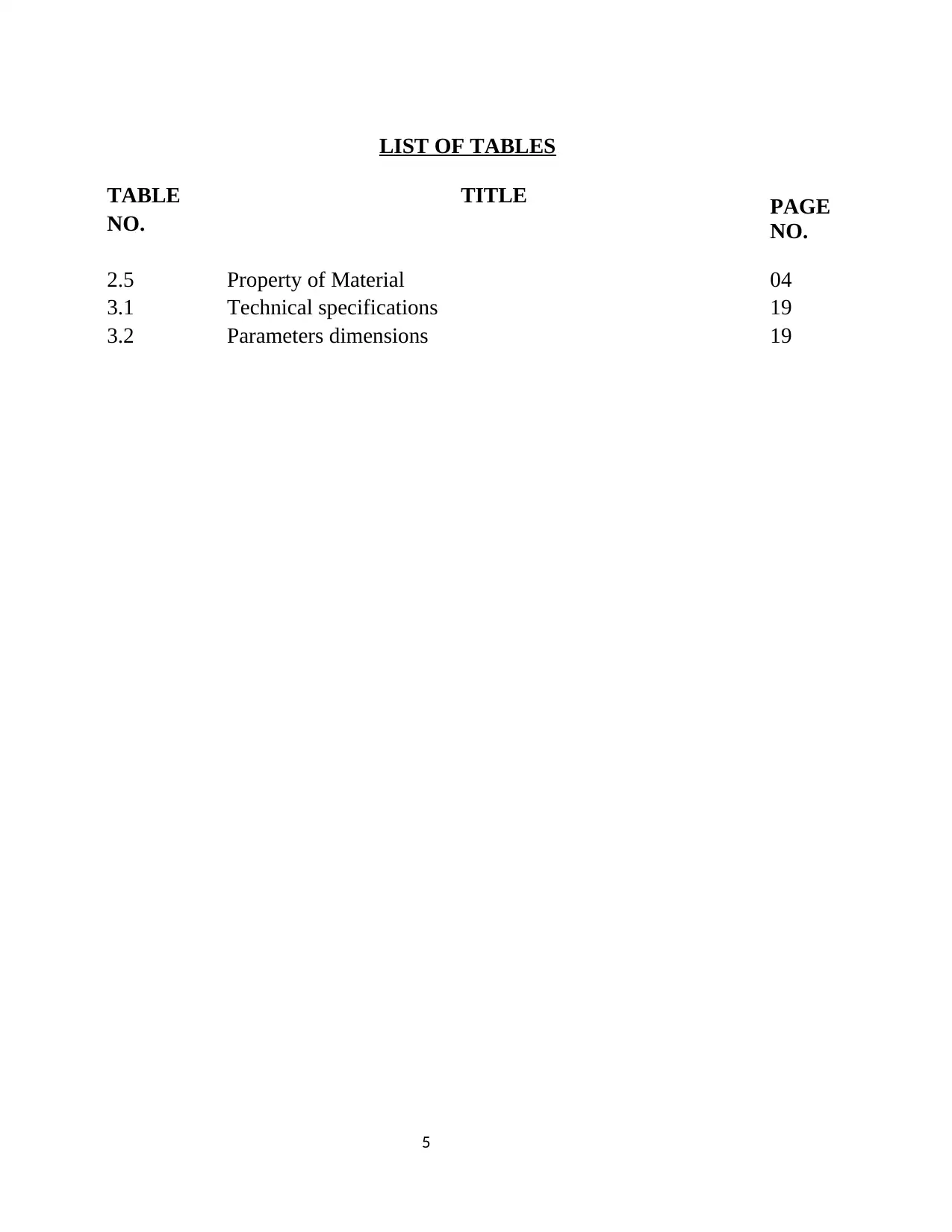
2.5 Property of Material 04
3.1 Technical specifications 19
3.2 Parameters dimensions 19
5
TABLE
NO.
TITLE PAGE
NO.
2.5 Property of Material 04
3.1 Technical specifications 19
3.2 Parameters dimensions 19
5
LIST OF FIGURES
FIGURE FIGURE NAME PAGE
NO. NO.
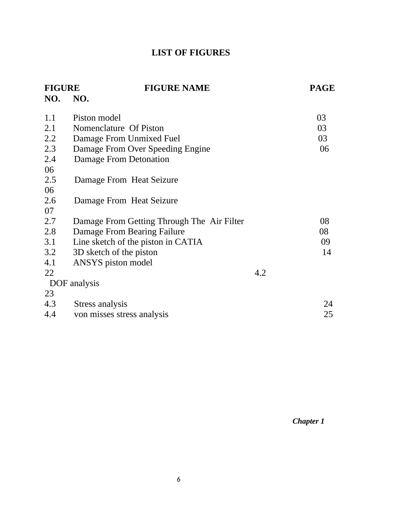
1.1 Piston model 03
2.1 Nomenclature Of Piston 03
2.2 Damage From Unmixed Fuel 03
2.3 Damage From Over Speeding Engine 06
2.4 Damage From Detonation
06
2.5 Damage From Heat Seizure
06
2.6 Damage From Heat Seizure
07
2.7 Damage From Getting Through The Air Filter 08
2.8 Damage From Bearing Failure 08
3.1 Line sketch of the piston in CATIA 09
3.2 3D sketch of the piston 14
4.1 ANSYS piston model
22 4.2
DOF analysis
23
4.3 Stress analysis 24
4.4 von misses stress analysis 25
Chapter 1
6
FIGURE FIGURE NAME PAGE
NO. NO.
1.1 Piston model 03
2.1 Nomenclature Of Piston 03
2.2 Damage From Unmixed Fuel 03
2.3 Damage From Over Speeding Engine 06
2.4 Damage From Detonation
06
2.5 Damage From Heat Seizure
06
2.6 Damage From Heat Seizure
07
2.7 Damage From Getting Through The Air Filter 08
2.8 Damage From Bearing Failure 08
3.1 Line sketch of the piston in CATIA 09
3.2 3D sketch of the piston 14
4.1 ANSYS piston model
22 4.2
DOF analysis
23
4.3 Stress analysis 24
4.4 von misses stress analysis 25
Chapter 1
6
⊘ This is a preview!⊘
Do you want full access?
Subscribe today to unlock all pages.
Trusted by 1+ million students worldwide
1 INTRODUCTION
Piston is one of n the mechanical component, piston invented in a German scientist
Nicholas August Otto in year 1866. Piston is considered to be one of the most important
parts in a reciprocating Engine, reciprocating pumps, gas compressors and pneumatic
cylinders, among other similar mechanisms in which it helps to convert the chemical energy
obtained by the combustion of fuel into useful (work) mechanical power. The purpose of the
piston is to provide a means of conveying the expansion of gases to the crankshaft via
connecting rod, The piston acts as a movable end of the combustion chamber Piston is
essentially a cylindrical plug that moves up & down in the cylinder It is equipped with piston
rings to provide a good seal between the cylinder wall,
1.1Objectives of the project are as follows
1. To develop structural modeling of piston
2. To develop structural analysis of the piston
1.2 Major Force Acting Over Piston
1. Due to explosion of fuel gases
2. Due to compression of fuel gases
3. Side wall friction and forces
4. Thermal load
5. Inertia force due to high frequency of reciprocation of piston
6. Friction and forces at crank pin hole
1.3 Functions Of Piston
1. To reciprocate in the cylinder as a gas tight plug causing suction, Compression,
expansion, and exhaust strokes.
7
Paraphrase This Document
Need a fresh take? Get an instant paraphrase of this document with our AI Paraphraser
2. To receive the thrust generated by the explosion of the gas in the cylinder and
transmit it to the connecting rod.
3.To form a guide and bearing to the small end of the connecting rod and to take
the side thrust due to obliquity of the rod.
1.4 Factors Considered For Proper Functioning Of Piston
1. The piston should have enormous strength and heat resistance properties to
withstand gas pressure and inertia forces. They should have minimum weight to
minimize the inertia forces.
2. The material of the piston should have good and quick dissipation of heat from the
crown to the rings and bearing area to the cylinder walls. It should form an
effective gas and oil seal.
3. Material of the piston must possess good wearing qualities, so that the piston is
able to maintain sufficient surface-hardness unto the operating temperatures.
4. Piston should have rigid construction to withstand thermal, mechanical distortion
and sufficient area to prevent undue wear. It has even expansion under thermal
loads so should be free as possible from discontinuities
1.5 Piston Assemble Model
DESIGN AND PROPERTIES
2.1 Nomenclature of Piston
2.1.1 Piston Head or Crown
The piston head or crown is designed keeping in view the following two main considerations, i.e.
1. It should have adequate strength to withstand the straining action due to
pressure of explosion inside the engine cylinder, and
8
2. It should dissipate the heat of combustion to the cylinder walls as quickly as
possible. On the basis of first consideration of straining action, the thickness
of the piston head is determined by treating it as a flat circular plate of
uniform thickness, fixed at the outer edges and subjected to a uniformly
distributed load due to the gas pressure over the entire Cross-section.
2.1.2 Piston Rings
The piston rings are used to impart the necessary radial pressure to maintain
the seal between the piston and the cylinder bore. These are usually made of
grey cast iron or alloy cast iron because of their good wearing properties and
also they retain spring characteristics even at high temperatures.
The piston rings are of the following two types:
1. Compression rings or pressure rings, and
2. Oil control rings or oil scraper.
The compression rings or pressure rings are inserted in the grooves at the top portion
of the piston and may be three to seven in number. These rings also transfer heat
from the piston to the cylinder liner and absorb some part of the piston fluctuation
due to the side thrust. The oil control rings or oil scrapers are provided below the
compression rings. These rings provide proper lubrication to the liner by allowing
sufficient oil to move up during upward stroke and at the same time scrap the
lubricating oil from the surface of the liner in order to minimize the flow of the oil
to the combustion chamber.
The compression rings are usually made of rectangular cross-section and the
diameter of the ring is slightly larger than the cylinder bore. A part of the ring is cut-
off in order to permit it to go into the cylinder against the liner wall. The gap
between the ends should be sufficiently large when the ring is put cold so that even
at the highest temperature, the ends do not touch each other when the ring expands,
otherwise there might be buckling of the ring.
2.1.3 Piston Skirt
The portion of the piston below the ring section is known as piston skirt. In
acts as a bearing for the side thrust of the connecting rod. The length of the piston
9
⊘ This is a preview!⊘
Do you want full access?
Subscribe today to unlock all pages.
Trusted by 1+ million students worldwide
skirt should be such that the bearing pressure on the piston barrel due to the side
thrust does not exceed0.25 N/mm2 of the projected area for low speed engines and
0.5 N/mm2 for high speed engines. It may be noted that the maximum thrust will be
during the expansion stroke. The side thrust (R) on the cylinder liner is usually taken
as 1/10 of the maximum gas load on the piston.
2.1.4 Piston Pin
The piston pin (also called gudgeon pin or wrist pin) is used to connect the
piston and the connecting rod. It is usually made hollow and tapered on the inside,
the smallest inside diameter being at the center of the pin. The piston pin passes
through the bosses provided on the inside of the piston skirt and the bush of the
small end of the connecting rod. The Centre of piston pin should be 0.02 D to 0.04
D above the center of the skirt, in order to off-set the turning effect of the friction
and to obtain uniform distribution of pressure between the piston and the cylinder
liner. The material used for the piston pin is usually case hardened steel alloy
containing nickel, chromium, molybdenum or vanadium having tensile strength
from 710 MPa to 910 MPa.
2.2 Design Considerations of a Piston
In designing a piston for I.C. engine, the following points should be taken into
consideration
1. It should have enormous strength to withstand the high gas pressure and inertia forces.
2. It should have minimum mass to minimize the inertia forces.
3. It should form an effective gas and oil sealing of the cylinder.
4. It should provide sufficient bearing area to prevent undue wear.
5. It should disperse the heat of combustion quickly to the cylinder walls.
6. It should have high speed reciprocation without noise.
10
Paraphrase This Document
Need a fresh take? Get an instant paraphrase of this document with our AI Paraphraser
7. It should be of sufficient rigid construction to withstand thermal and mechanical
distortion.
8. It should have sufficient support for the piston pin.
2.3 Piston Function Design Requirement
1. Easily move to the reciprocating motion inside of cylinder
2. Reducing friction between the connecting rod and piston pin
3. There is no strain occurring the piston pin
4. Piston move even at minimum pressure
2.4 Piston Structural Design Requirement
1. Piston designed in cylindrical shape because easily
Move to the up & down direction
2. Piston should be a compact size
3. Piston head geometry (curve, flat) should be in correct shape so that in gives maximum
efficiency
2.5 Material for Pistons
The most commonly used materials for pistons of I.C. engines are cast iron,
cast aluminum, forged aluminum, cast steel and forged steel. The cast iron pistons
are used for moderately rated engines with piston speeds below 6 m / s and
aluminum alloy pistons are used for highly rated engines running at higher piston
speeds. It may be noted 1. Since the coefficient of thermal expansion for aluminum
is about 2.5 times that of cast iron, therefore, a greater clearance must be provided
between the piston and the cylinder wall in order to prevent seizing of the piston
when engine runs continuously under heavy loads. But if excessive clearance is
allowed, then the piston will develop ‘piston slap’ while it is cold and this tendency
increases with wear. The less clearance between the piston and the cylinder wall will
lead to seizing of piston.
11
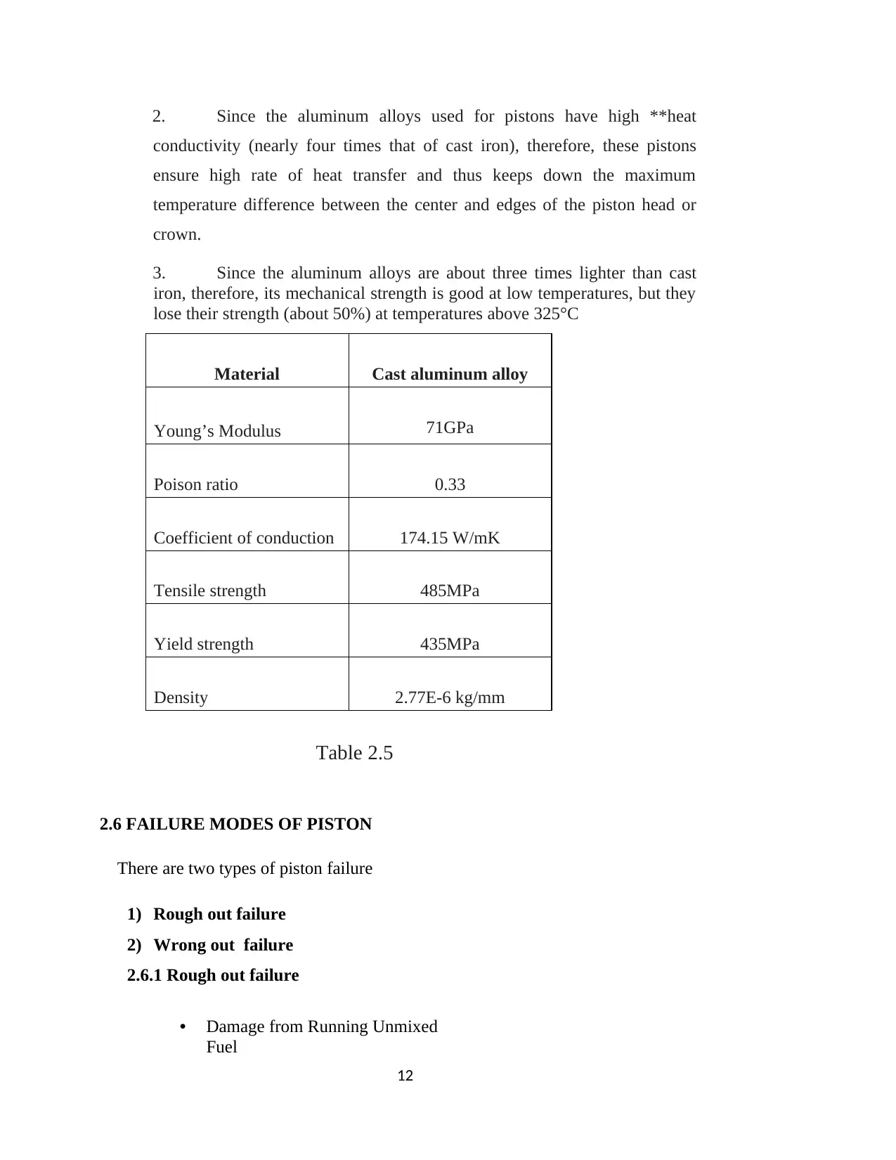
2. Since the aluminum alloys used for pistons have high **heat
conductivity (nearly four times that of cast iron), therefore, these pistons
ensure high rate of heat transfer and thus keeps down the maximum
temperature difference between the center and edges of the piston head or
crown.
3. Since the aluminum alloys are about three times lighter than cast
iron, therefore, its mechanical strength is good at low temperatures, but they
lose their strength (about 50%) at temperatures above 325°C
Material Cast aluminum alloy
Young’s Modulus 71GPa
Poison ratio 0.33
Coefficient of conduction 174.15 W/mK
Tensile strength 485MPa
Yield strength 435MPa
Density 2.77E-6 kg/mm
Table 2.5
2.6 FAILURE MODES OF PISTON
There are two types of piston failure
1) Rough out failure
2) Wrong out failure
2.6.1 Rough out failure
• Damage from Running Unmixed
Fuel
12
⊘ This is a preview!⊘
Do you want full access?
Subscribe today to unlock all pages.
Trusted by 1+ million students worldwide
1 out of 23

Your All-in-One AI-Powered Toolkit for Academic Success.
+13062052269
info@desklib.com
Available 24*7 on WhatsApp / Email
![[object Object]](/_next/static/media/star-bottom.7253800d.svg)
Unlock your academic potential
Copyright © 2020–2025 A2Z Services. All Rights Reserved. Developed and managed by ZUCOL.