Design and Analysis of Sea Wave Induced Energy Generator
VerifiedAdded on 2022/11/15
|48
|8058
|194
AI Summary
This thesis explores the design of a permanent magnet linear generator which is meant for the conversion of wave energy to electrical energy. It adopts a mathematical model approach which helps in analysis of the PLMG performance with respect to the changes of the ocean waves, as well as its output characteristics.
Contribute Materials
Your contribution can guide someone’s learning journey. Share your
documents today.
Design And Analysis Of Sea Wave Induced Energy Generator 1
DESIGN ANALYSIS OF A SEA WAVE INDUCED ENERGY GENERATOR
Name of student
Course
Instructor
Institution filiation
Location
Date
DESIGN ANALYSIS OF A SEA WAVE INDUCED ENERGY GENERATOR
Name of student
Course
Instructor
Institution filiation
Location
Date
Secure Best Marks with AI Grader
Need help grading? Try our AI Grader for instant feedback on your assignments.
Design And Analysis Of Sea Wave Induced Energy Generator 2
ABSTRACT
Currently, several technologies have been designed aimed at sustainably producing
energy. However, the mode of harnessing energy or storage is associated with a variety of
limitations. This has resulted in a technological gap which would have otherwise facilitated more
designs to advance the energy generation spectre. Research has highlighted a more advanced and
robust approach, utilizing a permanent magnet linear generator. Generation of electrical energy
from the oceanic wave is dependent on the behaviour of the ocean, as well as the dynamics of the
wave. This thesis has explored the design of a permanent magnet linear generator which is meant
for the conversion of wave energy to electrical energy. It has adopted a mathematical model
approach which helps in analysis of the PLMG performance with respect to the changes of the
ocean waves, as well as its output characteristics.
In terms of the various wave conditions; the current generated, generated power/voltage,
the applied force, as well as the magnetic flux linkage of the PMLG in reference to the sea wave
conditions, is represented. Simulation of the proposed PMLG has been enabled by the use of a
software package known as ANSYS/ANSOFT. The transient analysis, however, has been
achieved through variation of different factors with time. These factors include flux density, flux
lines, field intensity of the PLMG that has been suggested.

Design And Analysis Of Sea Wave Induced Energy Generator 3
ACKNOWLEDGEMENTS
I would begin by thanking my tutor for guiding me through the thesis project, even at times that
he was off duty. Your door was always open whenever I needed any assistance
Also, I would like to extend my gratitude to the librarian who allowed me to use the library
facilities as well as the research resources at any given time
My parents as well have helped me, encouraging me daily to keep steering above, their efforts
also cannot go unnoticed
Finally, I owe everything unto the almighty who has guided me through the project offering me
protection and guidance all through
Author
Design And Analysis Of Sea Wave Induced Energy Generator 4
TABLE OF CONTENTS
ACKNOWLEDGEMENTS.............................................................................................................3
1. INTRODUCTION....................................................................................................................8
1.1 Aim.........................................................................................................................................9
1.2 Objectives...............................................................................................................................9
1.3 Background of the study........................................................................................................9
1.4 Significance of the study......................................................................................................10
2. LITERATURE REVIEW.......................................................................................................11
2.1 Wave Energy........................................................................................................................12
2.2 Design of PMLG..................................................................................................................13
2.3 Wave Equation.....................................................................................................................14
2.4 Disadvantage of Wave energy.............................................................................................14
2.5 Potentiality...........................................................................................................................15
3. METHODOLOGY.................................................................................................................26
3.1 Principle of the PMLG.........................................................................................................26
3.2 Development of PMLG........................................................................................................26
3.3 Selection of vector diagram and circuit...............................................................................27
4. PRELIMINARY RESULTS......................................................................................................29
5. SUMMARY AND RESEARCH PLAN....................................................................................39
4.1 Future scope.........................................................................................................................39
4.2 Limitation.............................................................................................................................40
4.3 Recommendation.................................................................................................................41
4.3.1 Recommendation 1: Stimulation of investment in innovation......................................41
4.3.2 Recommendation 2: Improvement of cooperation and coordination............................42
4.3.3 Recommendation 3: Implementing technologies for risk assessment...........................43
REFERENCES..............................................................................................................................45
Secure Best Marks with AI Grader
Need help grading? Try our AI Grader for instant feedback on your assignments.
Design And Analysis Of Sea Wave Induced Energy Generator 5
List of figures
Figure 1: Position of the translator for time. t1.............................................................................15
Figure 3: Vector Diagram..............................................................................................................16
Figure 4: resulting diagram of PMLG...........................................................................................17
Figure 5: PMLG construction........................................................................................................18
Figure 6: Position of Translator at Different Time........................................................................20
Figure 7: Pole Pitch of Stator and Translator................................................................................22
Figure 8: direction of various forces..............................................................................................22
Figure 9: Translator position in PMLG.........................................................................................26
Figure 10: Current and Voltage Waveforms.................................................................................28
Figure 11: PLMG Forces...............................................................................................................29
Figure 12: Induced Current, Voltage, And Flux Linkage..............................................................30
Figure 13: Generated Power.........................................................................................................30
Figure 14: Terminal Voltage for Different Loads.........................................................................31
Figure 15: Load Currents...............................................................................................................32
Figure 16: Generated Power..........................................................................................................33
Figure 17: Translator Position And Velocity.................................................................................33
Figure 18: Generated Voltage........................................................................................................34
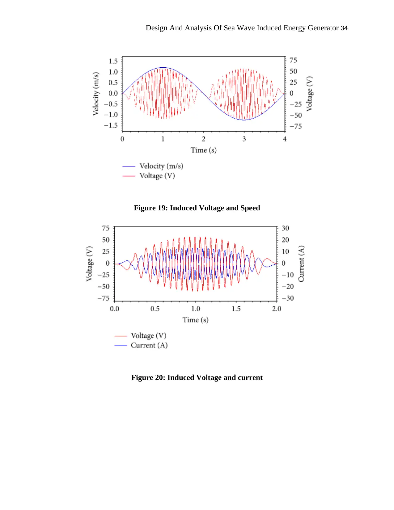
Figure 19: Induced Voltage and Speed..........................................................................................34
Figure 20: Induced Voltage and current........................................................................................34
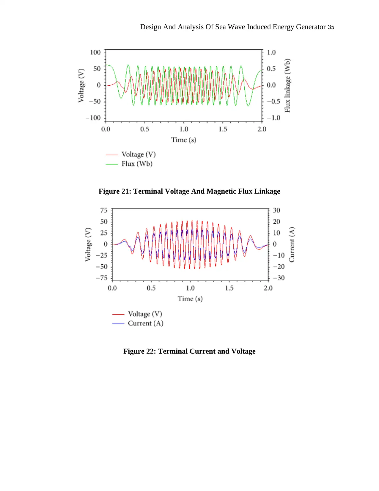
Figure 21: Terminal Voltage And Magnetic Flux Linkage...........................................................35
Figure 22: Terminal Current and Voltage.....................................................................................36
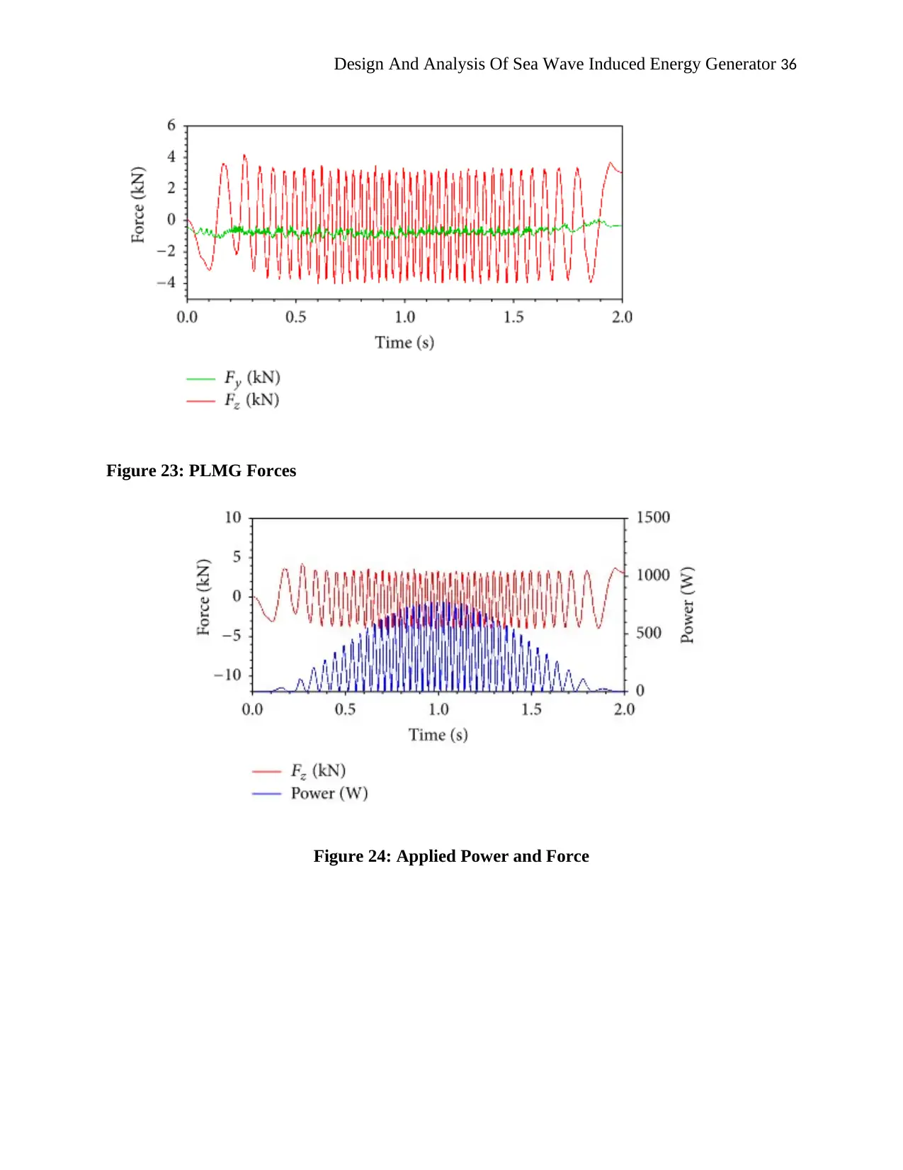
Figure 23: PLMG Forces...............................................................................................................36
Figure 24: Applied Power and Force.............................................................................................37

Design And Analysis Of Sea Wave Induced Energy Generator 6
List of tables
Table 1: Obtained PMLG Values of fig 15...................................................................................31
Table 2: Obtained PMLG Values of fig 16...................................................................................32
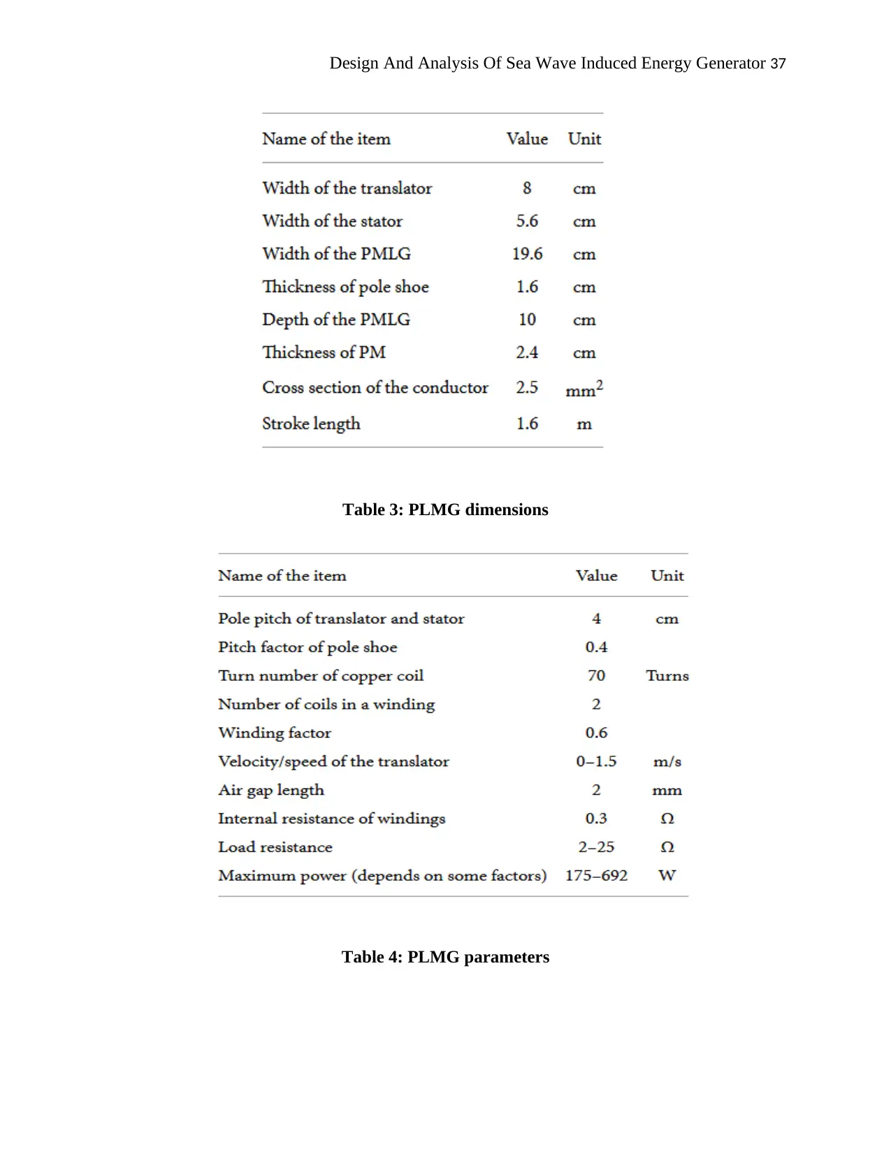
Table 3: PLMG dimensions...........................................................................................................37
Table 4: PLMG parameters...........................................................................................................38
Design And Analysis Of Sea Wave Induced Energy Generator 7
1.0 INTRODUCTION
Wave energy is also known as ocean wave energy that is considered as best source of
renewable energy by utilising the potential of the waves to produce electricity. It is an oscillating
low-frequency source that has the potential to convert 60 HZ frequency into electricity through
placing equipment on the ocean. The purpose of the study is to analyse the design of a sea wave
induced generator that helps in understanding a legitimate way to produce electricity with the
help of ocean wave energy. In order to explore wide aspects of ocean waves energy, a linear
generator has been used those facilitates in seeking the full potential of sea wave positively. The
report sheds light on the working principle of induced generate to produce electricity so that a
positive change can be amending positively (Akpınar & Kömürcü., 2013).
1.1 Aim
The aim of this report is to examine the design of a sea wave induced generator to
generate large amount of electricity along with its working principles.
1.2 Objectives
To examine the design of a sea wave induce generator so that maximum potential energy can
be generated
To analysis current issues and challenges liner generator
To understand the limitations of a sea wave induced energy generator
To recommend the most effective and reliable way to generate a large amount of electricity
positively
Paraphrase This Document
Need a fresh take? Get an instant paraphrase of this document with our AI Paraphraser
Design And Analysis Of Sea Wave Induced Energy Generator 8
1.3 Background of the study
The design of sea wave induced generator has been using to assure that maximum
electricity can be produced by placing generators on the surface of the ocean. It is mostly used in
desalination plants, water pump and power plants. The output energy can be determined through
wave speed, wave height and wave density. In Australia, wave Atlas is one of the major projects
that can be accessible by the public so that all associated stakeholders can be benefited that
embraces project developer, regulator and investors. It contributes up to 11% of Australia energy
that is more than enough to power the city of Melbourne by 2050 (Alberdi et al., 2012).
The Australian we energy Atlas has bled by CSIRO Atmospheres and oceans that provide
a 4D interactive wave of the greater Australia a coastal area relative to a coastal area. In addition,
there are several waves of power devices such as shoreline devices, near shore devices and
offshore devices. It is renewables source of energy that facilitates in creating less impact on the
environment by continually providing the source of energy effectively. The advantage of using
wave energy is that it reduces dependency on fossil fuel that upsurges its reliability and
suitability (Altomare et al., 2015). On the contrary, the major disadvantage of the wave energy is
high power distribution costs to send the generated power through using offshore devices. An
average 10-second and 4 foot wave striking ocean generates more than 3500 horsepower per
mile of the coast. In this report, a linear generator has been used that facilitates in extracting
maximum power of ocean wave energy without creating any adverse effect on the environment.
The permanent magnet linear generator (PMLG) is one of the effective designs for generating
maximum electric power (Antonio., 2010).
The translator moves vertically with an incident wave that is upward and downward by
using permanent magnet This PMLG model of sea wave induced wave generator help in

Design And Analysis Of Sea Wave Induced Energy Generator 9
converting maximum potential electricity without creating an adverse effect on the environment.
One of the major challenges in this model of design is the utilization of high power magnet that
has been encounter through aligning a range of magnet in a sequence to make sure maximum
potential energy can be produced positively (Astariz & Iglesias., 2015).
1.4 Significance of the study
The report has enlightened the major role and responsibility of ocean wave energy in
generating electricity, which is a renewable source of energy that helps in producing supplying
continuous supply of electricity. This report supports several energy producing organizations to
change its approach to induced energy generator so that maximum power or energy can be
extracted. The main advantage of wave energy is that the source is not limited and producing
electricity from the wave energy in environmentally safe and does not create any pollution.
Design And Analysis Of Sea Wave Induced Energy Generator 10
2. LITERATURE REVIEW
In present days our world is facing two big challenges one is a shortage of energy due to
an increase in global population and another one is pollution. These two are threatening the
world and two major concerns in our world. Day by day increase in the global population
increasing the power demand and to sustain exponential growth of any civilization power
demand has to be met. Due to the increase of power demand governments, countries trying to
produce as much energy to meet the increasing demand (Titah-Benbouzid and Benbouzid, 2014).
The main source of energy produced globally is fossil fuel. Fossil fuel is a non-renewable energy
source and combustion of fossil fuel produces different harmful gases like Carbon dioxide,
Carbon Monoxide, Methane etc. Due to excess release of these harmful gases in the environment
the pollution has been increased the level day by day. As the source of fossil fuel is also limited
in our environment it cannot fulfil the demand of energy in upcoming days (Gonçalves and
Martinho, 2014). So it has become a major concern for our scientists and they are trying to
produce energy from renewable sources. Our planet, our home is covered by 75% of water and
the main sources are oceans and seas (Beirao & Malça., 2014).
The wave and the current in the oceans are created by the wind possess huge energy
power. Improvement in technology has enabled our scientist and engineers to generate electricity
from the wave. Electricity is produced from ocean energy. It is one of the largest sources of
renewable energy source globally. The main advantage of wave energy is that the source is not
limited and producing electricity from the wave energy in environmentally safe and does not
create any pollution (Soares et al., 2014). Many countries are trying to develop new technologies
to create more electricity from wave energy and many are showing interest to develop. Wave
Secure Best Marks with AI Grader
Need help grading? Try our AI Grader for instant feedback on your assignments.
Design And Analysis Of Sea Wave Induced Energy Generator 11
power is capturing of wind waves for producing electricity to do work and the energy is
converted by a complex machine called wave energy converter (Bento et al., 2014).
Waves are created by many factors wind, temperature, salinity and humidity etc. World
first commercial power device, Wave Power Device the Islay LIMPET is installed in the year
2000 on the coast of Islay in Scotland. The first experimental multi-generator wave farm The
Agucadoura Wave Park is opened in Portugal in 2008 (Parkinson et al., 2015). Wind passing the
surface of the oceans and seas create the wave. The energy is transferred from the wind to the
wave which is then sued to generate electricity. Increase in shear stress causes the growth of the
waves. Wave height depends on various factors the wind speed, the duration of wind, depth and
topography of the seafloor. Larger waves and powerful waves create more energy which
eventually creates more electricity (Bracco et al., 2011).
The first patented use of wave energy is by Girard in 1799 on Paris. An early application
of wave power device is created by Bochaux-Praceique. Modern pursuit of wave energy device
has been created by Yoshio Masuda. The more advanced model has been produced by Stephen
Salter known as Salter's duck in 1974. In 2003 the European Marine Energy Centre is established
in Scotland to develop, research new ideas technology regarding wave energy. When a group of
wave devices are installed is called wave farms. To meet the increasing energy demand this wave
farms are installed. The aim of these wave farms is to get high power production in a limited area
(Cappelli et al., 2013).
2.1 Wave Energy
Wave Power farm Bombora wave power in Perth, Australia creating mWave flexible
wave converter, developing new innovative technologies to produce electricity. Ocean Power
Technologies is creating a 19mW project in Portland, Australia (Bento et al., 2014). CETO Wave
Design And Analysis Of Sea Wave Induced Energy Generator 12
firm is a very large wave farm in Western Australia started operation in 2015. Oceanlinx has
created a wave firm in Port Macdonnel. Not only in Australia but throughout the world many
countries are showing interest in installing wave farm. In Kanohe Bay Oahu Hawaii USA has
started a wave farm project. In Reedsport, Oregon USA a wave farm of 1.5 mW has been
installed. Islay LIPMET has been installed in Australia and connected to the national grid (Chen
et al., 2016).
2.2 Design of PMLG
PMLG can be described as a linear generator that consists of two parts such as translator
and stator. The parameters of the generator are selected in order to achieve maximum energy
output from ocean wave forces. The poles are indicated with the red and green colour that
determines the North and South Pole of the magnet linear generator. The position of poles in
translator is changed according to a specific time interval (Soltanmohamadi and Lakzian, 2016).
It has been identified that the movement of both the translator and stator are determined by the
forces of the ocean wave. It has been stated that translator of PMLG is mounted to a hollow
cylinder. The electrical wave energy has been produced when the movement of a translator is in
a linear direction. The linear direction movement is mainly occurred by the motion of the floater.
The stator is consisted of some copper coil (Chen et al., 2016).
These coils are rounded in both sides of the translator. The hollow cylinder has been
referred to a floater. On the other side, the stator is generally mounted to the mechanical parts of
PMLG. Floaters are used in order to utilise the ocean wave for energy transformations at a single
point (Samrat and Ahmad, Choudhury, 2014). This addition polarity is induced in order to
achieve maximum output voltage. The circuit diagram of the linear generator has been selected
for three-phase load. The resistance and inductances of the individual phase have been
Design And Analysis Of Sea Wave Induced Energy Generator 13
considered in order to get a high output voltage. Each phase of translator contains to coils of
opposite phase. The 180° phase is sifted with induced voltage. On the other side, the coils of
individual phase are associated with addition polarity (Coe & Neary, 2015).
2.3 Wave Equation
Wave power is one of the best sources of energy by utilizing wind waves and
consumption of that energy to produce electricity and do useful work, for example, from running
factories to hospital etc. In modern days everything runs on energy. The capability of machine is
exploiting wave power is known as a wave energy converter. Wave power is different from the
diurnal flux of tidal power and the steady gyre of ocean currents (Chen et al., 2016). On the
whole, wave power is energy transport by the wave surface of the ocean.
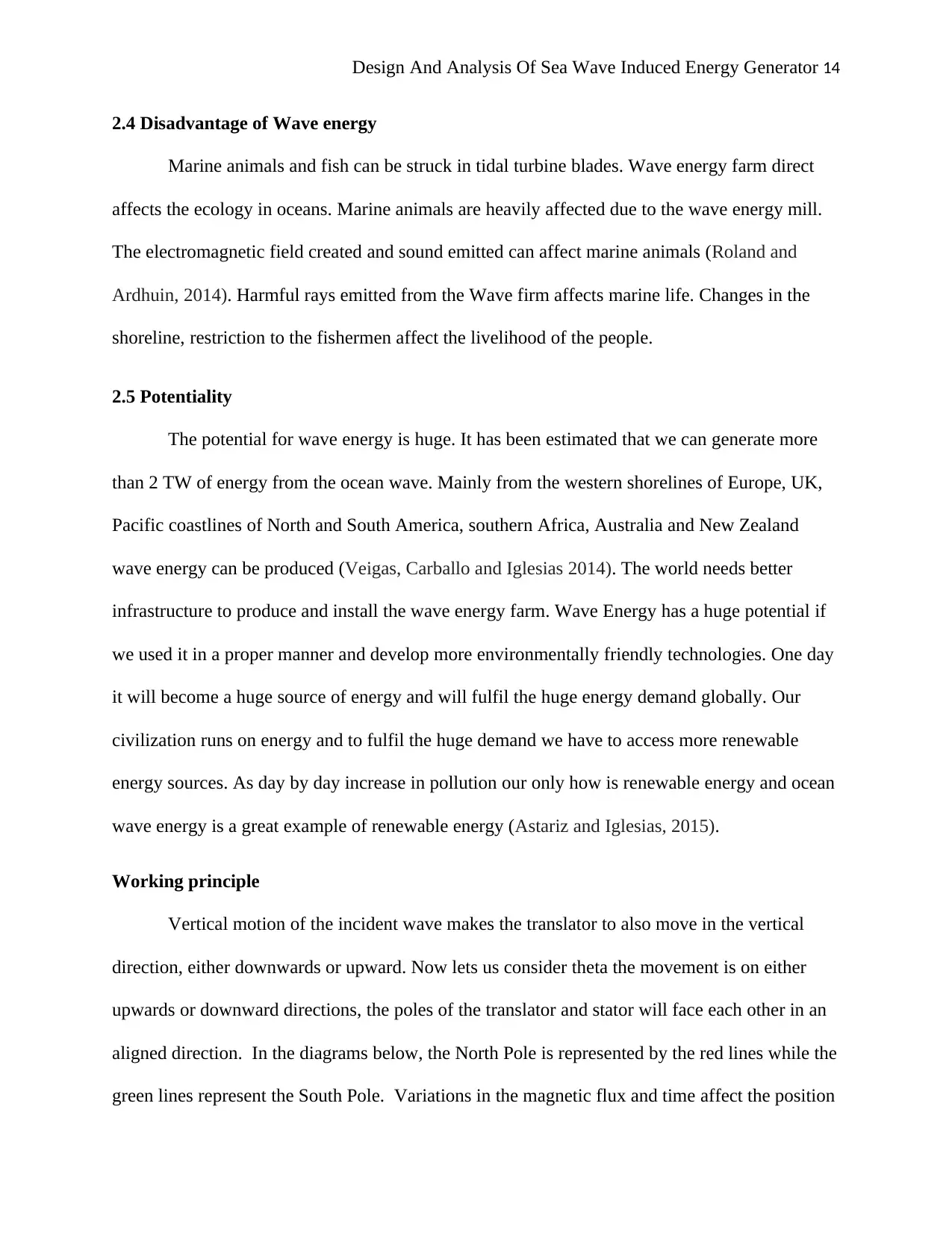
The Wave power formula is given by,
Where,
P = power of water wave present in-depth (Watts),
ρ = water density (1.025 kg/m3),
g = acceleration due to gravity (9.81 m/s2),
T = wave period,
h = Height of wave
l = wave front length.
Paraphrase This Document
Need a fresh take? Get an instant paraphrase of this document with our AI Paraphraser
Design And Analysis Of Sea Wave Induced Energy Generator 14
2.4 Disadvantage of Wave energy
Marine animals and fish can be struck in tidal turbine blades. Wave energy farm direct
affects the ecology in oceans. Marine animals are heavily affected due to the wave energy mill.
The electromagnetic field created and sound emitted can affect marine animals (Roland and
Ardhuin, 2014). Harmful rays emitted from the Wave firm affects marine life. Changes in the
shoreline, restriction to the fishermen affect the livelihood of the people.
2.5 Potentiality
The potential for wave energy is huge. It has been estimated that we can generate more
than 2 TW of energy from the ocean wave. Mainly from the western shorelines of Europe, UK,
Pacific coastlines of North and South America, southern Africa, Australia and New Zealand
wave energy can be produced (Veigas, Carballo and Iglesias 2014). The world needs better
infrastructure to produce and install the wave energy farm. Wave Energy has a huge potential if
we used it in a proper manner and develop more environmentally friendly technologies. One day
it will become a huge source of energy and will fulfil the huge energy demand globally. Our
civilization runs on energy and to fulfil the huge demand we have to access more renewable
energy sources. As day by day increase in pollution our only how is renewable energy and ocean
wave energy is a great example of renewable energy (Astariz and Iglesias, 2015).
Working principle
Vertical motion of the incident wave makes the translator to also move in the vertical
direction, either downwards or upward. Now lets us consider theta the movement is on either
upwards or downward directions, the poles of the translator and stator will face each other in an
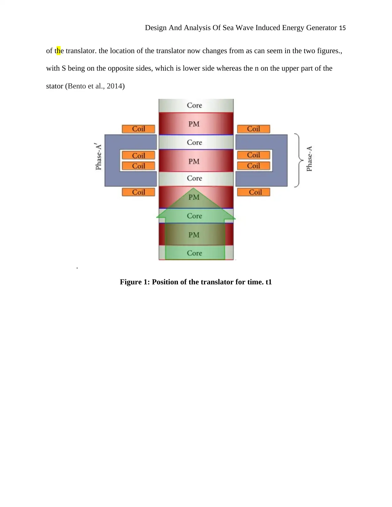
aligned direction. In the diagrams below, the North Pole is represented by the red lines while the
green lines represent the South Pole. Variations in the magnetic flux and time affect the position
Design And Analysis Of Sea Wave Induced Energy Generator 15
of the translator. the location of the translator now changes from as can seem in the two figures.,
with S being on the opposite sides, which is lower side whereas the n on the upper part of the
stator (Bento et al., 2014)
.
Figure 1: Position of the translator for time. t1
of the translator. the location of the translator now changes from as can seem in the two figures.,
with S being on the opposite sides, which is lower side whereas the n on the upper part of the
stator (Bento et al., 2014)
.
Figure 1: Position of the translator for time. t1
Design And Analysis Of Sea Wave Induced Energy Generator 16
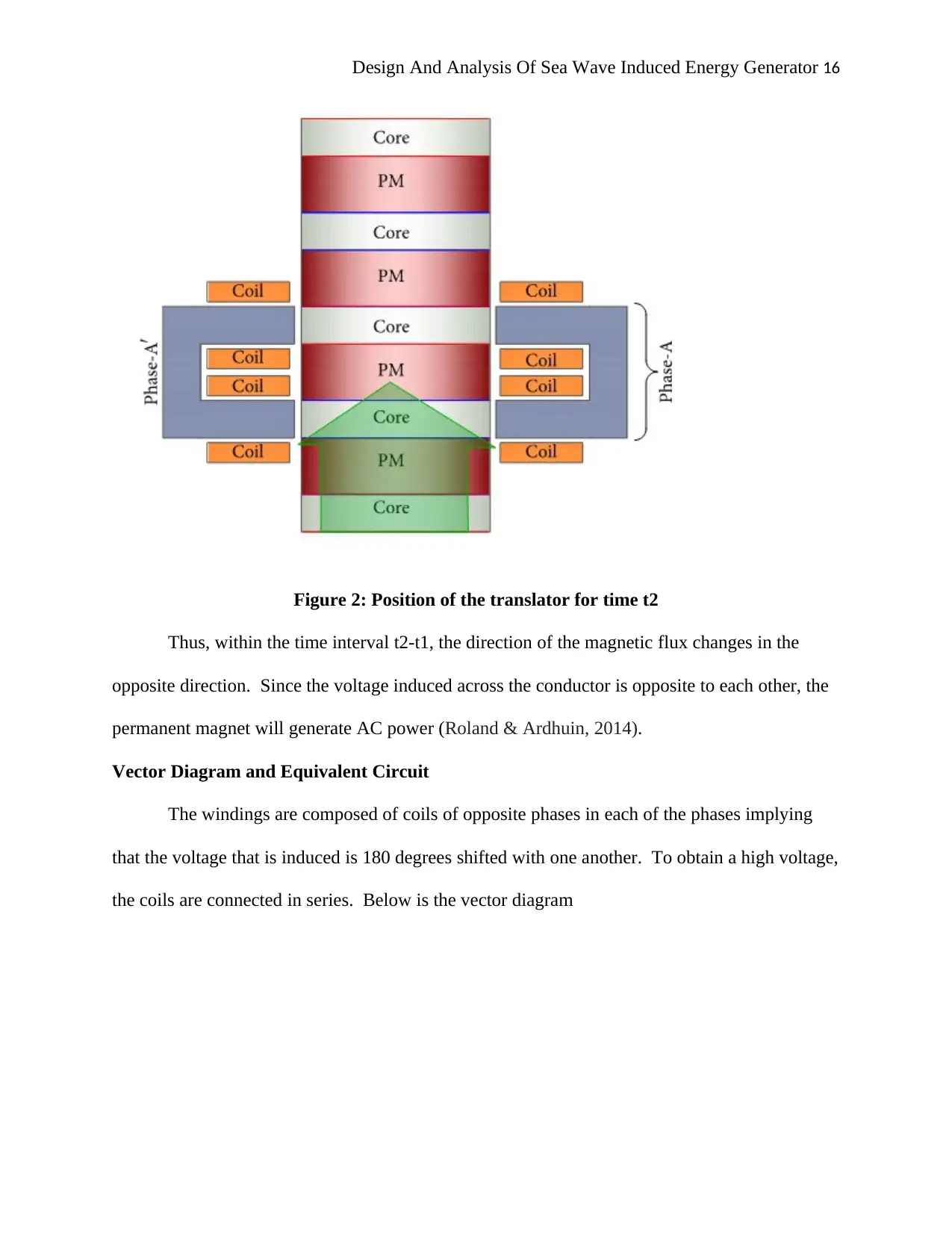
Figure 2: Position of the translator for time t2
Thus, within the time interval t2-t1, the direction of the magnetic flux changes in the
opposite direction. Since the voltage induced across the conductor is opposite to each other, the
permanent magnet will generate AC power (Roland & Ardhuin, 2014).
Vector Diagram and Equivalent Circuit
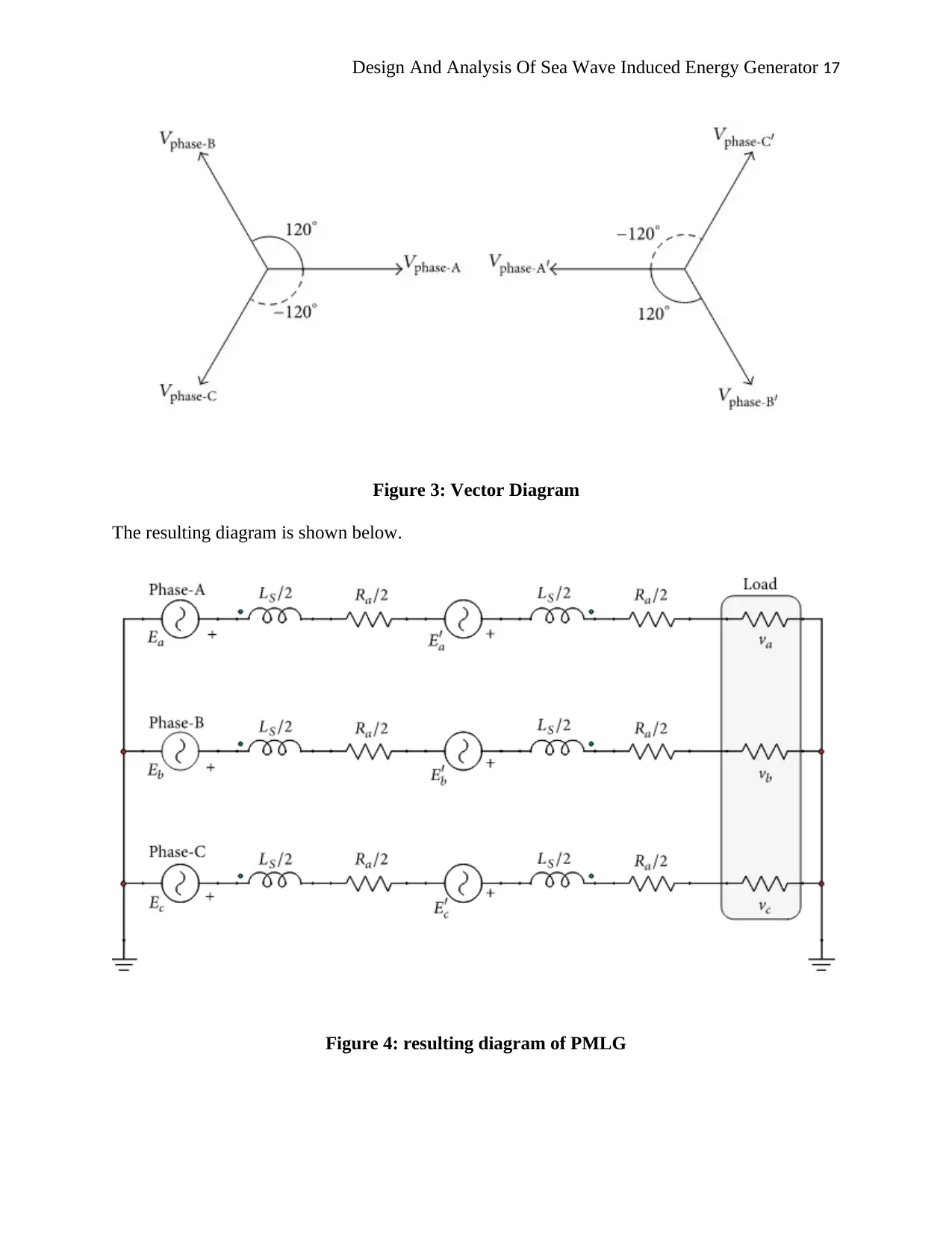
The windings are composed of coils of opposite phases in each of the phases implying
that the voltage that is induced is 180 degrees shifted with one another. To obtain a high voltage,
the coils are connected in series. Below is the vector diagram
Secure Best Marks with AI Grader
Need help grading? Try our AI Grader for instant feedback on your assignments.
Design And Analysis Of Sea Wave Induced Energy Generator 17
Figure 3: Vector Diagram
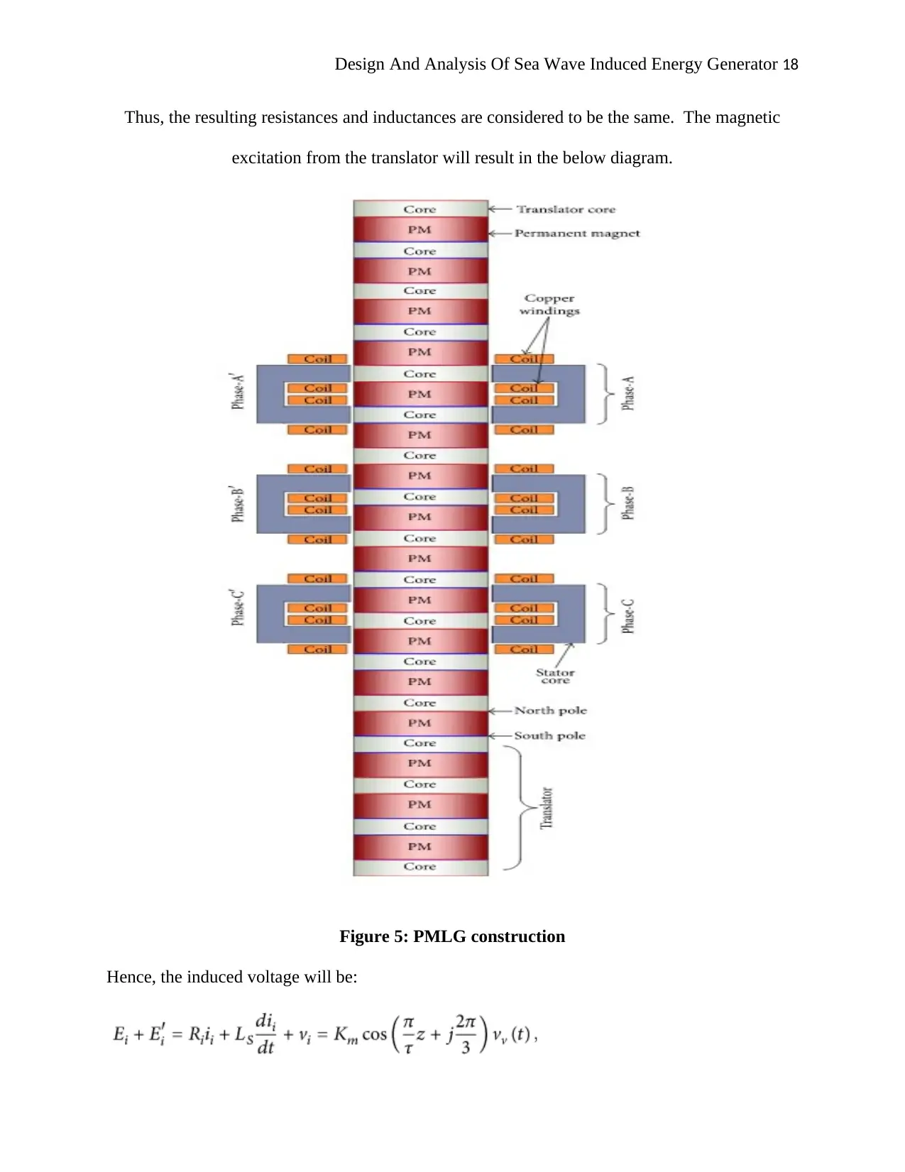
The resulting diagram is shown below.
Figure 4: resulting diagram of PMLG
Figure 3: Vector Diagram
The resulting diagram is shown below.
Figure 4: resulting diagram of PMLG
Design And Analysis Of Sea Wave Induced Energy Generator 18
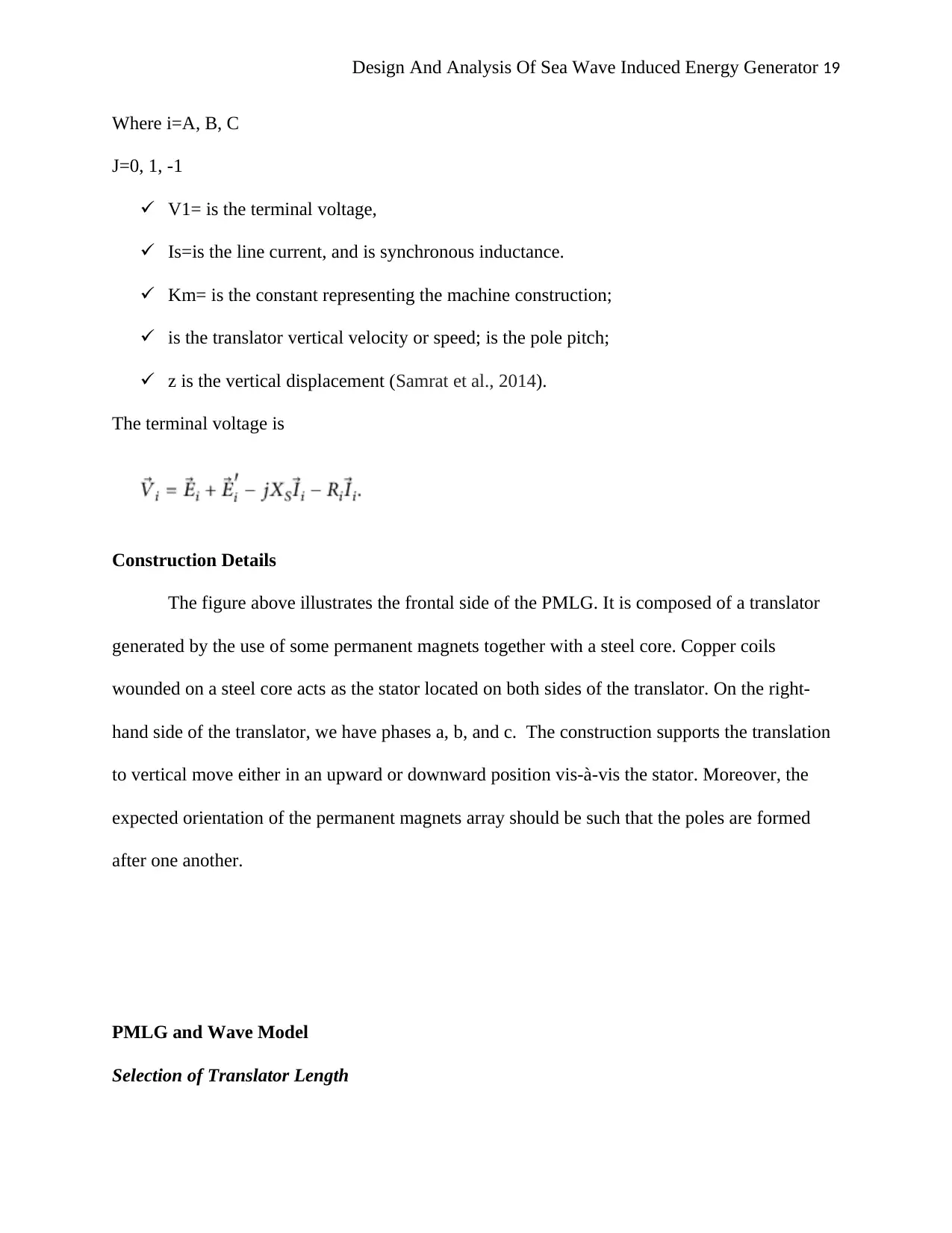
Thus, the resulting resistances and inductances are considered to be the same. The magnetic
excitation from the translator will result in the below diagram.
Figure 5: PMLG construction
Hence, the induced voltage will be:
Thus, the resulting resistances and inductances are considered to be the same. The magnetic
excitation from the translator will result in the below diagram.
Figure 5: PMLG construction
Hence, the induced voltage will be:
Design And Analysis Of Sea Wave Induced Energy Generator 19
Where i=A, B, C
J=0, 1, -1
V1= is the terminal voltage,
Is=is the line current, and is synchronous inductance.
Km= is the constant representing the machine construction;
is the translator vertical velocity or speed; is the pole pitch;
z is the vertical displacement (Samrat et al., 2014).
The terminal voltage is
Construction Details
The figure above illustrates the frontal side of the PMLG. It is composed of a translator
generated by the use of some permanent magnets together with a steel core. Copper coils
wounded on a steel core acts as the stator located on both sides of the translator. On the right-
hand side of the translator, we have phases a, b, and c. The construction supports the translation
to vertical move either in an upward or downward position vis-à-vis the stator. Moreover, the
expected orientation of the permanent magnets array should be such that the poles are formed
after one another.
PMLG and Wave Model
Selection of Translator Length
Paraphrase This Document
Need a fresh take? Get an instant paraphrase of this document with our AI Paraphraser
Design And Analysis Of Sea Wave Induced Energy Generator 20
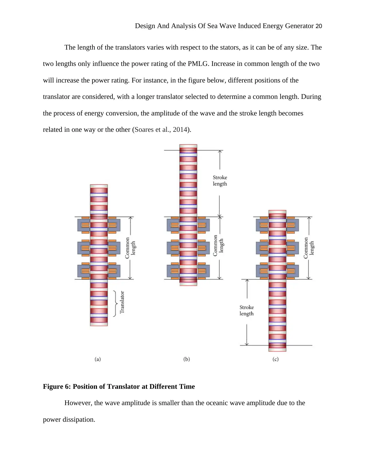
The length of the translators varies with respect to the stators, as it can be of any size. The
two lengths only influence the power rating of the PMLG. Increase in common length of the two
will increase the power rating. For instance, in the figure below, different positions of the
translator are considered, with a longer translator selected to determine a common length. During
the process of energy conversion, the amplitude of the wave and the stroke length becomes
related in one way or the other (Soares et al., 2014).
Figure 6: Position of Translator at Different Time
However, the wave amplitude is smaller than the oceanic wave amplitude due to the
power dissipation.
Design And Analysis Of Sea Wave Induced Energy Generator 21
Determination of Frequency
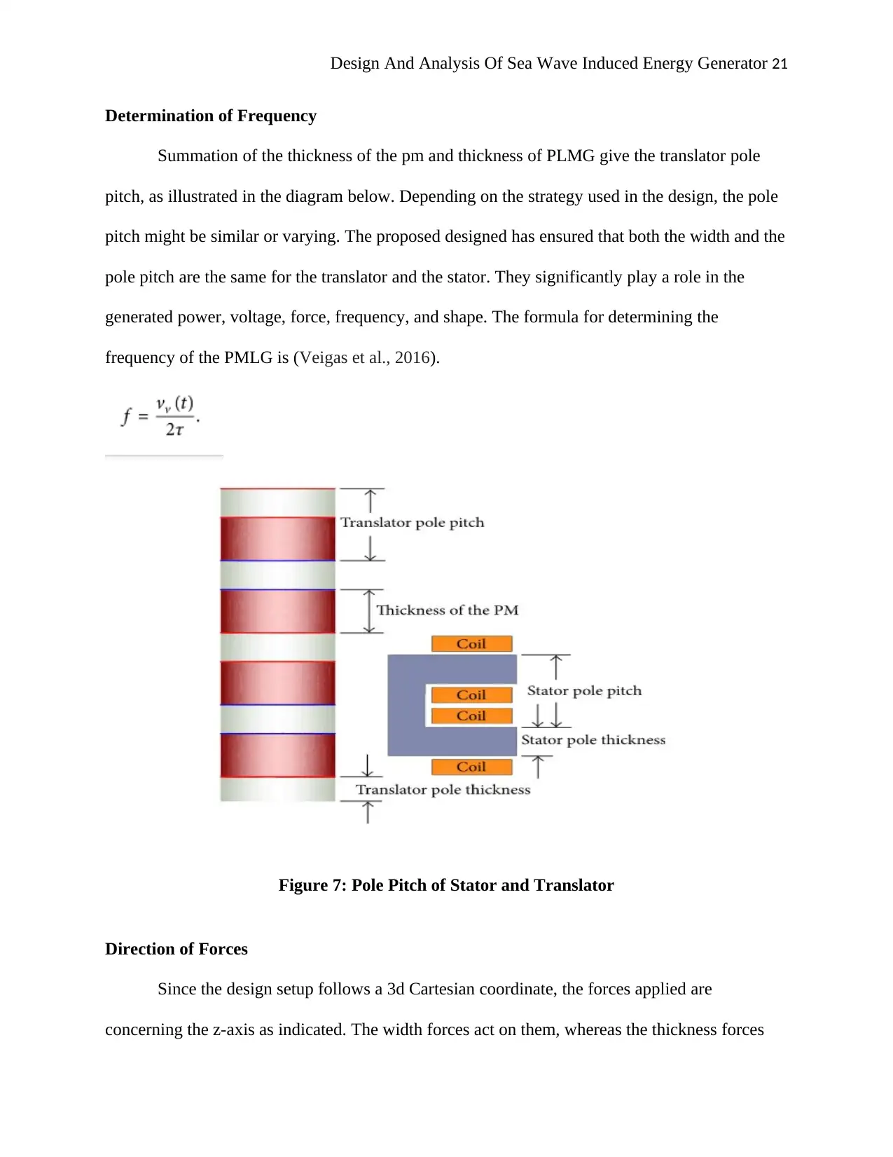
Summation of the thickness of the pm and thickness of PLMG give the translator pole
pitch, as illustrated in the diagram below. Depending on the strategy used in the design, the pole
pitch might be similar or varying. The proposed designed has ensured that both the width and the
pole pitch are the same for the translator and the stator. They significantly play a role in the
generated power, voltage, force, frequency, and shape. The formula for determining the
frequency of the PMLG is (Veigas et al., 2016).
Figure 7: Pole Pitch of Stator and Translator
Direction of Forces
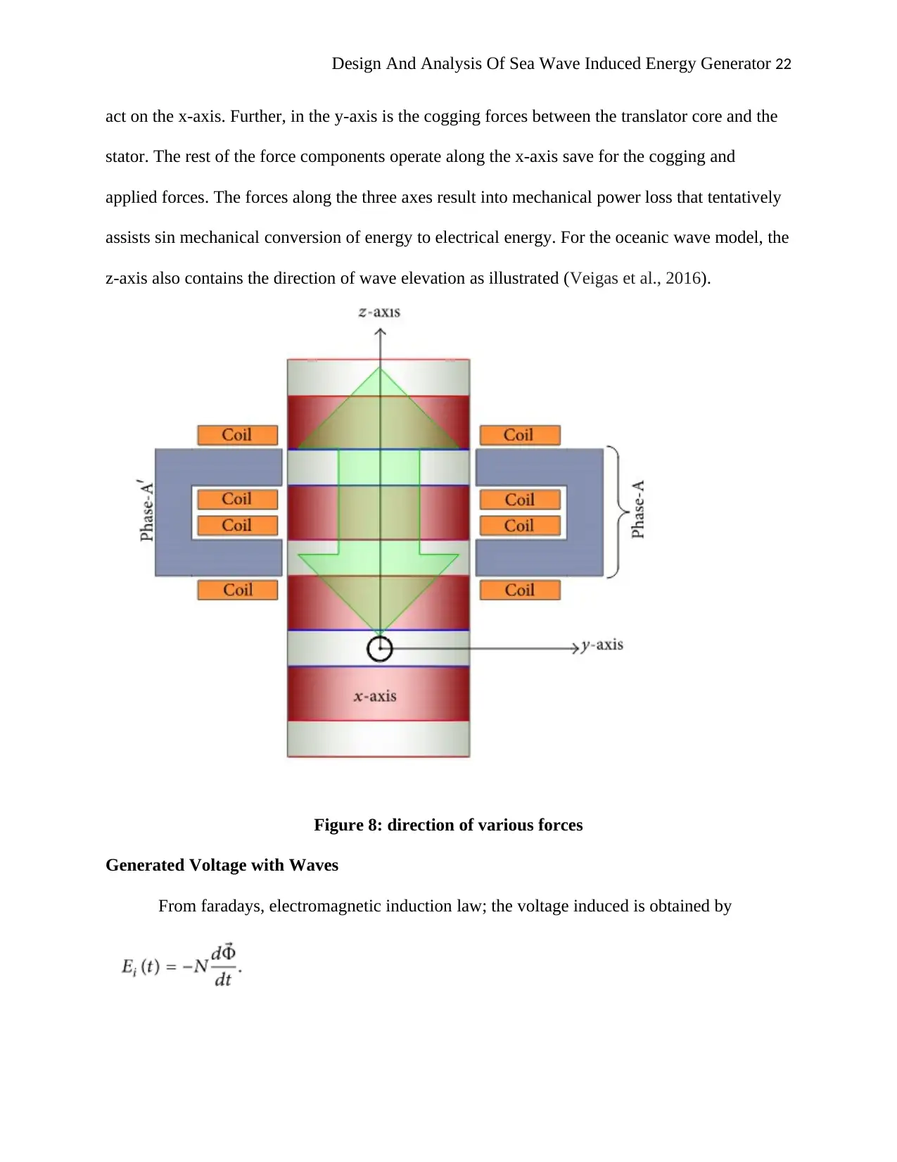
Since the design setup follows a 3d Cartesian coordinate, the forces applied are
concerning the z-axis as indicated. The width forces act on them, whereas the thickness forces
Design And Analysis Of Sea Wave Induced Energy Generator 22
act on the x-axis. Further, in the y-axis is the cogging forces between the translator core and the
stator. The rest of the force components operate along the x-axis save for the cogging and
applied forces. The forces along the three axes result into mechanical power loss that tentatively
assists sin mechanical conversion of energy to electrical energy. For the oceanic wave model, the
z-axis also contains the direction of wave elevation as illustrated (Veigas et al., 2016).
Figure 8: direction of various forces
Generated Voltage with Waves
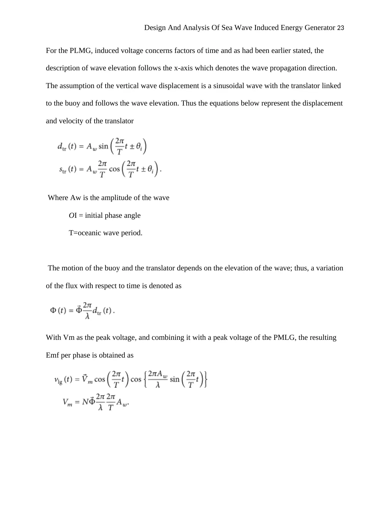
From faradays, electromagnetic induction law; the voltage induced is obtained by
Secure Best Marks with AI Grader
Need help grading? Try our AI Grader for instant feedback on your assignments.
Design And Analysis Of Sea Wave Induced Energy Generator 23
For the PLMG, induced voltage concerns factors of time and as had been earlier stated, the
description of wave elevation follows the x-axis which denotes the wave propagation direction.
The assumption of the vertical wave displacement is a sinusoidal wave with the translator linked
to the buoy and follows the wave elevation. Thus the equations below represent the displacement
and velocity of the translator
Where Aw is the amplitude of the wave
OI = initial phase angle
T=oceanic wave period.
The motion of the buoy and the translator depends on the elevation of the wave; thus, a variation
of the flux with respect to time is denoted as
With Vm as the peak voltage, and combining it with a peak voltage of the PMLG, the resulting
Emf per phase is obtained as

Design And Analysis Of Sea Wave Induced Energy Generator 24
Design And Analysis Of Sea Wave Induced Energy Generator 25
3. METHODOLOGY
In this project, we have mainly focused on the produced energy from an ocean wave. The
project is mainly based on the conversion of energy from wave forces. In this case, we have used
a linear generator in order to get maximum efficiency of energy. We have also used wave energy
converters in order to transform the mechanical energy into electrical energy. The design of a
generator is based on a permanent magnet linear generator (PMLG). The parameters of the
generator are selected in order to achieve maximum energy output from ocean wave forces. The
name of this current project has been CETO 5, which has been started in Western Australia.
3.1 Principle of the PMLG
PMLG has consisted of two main parts that are the translator and stator. The movement
of a translator is vertical. In this case, the direction of PMLG can be upward or downward. The
poles of translator and stator are aligned with facing each other. The poles are indicated with the
red and green colour that determines the North and South Pole of the magnet linear generator.
The position of poles in translator is changed according to a specific time interval. It has been
identified that the movement of both the translator and stator are determined by the forces of the
ocean wave.
3.2 Development of PMLG
PMLG mainly contains two major parts that are translator mad stator. It has been stated
that the translator of PMLG is mounted to a hollow cylinder. The hollow cylinder has been
referred to a floater. On the other side, the stator is generally mounted to the mechanical parts of
PMLG. Floaters are used in order to utilise the ocean wave for energy transformations at a single
point. The electrical wave energy has been produced when the movement of a translator is in a
Paraphrase This Document
Need a fresh take? Get an instant paraphrase of this document with our AI Paraphraser
Design And Analysis Of Sea Wave Induced Energy Generator 26
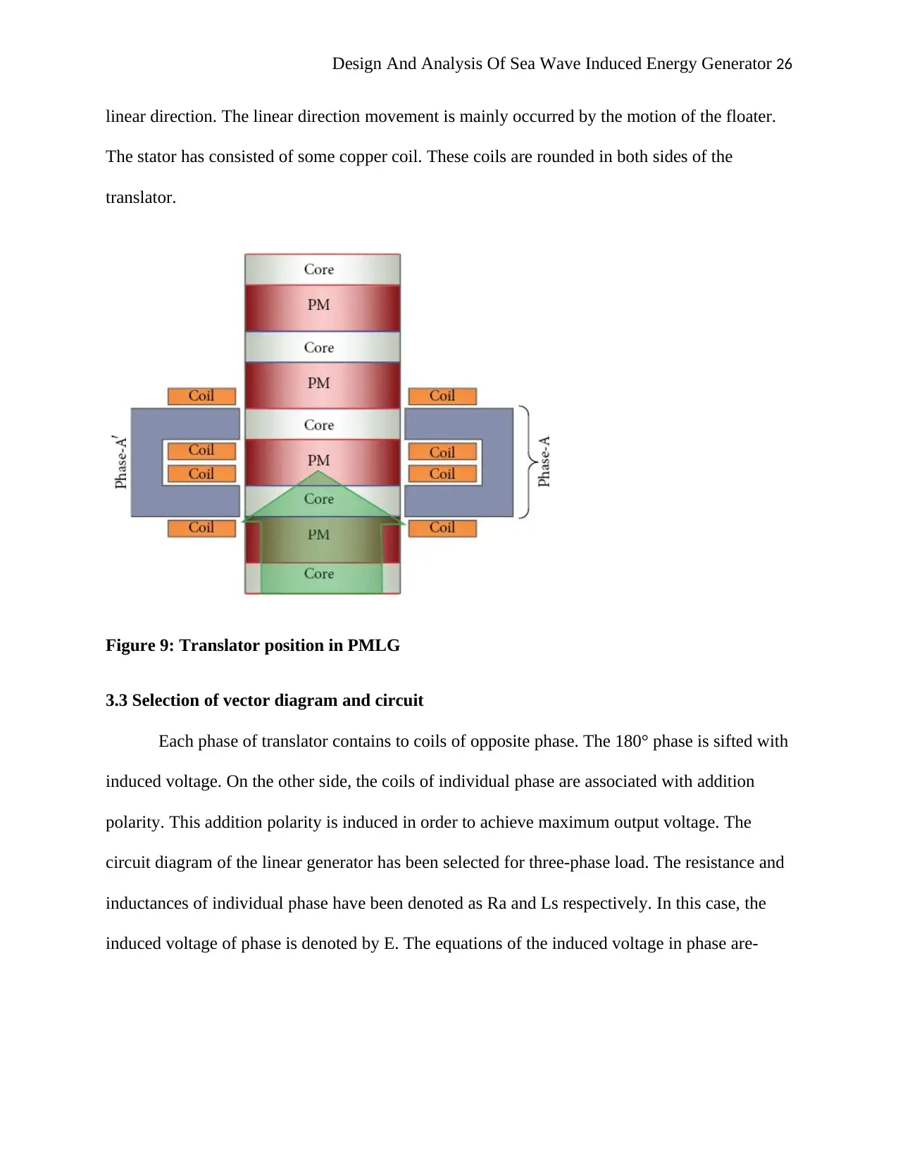
linear direction. The linear direction movement is mainly occurred by the motion of the floater.
The stator has consisted of some copper coil. These coils are rounded in both sides of the
translator.
Figure 9: Translator position in PMLG
3.3 Selection of vector diagram and circuit
Each phase of translator contains to coils of opposite phase. The 180° phase is sifted with
induced voltage. On the other side, the coils of individual phase are associated with addition
polarity. This addition polarity is induced in order to achieve maximum output voltage. The
circuit diagram of the linear generator has been selected for three-phase load. The resistance and
inductances of individual phase have been denoted as Ra and Ls respectively. In this case, the
induced voltage of phase is denoted by E. The equations of the induced voltage in phase are-

Design And Analysis Of Sea Wave Induced Energy Generator 27
Design And Analysis Of Sea Wave Induced Energy Generator 28
4.0 PRELIMINARY RESULTS
The simulation has adopted two types of speed settings, constant speed of the translator
for purposes of determining the performance of the PMLG, and variation of the translatory
motion in regards to the incident sea wave. Some of the default values include the air gap length
of 2mm, translator speed of 1m/s, load as 4 Ω unless specified.
Constant Translator Speed
Figure 10: Current and Voltage Waveforms
The resistive load results into the phase current and phase voltage being in equal, and
resulting in the figure below.
Secure Best Marks with AI Grader
Need help grading? Try our AI Grader for instant feedback on your assignments.
Design And Analysis Of Sea Wave Induced Energy Generator 29
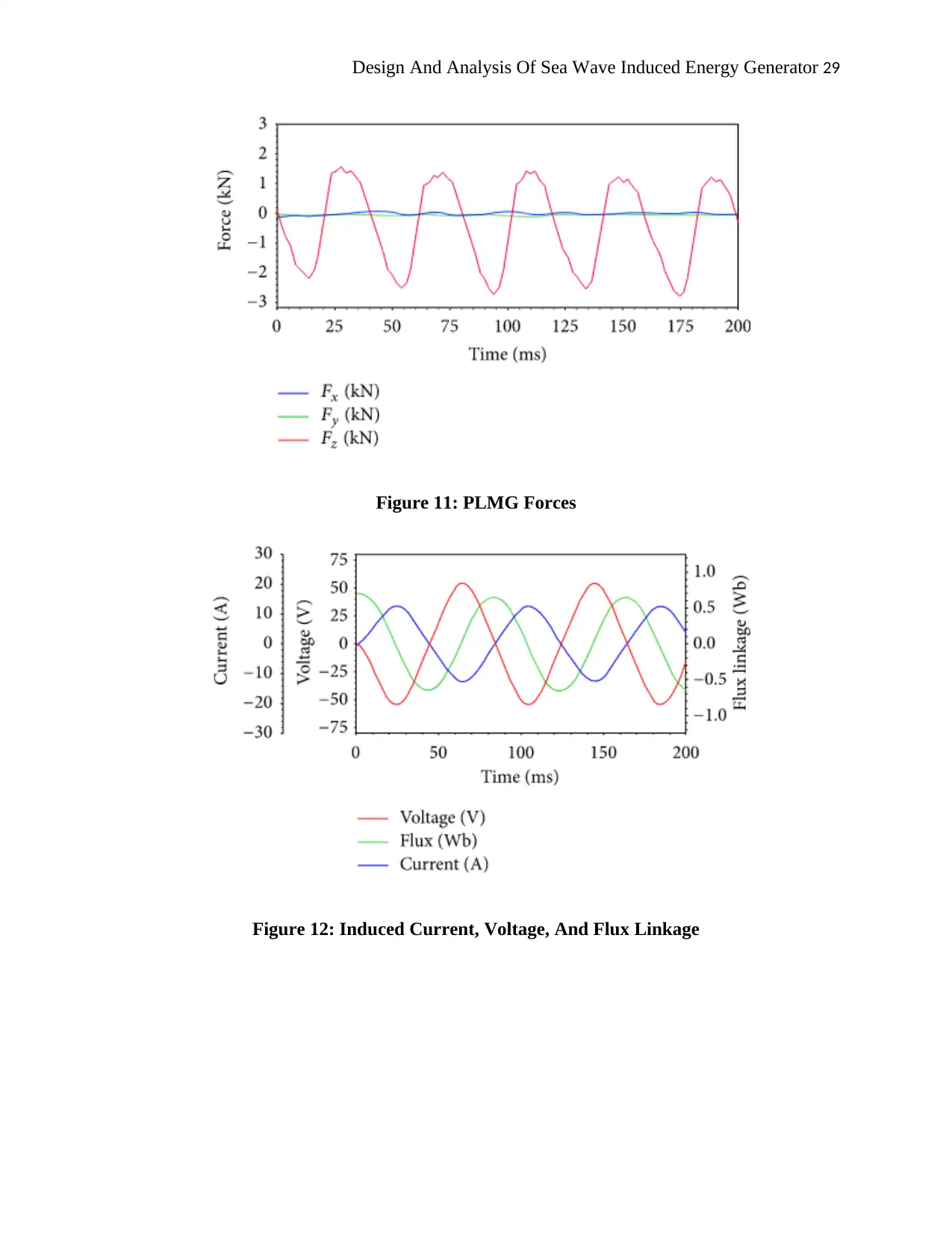
Figure 11: PLMG Forces
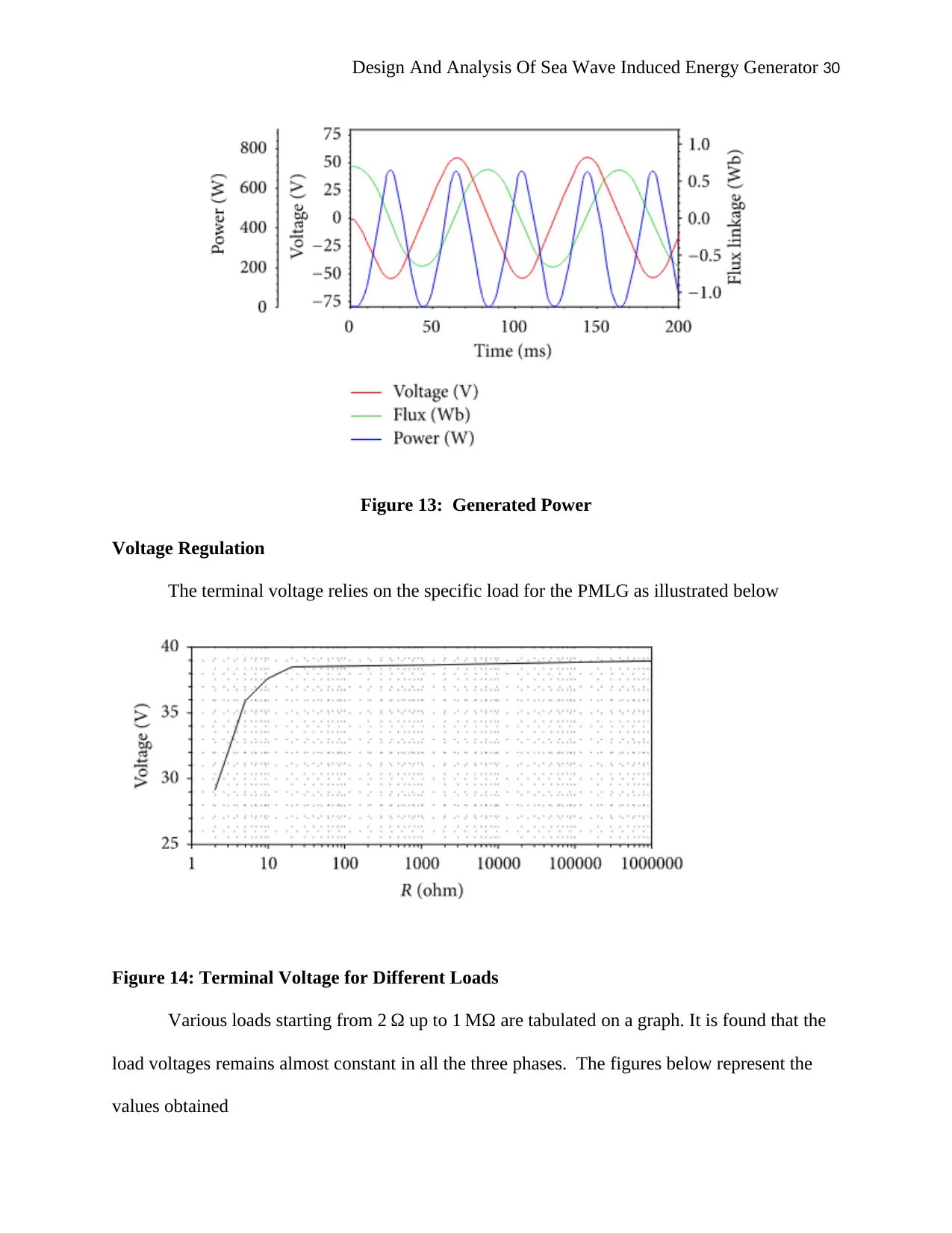
Figure 12: Induced Current, Voltage, And Flux Linkage
Figure 11: PLMG Forces
Figure 12: Induced Current, Voltage, And Flux Linkage
Design And Analysis Of Sea Wave Induced Energy Generator 30
Figure 13: Generated Power
Voltage Regulation
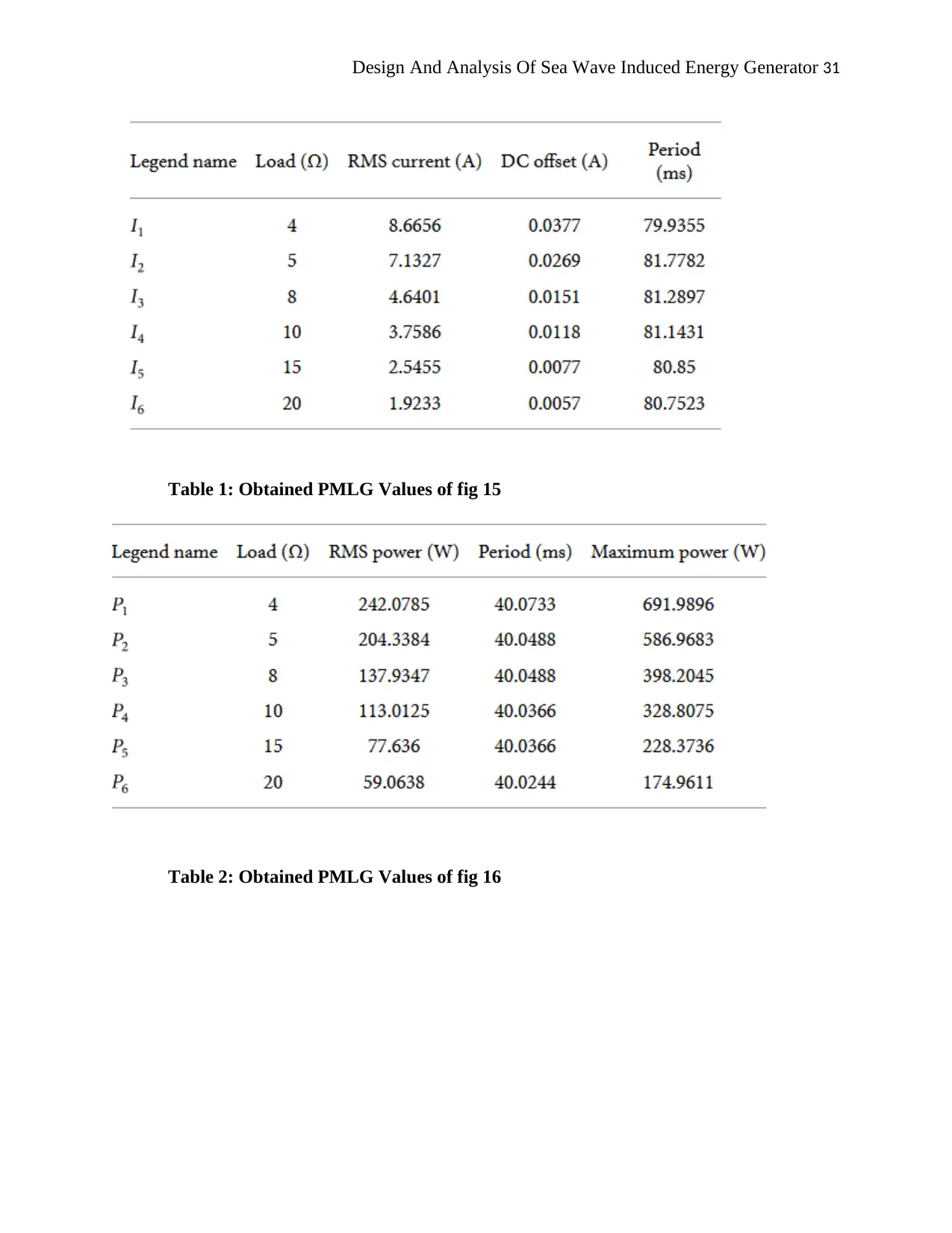
The terminal voltage relies on the specific load for the PMLG as illustrated below
Figure 14: Terminal Voltage for Different Loads
Various loads starting from 2 Ω up to 1 MΩ are tabulated on a graph. It is found that the
load voltages remains almost constant in all the three phases. The figures below represent the
values obtained
Design And Analysis Of Sea Wave Induced Energy Generator 31
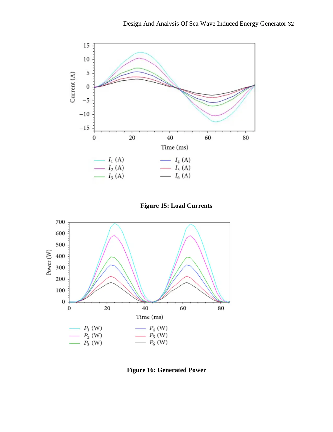
Table 1: Obtained PMLG Values of fig 15
Table 2: Obtained PMLG Values of fig 16
Table 1: Obtained PMLG Values of fig 15
Table 2: Obtained PMLG Values of fig 16
Paraphrase This Document
Need a fresh take? Get an instant paraphrase of this document with our AI Paraphraser
Design And Analysis Of Sea Wave Induced Energy Generator 32
Figure 15: Load Currents
Figure 16: Generated Power
Figure 15: Load Currents
Figure 16: Generated Power
Design And Analysis Of Sea Wave Induced Energy Generator 33
Variable Translator Speed
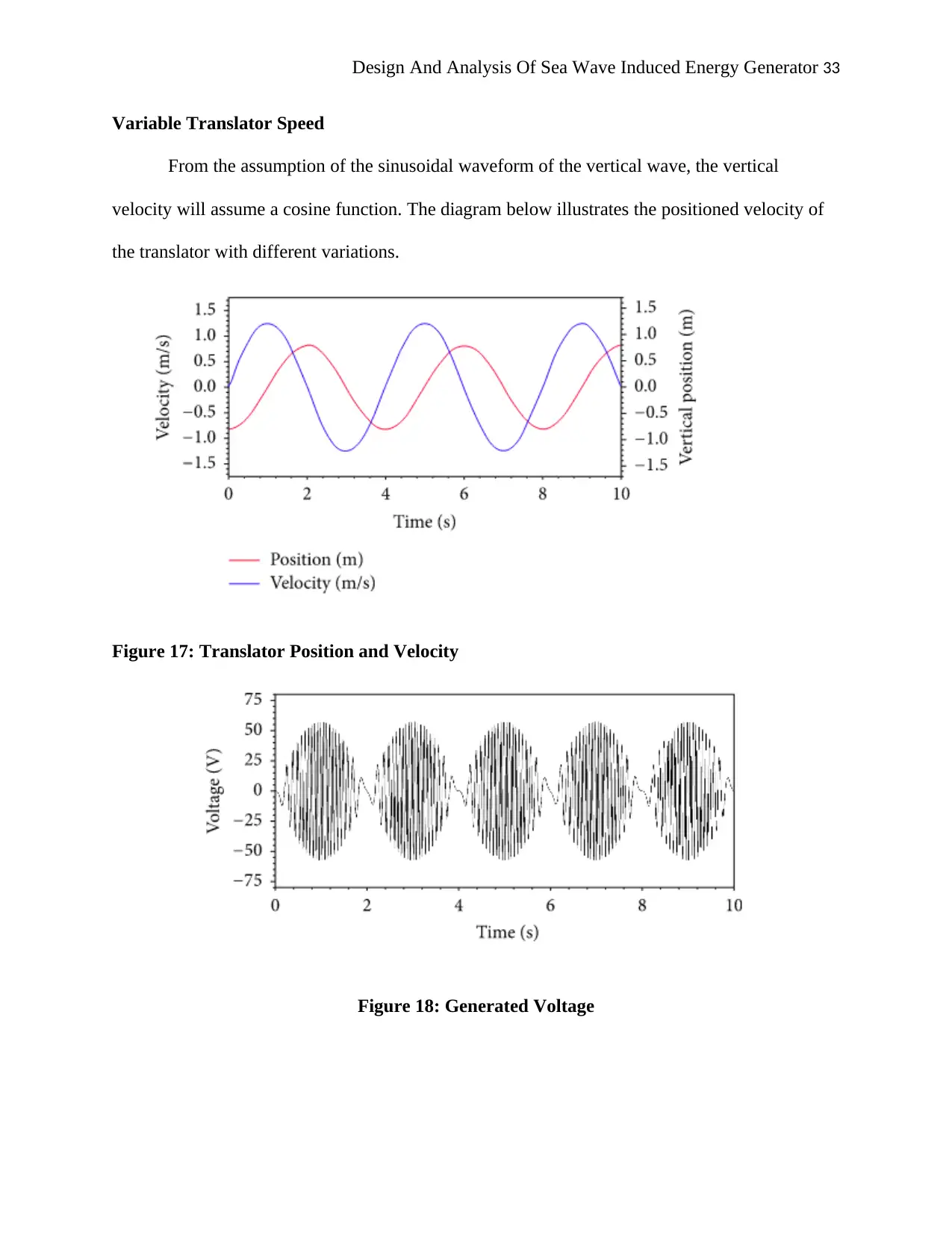
From the assumption of the sinusoidal waveform of the vertical wave, the vertical
velocity will assume a cosine function. The diagram below illustrates the positioned velocity of
the translator with different variations.
Figure 17: Translator Position and Velocity
Figure 18: Generated Voltage
Design And Analysis Of Sea Wave Induced Energy Generator 34
Figure 19: Induced Voltage and Speed
Figure 20: Induced Voltage and current
Figure 19: Induced Voltage and Speed
Figure 20: Induced Voltage and current
Secure Best Marks with AI Grader
Need help grading? Try our AI Grader for instant feedback on your assignments.
Design And Analysis Of Sea Wave Induced Energy Generator 35
Figure 21: Terminal Voltage And Magnetic Flux Linkage
Figure 22: Terminal Current and Voltage
Figure 21: Terminal Voltage And Magnetic Flux Linkage
Figure 22: Terminal Current and Voltage
Design And Analysis Of Sea Wave Induced Energy Generator 36
Figure 23: PLMG Forces
Figure 24: Applied Power and Force
Figure 23: PLMG Forces
Figure 24: Applied Power and Force
Design And Analysis Of Sea Wave Induced Energy Generator 37
Table 3: PLMG dimensions
Table 4: PLMG parameters
Table 3: PLMG dimensions
Table 4: PLMG parameters
Paraphrase This Document
Need a fresh take? Get an instant paraphrase of this document with our AI Paraphraser
Design And Analysis Of Sea Wave Induced Energy Generator 38
4. SUMMARY AND RESEARCH PLAN
With the help of this study and analysis it can be concluded that wave energy is one of
the best sources of renewable energy and it produces very low pollution. It has seen that in
present day two major concerns; one is increasing energy demand and another one is pollution.
Due to increase in population around the globe the energy demand is increasing day by day. The
major part of the energy comes from the fossil fuel which is a non-renewable energy source. As
fossil fuel is limited and the combustion of fossil fuel also increases the pollution level. Wave
energy can be a solution to all the energy demand problems. It is very pleasing that many
governments, countries are trying and showing interest to promote wave energy. Wind passing
the surface of the oceans and seas create the wave. The energy is transferred from the wind to the
wave which is then sued to generate electricity. Increase in shear stress causes the growth of the
waves. Wave height depends on various factors the wind speed, the duration of wind, depth and
topography of the seafloor. Larger waves and powerful waves create more energy which
eventually creates more electricity.
4.1 Future scope
Oregon, USA has become a leader in producing electricity from wave energy. National
canter for wave energy research has been created and world scientists are progressing and
implementing their research. This will boost costal economy of Australia and will fulfil the high
energy demand of developed country. Harnessing electricity from the wave energy is cost
effective economical and environment friendly. The Australia department of energy awarded 37
million dollar to fund 27 wave farm projects. In Pacific Northwest the Northwest National
Marine Renewable energy centre has been established to learn and research about many
Design And Analysis Of Sea Wave Induced Energy Generator 39
renewable marine energy sources including wave energy. 100 million dollar been funded in
CETO wave farm Western Australia to develop multi megawatt system.
The electricity will be used to power HMAS Stirling naval base, two buoys have been
installed and third one is on list. Australian government has awarded 66.46 million dollar to fund
the Ocean power technologies to develop wave farm in Portland. Oceanlinx is developing a
1MW farm in Port Macdonnell. MeyGen project has been planned which will create 1.5MW
electricity will be one of the biggest wave farm. Nowadays Artificial intelligence has been used
to learn algorithms, wave pattern, condition analysis, which decreasing the human involvement
in this sector. Penguin a device developed by Finnish energy company Wello has created a
mountain in the wave energy sector. This device uses rotational energy to generate electricity. If
we are to build successful and efficient marine energy systems in the future, we must apply the
approach of integrated systems. Moreover, requirements, as well as system capabilities, must
also be correctly defined in order to enhance the effectiveness and functionality of emerging
technologies. We can look forward a better and environment friendly upcoming days when we
will use ocean wave power to drive day to day things in our life.
4.2 Limitation
There are some limitations for the wave energy farm. Due to change of currents and
waves there can be coastal erosion. During installing of these devices sea bed is tampered, many
concrete blocks, cable have to be installed. Oils can be released from this devices can harm the
marine life. Marine animals and fishes can be struck in the turbines. Fishing zones are shifted
affecting the fishermen. Noise created by turbines can cause harm to the marine animals. Apart
from these, lack of adequate amount of capital is also play a significant role in resisting the

Design And Analysis Of Sea Wave Induced Energy Generator 40
application of new and advance technology within research that creates problem in fetching
authentic and reliable data.
4.3 Recommendation
4.3.1 Recommendation 1: Stimulation of investment in innovation
Specific Measurable Attainable Realistic Time-
bound
A specific level
of technical
innovation is
essential in order
to achieve
maximum level
of energy. The
successful energy
production
industries need to
increase the level
of investment to
drive the industry
forward.
Key strategies are
required in order to
target high level
investment in
research and
development in
technologies.
Proper investment
and resources can
minimize the
challenges that are
faced by the
technology
developer.
Proper team of
technology
developers is
needed in order to
utilize the
investments and
resources. The
technology
developers need to
focus on inefficient
areas in the case of
innovating new
technologies for
wave energy
The goal of this
project should be
cost-effective. The
energy production
industry in
Australia needs to
focus on
developing high-
performance that
produce huge
amount of energy
from ocean wave.
The time
required
for this
task can
be 6
weeks
4.3.2 Recommendation 2: Improvement of cooperation and coordination
Specific Measurable Attainable Realistic Time-
bound
Cooperation and
coordination
between project
stakeholders can
improve the
performance level
for energy
production. With the
help of strong
cooperation and
All the project
stakeholders need
to develop a
collective effort
that helps in
improving the
quality. It can
also reduce the
level of
competition in
Proper cooperation
can help in making
stakeholders or
researcher more
productive.
Therefore, the
objective of
enhancing the
productivity range
can be attainable. It
The result of this
project needs to
be focused on
identifying best
practices. It can
help in
increasing the
level of
knowledge of all
stakeholders who
The time
required
for this
project
can be 4
weeks
Secure Best Marks with AI Grader
Need help grading? Try our AI Grader for instant feedback on your assignments.
Design And Analysis Of Sea Wave Induced Energy Generator 41
coordination, all
project stakeholders
can be able to meet
the performance
gaps and challenges.
submitting
similar project in
Australia.
can help the energy
production firms to
take the
competitive edge in
highly competitive
market.
are associated
with the project.
4.3.3 Recommendation 3: Implementing technologies for risk assessment
Specific Measurable Attainable Realistic Time-
bound
Implementation of
risk assessment
technologies is
required to achieve
success in the
project. With the
help of risk
assessment
technologies, wave
energy production
industry can be able
to focus on their
efforts for
innovation.
Introducing risk
assessment tools
and technologies
can help in finding
out the potential
challenges
regarding the
project. Therefore,
it can improve the
stability of energy
production. In this
case, the growth of
energy production
organization can
be measured.
Proper use of risk
assessment tools
can determine the
success of the
project. The
industry needs to
focus on
implementing
advanced risk
assessment tools
and technologies
with respect to get
maximum level of
energy.
The result of this
project needs to
define the
minimization of
potential risks.
Therefore, the
organization can
produce huge
amount of
energy from
ocean wave.
The time
required
for this
project
can be 7
weeks
Program of work
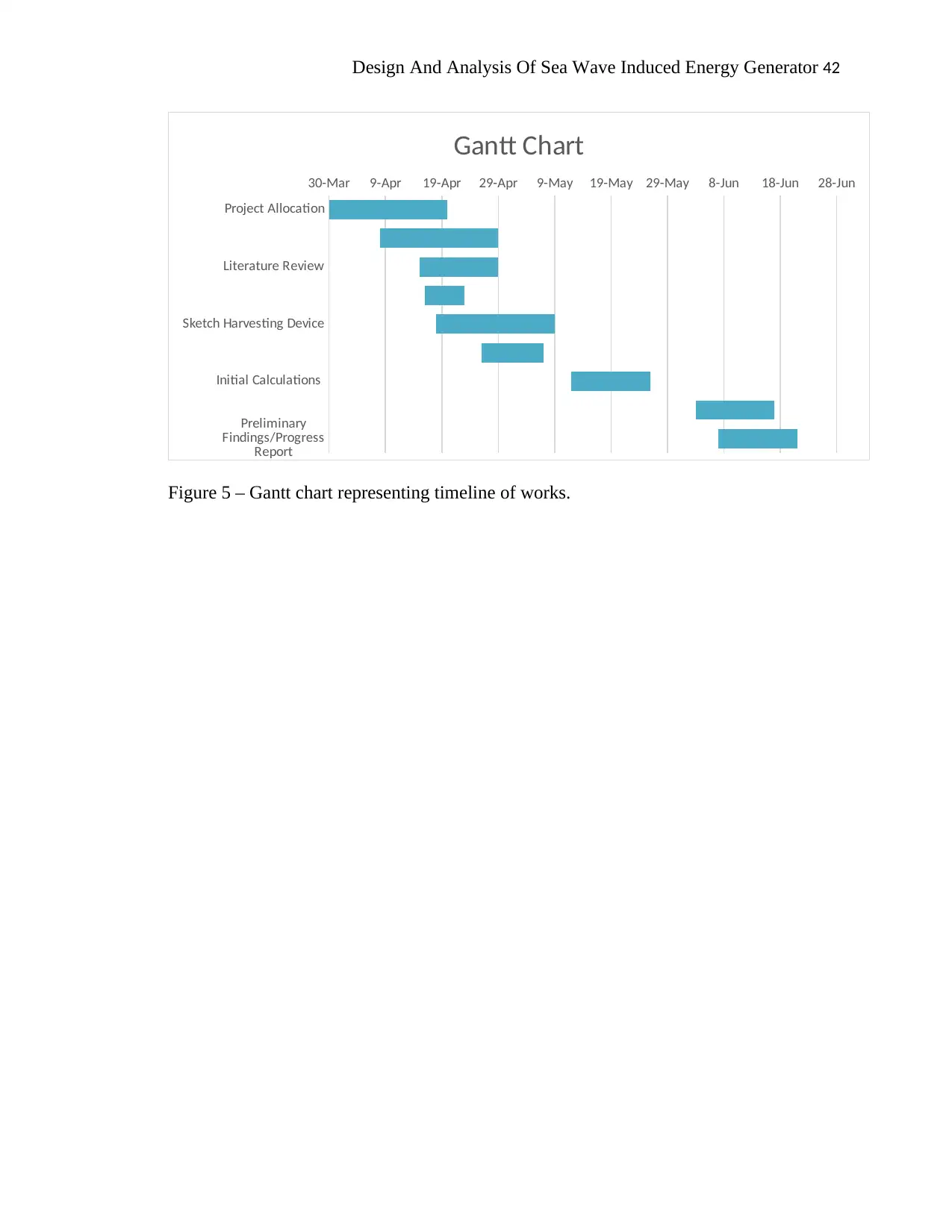
The below Gantt Chart outlines the proposed timeline of works I am undertaking. Some
tasks here overlap, and I will be allocating a few hours a day to each task. All broken down tasks
will be collated and presented together in the final report.
Design And Analysis Of Sea Wave Induced Energy Generator 42
Project Allocation
Literature Review
Sketch Harvesting Device
Initial Calculations
Preliminary
Findings/Progress
Report
30-Mar 9-Apr 19-Apr 29-Apr 9-May 19-May 29-May 8-Jun 18-Jun 28-Jun
Gantt Chart
Figure 5 – Gantt chart representing timeline of works.
Project Allocation
Literature Review
Sketch Harvesting Device
Initial Calculations
Preliminary
Findings/Progress
Report
30-Mar 9-Apr 19-Apr 29-Apr 9-May 19-May 29-May 8-Jun 18-Jun 28-Jun
Gantt Chart
Figure 5 – Gantt chart representing timeline of works.
Design And Analysis Of Sea Wave Induced Energy Generator 43
REFERENCES
Akpınar, A. and Kömürcü, M.İ., 2013. Assessment of wave energy resource of the Black Sea
based on 15-year numerical hindcast data. Applied Energy, 101, pp.502-512.
Alberdi, M., Amundarain, M., Garrido, A. and Garrido, I., 2012. Neural control for voltage dips
ride-through of oscillating water column-based wave energy converter equipped with
doubly-fed induction generator. Renewable Energy, 48, pp.16-26.
Altomare, C., Crespo, A.J., Domínguez, J.M., Gómez-Gesteira, M., Suzuki, T. and Verwaest, T.,
2015. Applicability of smoothed particle hydrodynamics for estimation of sea wave
impact on coastal structures. Coastal Engineering, 96, pp.1-12.
Antonio, F.D.O., 2010. Wave energy utilization: A review of the technologies. Renewable and
sustainable energy reviews, 14(3), pp.899-918.
Astariz, S. and Iglesias, G., 2015. The economics of wave energy: A review. Renewable and
Sustainable Energy Reviews, 45, pp.397-408.
Beirao, P.J.B.F.N. and Malça, C.M.D.S.P., 2014. Design and analysis of buoy geometries for a
wave energy converter. International Journal of Energy and Environmental Engineering,
5(2-3), p.91.
Bento, A.R., Rusu, E., Martinho, P. and Soares, C.G., 2014. Assessment of the changes induced
by a wave energy farm in the nearshore wave conditions. Computers & Geosciences,71,
pp.50-61.
Bracco, G., Giorcelli, E., Mattiazzo, G., Marignetti, F., Carbone, S. and Attaianese, C., 2011,
September. Design and experiments of linear tubular generators for the Inertial Sea Wave
Paraphrase This Document
Need a fresh take? Get an instant paraphrase of this document with our AI Paraphraser
Design And Analysis Of Sea Wave Induced Energy Generator 44
Energy Converter. In 2011 IEEE Energy Conversion Congress and Exposition (pp. 3864-
3871). IEEE.
Cappelli, L., Marignetti, F., Mattiazzo, G., Giorcelli, E., Bracco, G., Carbone, S. and Attaianese,
C., 2013. Linear tubular permanent-magnet generators for the inertial sea wave energy
converter. IEEE Transactions on Industry Applications, 50(3), pp.1817-1828.
Cappelli, L., Marignetti, F., Mattiazzo, G., Giorcelli, E., Bracco, G., Carbone, S. and Attaianese,
C., 2013. Linear tubular permanent-magnet generators for the inertial sea wave energy
converter. IEEE Transactions on Industry Applications, 50(3), pp.1817-1828.
Chen, W., Gao, F., Meng, X., Chen, B. and Ren, A., 2016. W2P: A high-power integrated
generation unit for offshore wind power and ocean wave energy. Ocean
Engineering, 128, pp.41-47.
Coe, R.G. and Neary, V.S., 2014. Review of methods for modeling wave energy converter
survival in extreme sea states.
Coe, R.G. and Neary, V.S., 2014. Review of methods for modeling wave energy converter
survival in extreme sea states.
Collu, M., Kolios, A.J., Chahardehi, A. and Brennan, F.P., 2010. A comparison between the
preliminary design studies of a fixed and a floating support structure for a 5 MW offshore
wind turbine in the North Sea. Marine Renewable and Offshore Wind Energy–Papers.
Di Dio, V., Franzitta, V., Milone, D., Pitruzzella, S., Trapanese, M. and Viola, A., 2014. Design
of bilateral switched reluctance linear generator to convert wave energy: Case study in
Sicily. In Advanced Materials Research (Vol. 860, pp. 1694-1698). Trans Tech
Publications.
Design And Analysis Of Sea Wave Induced Energy Generator 45
Ekström, R., Ekergård, B. and Leijon, M., 2015. Electrical damping of linear generators for wave
energy converters—A review. Renewable and Sustainable Energy Reviews, 42, pp.116-
128.
Franzitta, V., Viola, A. and Trapanese, M., 2014. Design of a transverse flux machine for power
generation from seawaves. Journal of Applied Physics, 115(17), p.17E712.
Goda, Y., 2010. Random seas and design of maritime structures (Vol. 33). World Scientific
Publishing Company.
Gonçalves, M., Martinho, P. and Soares, C.G., 2014. Assessment of wave energy in the Canary
Islands. Renewable Energy, 68, pp.774-784.
Katalinić, M., Ćorak, M. and Parunov, J., 2014, October. Analysis of wave heights and wind
speeds in the Adriatic Sea. In 3rd International Conference on Maritime Technology and
Engineering, Lisabon, Portugal, July (pp. 5-7).
Kazmierkowski, M.P. and Jasinski, M., 2010, May. Power electronics for renewable sea wave
energy. In 2010 12th International Conference on Optimization of Electrical and
Electronic Equipment (pp. 4-9). IEEE.
López, I., Andreu, J., Ceballos, S., de Alegría, I.M. and Kortabarria, I., 2013. Review of wave
energy technologies and the necessary power-equipment. Renewable and sustainable
energy reviews, 27, pp.413-434.
Memon, A.H., bin Ibrahim, T. and Perumal, N., 2014, June. Portable and pico-scale linear
generator for wave energy conversion. In 2014 5th International Conference on
Intelligent and Advanced Systems (ICIAS) (pp. 1-4). IEEE.
Design And Analysis Of Sea Wave Induced Energy Generator 46
Mendes, R.P.G., Calado, M.R.A. and Mariano, S.J.P.S., 2012. Wave energy potential in
Portugal–Assessment based on probabilistic description of ocean waves parameters.
Renewable energy, 47, pp.1-8.
Nam, B.W., Hong, S.Y., Shin, S.H., Hong, S.W. and Kim, K.B., 2012, January. Prediction of the
hydrodynamic performance of the floating pendulum wave energy converter in regular
and irregular waves. In The Twenty-second International Offshore and Polar
Engineering Conference. International Society of Offshore and Polar Engineers.
O’Sullivan, D.L. and Lewis, A.W., 2011. Generator selection and comparative performance in
offshore oscillating water column ocean wave energy converters. IEEE transactions on
energy conversion, 26(2), pp.603-614.
O’Sullivan, D.L. and Lewis, A.W., 2012. Generator selection and comparative performance in
offshore oscillating water column ocean wave energy converters. IEEE transactions on
energy conversion, 26(2), pp.603-614.
Park, J.Y., Shin, S.H., Hong, K.Y. and Kim, S.H., 2012, January. A study on the wave response
and efficiency of a pendulum wave energy converter. In The Twenty-second
International Offshore and Polar Engineering Conference. International Society of
Offshore and Polar Engineers.
Parkinson, S.C., Dragoon, K., Reikard, G., García-Medina, G., Özkan-Haller, H.T. and Brekken,
T.K., 2015. Integrating ocean wave energy at large-scales: A study of the US Pacific
Northwest. Renewable Energy, 76, pp.551-559.
Prudell, J., Stoddard, M., Amon, E., Brekken, T.K. and Von Jouanne, A., 2010. A permanent-
magnet tubular linear generator for ocean wave energy conversion. IEEE Transactions
on Industry Applications, 46(6), pp.2392-2400.
Secure Best Marks with AI Grader
Need help grading? Try our AI Grader for instant feedback on your assignments.
Design And Analysis Of Sea Wave Induced Energy Generator 47
Ragnarsson, P., Pluymers, B., Donders, S. and Desmet, W., 2010. Subcomponent modelling of
input parameters for statistical energy analysis by using a wave-based boundary
condition. Journal of sound and vibration, 329(1), pp.96-108.
Ragnarsson, P., Pluymers, B., Donders, S. and Desmet, W., 2010. Subcomponent modelling of
input parameters for statistical energy analysis by using a wave-based boundary
condition. Journal of sound and vibration, 329(1), pp.96-108.
Roland, A. and Ardhuin, F., 2014. On the developments of spectral wave models: numerics and
parameterizations for the coastal ocean. Ocean Dynamics, 64(6), pp.833-846.
Samrat, N.H., Ahmad, N.B., Choudhury, I.A. and Taha, Z.B., 2014. Modeling, control, and
simulation of battery storage photovoltaic-wave energy hybrid renewable power
generation systems for island electrification in Malaysia. The Scientific World
Journal, 2014.
Soares, C.G., Bento, A.R., Gonçalves, M., Silva, D. and Martinho, P., 2014. Numerical
evaluation of the wave energy resource along the Atlantic European coast. Computers &
Geosciences, 71, pp.37-49.
Soltanmohamadi, R. and Lakzian, E., 2016. Improved design of Wells turbine for wave energy
conversion using entropy generation. Meccanica, 51(8), pp.1713-1722.
Stratigaki, V., Troch, P., Stallard, T., Forehand, D., Kofoed, J., Folley, M., Benoit, M., Babarit,
A. and Kirkegaard, J., 2014. Wave basin experiments with large wave energy converter
arrays to study interactions between the converters and effects on other users in the sea
and the coastal area. Energies, 7(2), pp.701-734.
Ragnarsson, P., Pluymers, B., Donders, S. and Desmet, W., 2010. Subcomponent modelling of
input parameters for statistical energy analysis by using a wave-based boundary
condition. Journal of sound and vibration, 329(1), pp.96-108.
Ragnarsson, P., Pluymers, B., Donders, S. and Desmet, W., 2010. Subcomponent modelling of
input parameters for statistical energy analysis by using a wave-based boundary
condition. Journal of sound and vibration, 329(1), pp.96-108.
Roland, A. and Ardhuin, F., 2014. On the developments of spectral wave models: numerics and
parameterizations for the coastal ocean. Ocean Dynamics, 64(6), pp.833-846.
Samrat, N.H., Ahmad, N.B., Choudhury, I.A. and Taha, Z.B., 2014. Modeling, control, and
simulation of battery storage photovoltaic-wave energy hybrid renewable power
generation systems for island electrification in Malaysia. The Scientific World
Journal, 2014.
Soares, C.G., Bento, A.R., Gonçalves, M., Silva, D. and Martinho, P., 2014. Numerical
evaluation of the wave energy resource along the Atlantic European coast. Computers &
Geosciences, 71, pp.37-49.
Soltanmohamadi, R. and Lakzian, E., 2016. Improved design of Wells turbine for wave energy
conversion using entropy generation. Meccanica, 51(8), pp.1713-1722.
Stratigaki, V., Troch, P., Stallard, T., Forehand, D., Kofoed, J., Folley, M., Benoit, M., Babarit,
A. and Kirkegaard, J., 2014. Wave basin experiments with large wave energy converter
arrays to study interactions between the converters and effects on other users in the sea
and the coastal area. Energies, 7(2), pp.701-734.
Design And Analysis Of Sea Wave Induced Energy Generator 48
Stumpp, M., Trübenbach, K., Brennecke, D., Hu, M.Y. and Melzner, F., 2012. Resource
allocation and extracellular acid–base status in the sea urchin Strongylocentrotus
droebachiensis in response to CO2 induced seawater acidification. Aquatic Toxicology,
110, pp.194-207.
Titah-Benbouzid, H. and Benbouzid, M., 2014, November. Ocean wave energy extraction: Up-
to-date technologies review and evaluation. In 2014 International Power Electronics and
Application Conference and Exposition (pp. 338-342). IEEE.
Titah-Benbouzid, H. and Benbouzid, M., 2014, November. Ocean wave energy extraction: Up-
to-date technologies review and evaluation. In 2014 International Power Electronics and
Application Conference and Exposition (pp. 338-342). IEEE.
Veigas, M., Carballo, R. and Iglesias, G., 2014. Wave and offshore wind energy on an
island. Energy for Sustainable Development, 22, pp.57-65.
Vermaak, R. and Kamper, M.J., 2011. Design aspects of a novel topology air-cored permanent
magnet linear generator for direct drive wave energy converters. IEEE Transactions on
Industrial Electronics, 59(5), pp.2104-2115.
Vertechy, R., Fontana, M., Papini, G.R. and Bergamasco, M., 2013, April. Oscillating-water-
column wave-energy-converter based on dielectric elastomer generator. In Electroactive
Polymer Actuators and Devices (EAPAD) 2013 (Vol. 8687, p. 86870I). International
Society for Optics and Photonics.
1 out of 48
Your All-in-One AI-Powered Toolkit for Academic Success.
+13062052269
info@desklib.com
Available 24*7 on WhatsApp / Email
![[object Object]](/_next/static/media/star-bottom.7253800d.svg)
Unlock your academic potential
© 2024 | Zucol Services PVT LTD | All rights reserved.

