Electrical Engineering: PFC AC Drive Design and Development Report
VerifiedAdded on 2020/03/16
|12
|1627
|83
Report
AI Summary
This report details a project focused on the design and development of a Power Factor Correction (PFC) AC drive using a Variable Frequency Drive (VFD) system. The project aimed to improve power factor, reduce electricity bills, and manage input power based on system demand. The student's role involved designing the inverter and converter sections, including simulations, prototyping, and the design of a DC-DC buck converter. The report describes the application of engineering knowledge, including the use of power semiconductor devices, PWM switching techniques, and the design of a three-phase inverter. The project involved addressing issues such as power supply failures and component installation, and the student highlights collaborative work and the benefits of the designed PFC system, such as reduced starting current and improved power quality. The report concludes with an overview of the project's objectives, the student's contributions, and the comparison of results with non-PFC systems, including an energy appraisal.

Competency Demonstration Report
Career Episode 2
Career Episode 2
Paraphrase This Document
Need a fresh take? Get an instant paraphrase of this document with our AI Paraphraser
CE 2.1 Project Information
Name of the project: Design and development of PFC through VFD
Location of the project: Karachi
Project Duration: (Please fill)
Organization: (Please fill)
Role and Designation during the time: Team Member
CE 2.2 Project Background
CE 2.2.1 Characteristics of the project
I had conducted this project to design and develop of Power Factor Correction (PFC)
throughout Variable Frequency Drive (VFD). In this project, induction motor is used for meeting
client’s requirements. When there is supply of power to induction motor at recommended
specifications, then it runs at high speed. Driving in addition to controlling of induction motor
are the major concerns into energy aware world. There is availability of VFD into various AC-
AC as well as DC-DC topologies to correct of the power factor. The topologies are used into
open as well as close loop where in this project work, open loop system is mainly focused.
CE 2.2.2 Objectives developed for the project
Following are the objectives to develop PFC AC drive through VFD:
To design and develop of compact and low cost PFC AC Drive
To reduce of electricity bills

SeniorProjectAdvisorIntern.SupervisorElectronicsEngineerElectronicsEngineerElectronicsEngineer To manage of input power based on the system demand
CE 2.2.3 My Area of work
I had divided the project work into two section such as inverter and converter section.
Inverter involves of simulation, design and prototype of the project work while converter section
consists of design of dc-dc converter of the buck type. I had done the design on discrete on-board
MOSFET. It is essential to store of regenerated energy to super capacitor based battery.
CE 2.2.4 Project Group
⊘ This is a preview!⊘
Do you want full access?
Subscribe today to unlock all pages.

Trusted by 1+ million students worldwide
Figure 1: People involved in the project
CE 2.2.5 My responsibilities throughout the project
I had provided the description of the power semiconductor devices to the team members
so that they are aware of the project requirements. I had provided justification of the sinusoidal
PWM switching techniques is followed by the switch mode converter as well as its types. I had
reviewed the end used isolation types.
CE 2.3 Distinctive Activity
CE 2.3.1 Comprehending the Theory of the project
I had drawn the block diagram for PFC ac drive. There is rectifier which converts ac
input to unregulated dc voltage. The harmonics into the filter is removed by the filter capacitor in
order to generate of three phase ac for the electric motor. When the load is overhauling the
motor, then there is a rise into the dc bus voltage. The overvoltage is being sensed by dc-dc
converter and energy within the bus capacitor is being relocated into energy storage part.
Paraphrase This Document
Need a fresh take? Get an instant paraphrase of this document with our AI Paraphraser

Figure 2: Block diagram of the PFC AC Drive
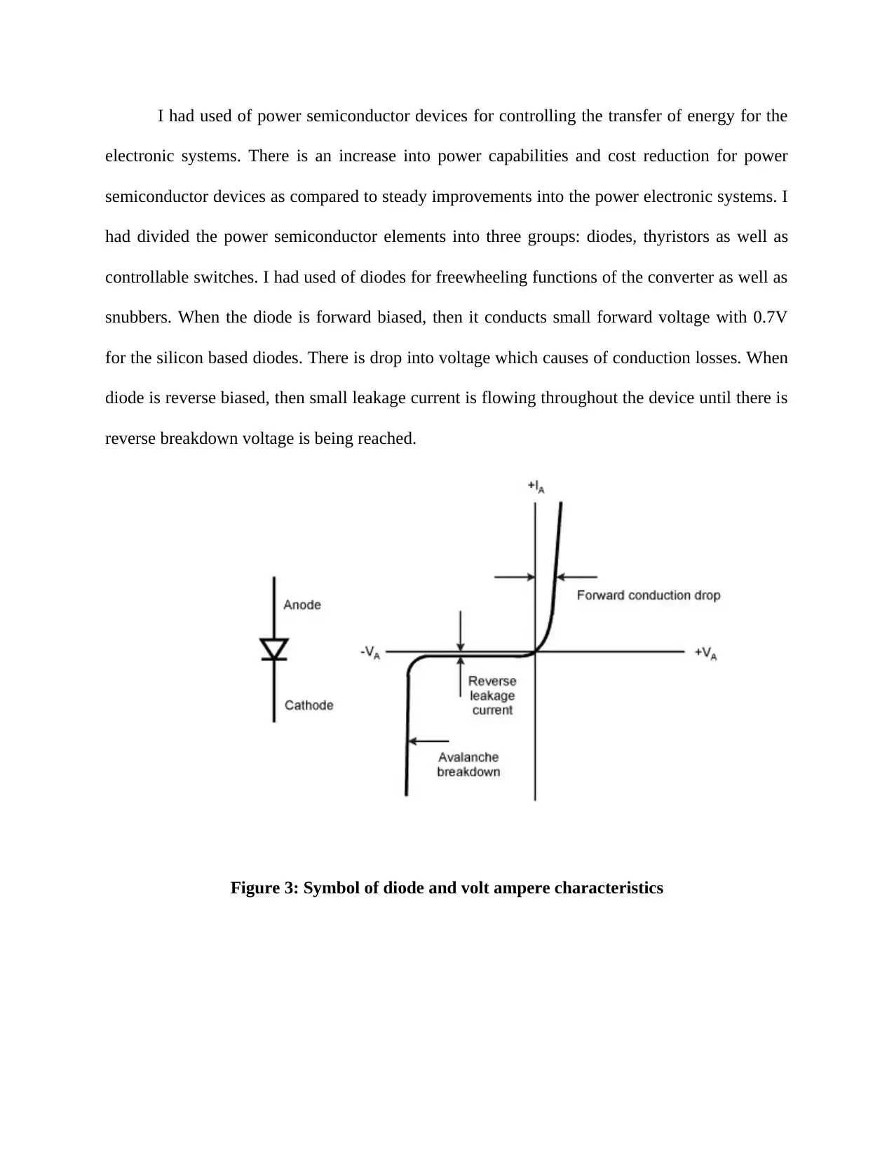
I had used of power semiconductor devices for controlling the transfer of energy for the
electronic systems. There is an increase into power capabilities and cost reduction for power
semiconductor devices as compared to steady improvements into the power electronic systems. I
had divided the power semiconductor elements into three groups: diodes, thyristors as well as
controllable switches. I had used of diodes for freewheeling functions of the converter as well as
snubbers. When the diode is forward biased, then it conducts small forward voltage with 0.7V
for the silicon based diodes. There is drop into voltage which causes of conduction losses. When
diode is reverse biased, then small leakage current is flowing throughout the device until there is
reverse breakdown voltage is being reached.
Figure 3: Symbol of diode and volt ampere characteristics
⊘ This is a preview!⊘
Do you want full access?
Subscribe today to unlock all pages.

Trusted by 1+ million students worldwide
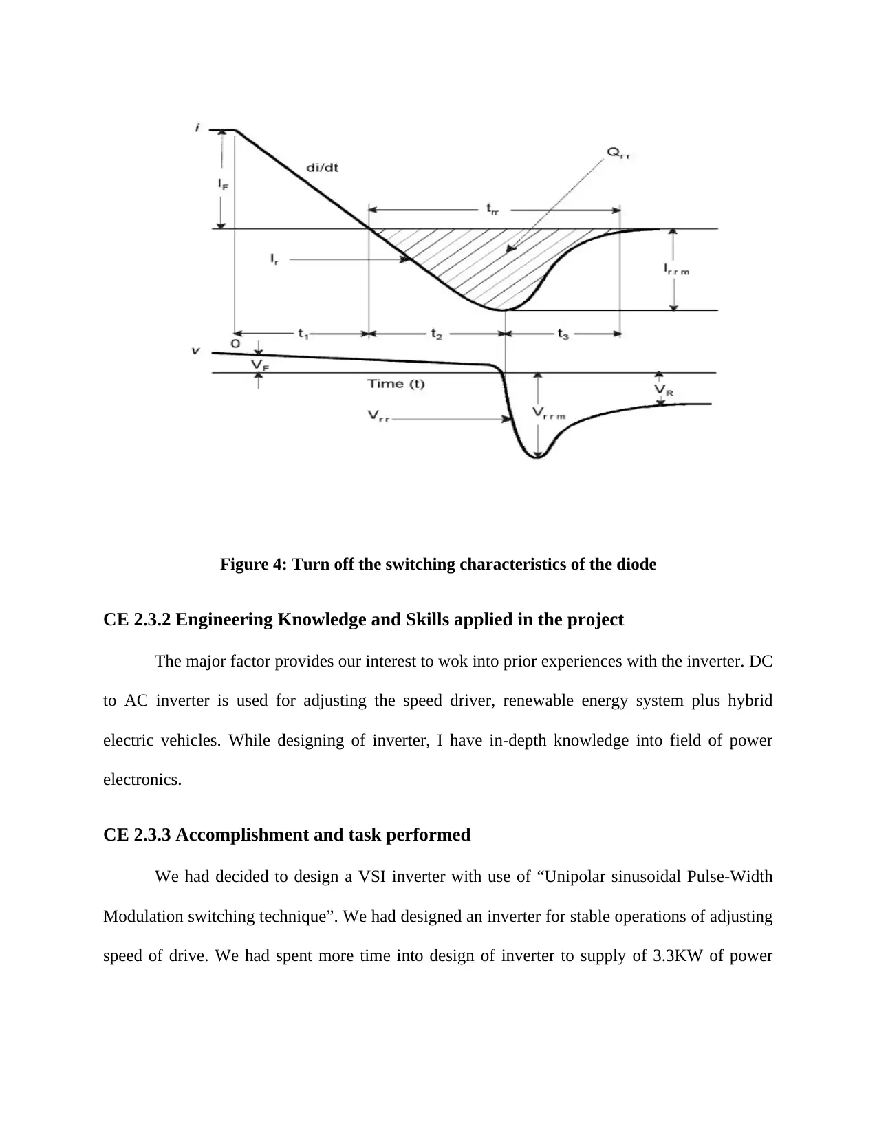
Figure 4: Turn off the switching characteristics of the diode
CE 2.3.2 Engineering Knowledge and Skills applied in the project
The major factor provides our interest to wok into prior experiences with the inverter. DC
to AC inverter is used for adjusting the speed driver, renewable energy system plus hybrid
electric vehicles. While designing of inverter, I have in-depth knowledge into field of power
electronics.
CE 2.3.3 Accomplishment and task performed
We had decided to design a VSI inverter with use of “Unipolar sinusoidal Pulse-Width
Modulation switching technique”. We had designed an inverter for stable operations of adjusting
speed of drive. We had spent more time into design of inverter to supply of 3.3KW of power
Paraphrase This Document
Need a fresh take? Get an instant paraphrase of this document with our AI Paraphraser

with a load current of 15A. Power requirements come from 0.4hp induction motor that is used as
load. I had designed the three-phase inverter as follows:
load. I had designed the three-phase inverter as follows:
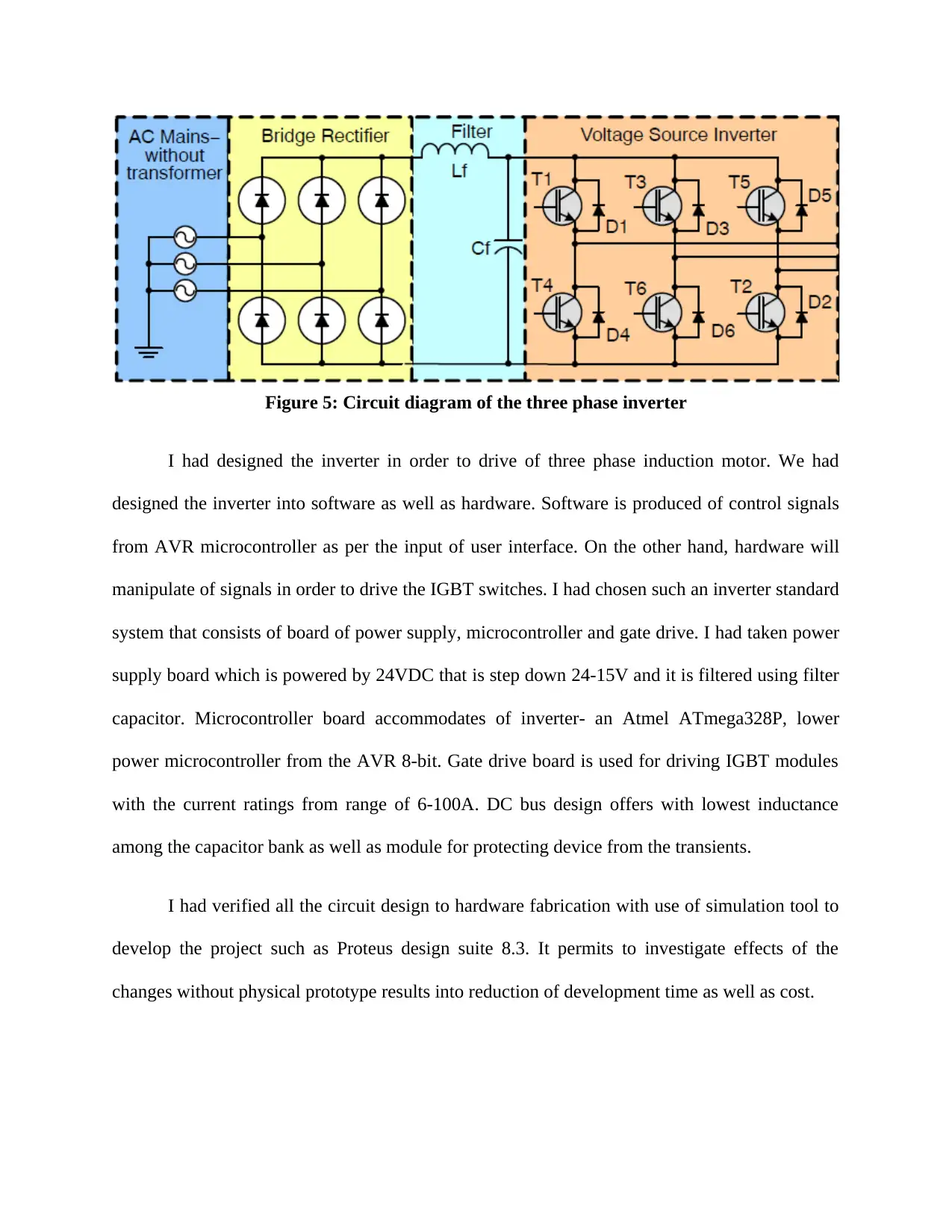
Figure 5: Circuit diagram of the three phase inverter
I had designed the inverter in order to drive of three phase induction motor. We had
designed the inverter into software as well as hardware. Software is produced of control signals
from AVR microcontroller as per the input of user interface. On the other hand, hardware will
manipulate of signals in order to drive the IGBT switches. I had chosen such an inverter standard
system that consists of board of power supply, microcontroller and gate drive. I had taken power
supply board which is powered by 24VDC that is step down 24-15V and it is filtered using filter
capacitor. Microcontroller board accommodates of inverter- an Atmel ATmega328P, lower
power microcontroller from the AVR 8-bit. Gate drive board is used for driving IGBT modules
with the current ratings from range of 6-100A. DC bus design offers with lowest inductance
among the capacitor bank as well as module for protecting device from the transients.
I had verified all the circuit design to hardware fabrication with use of simulation tool to
develop the project such as Proteus design suite 8.3. It permits to investigate effects of the
changes without physical prototype results into reduction of development time as well as cost.
⊘ This is a preview!⊘
Do you want full access?
Subscribe today to unlock all pages.

Trusted by 1+ million students worldwide
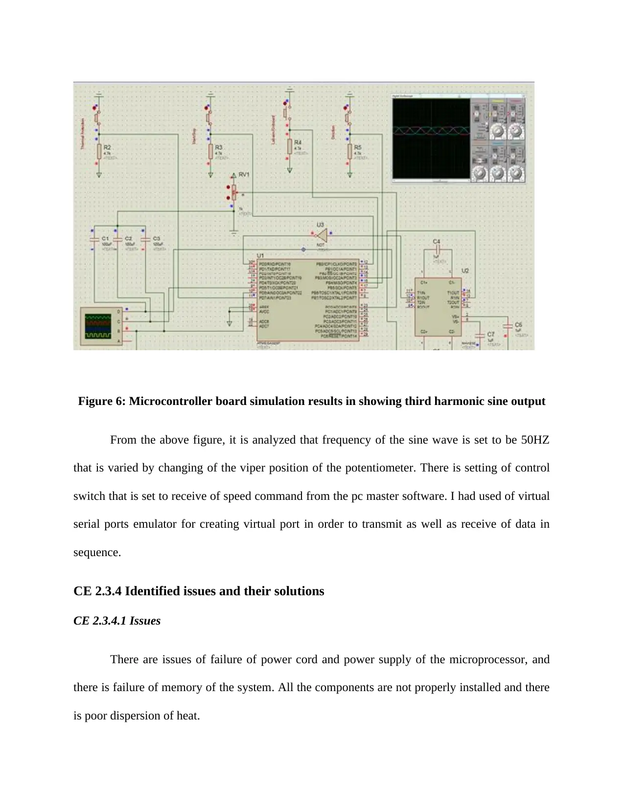
Figure 6: Microcontroller board simulation results in showing third harmonic sine output
From the above figure, it is analyzed that frequency of the sine wave is set to be 50HZ
that is varied by changing of the viper position of the potentiometer. There is setting of control
switch that is set to receive of speed command from the pc master software. I had used of virtual
serial ports emulator for creating virtual port in order to transmit as well as receive of data in
sequence.
CE 2.3.4 Identified issues and their solutions
CE 2.3.4.1 Issues
There are issues of failure of power cord and power supply of the microprocessor, and
there is failure of memory of the system. All the components are not properly installed and there
is poor dispersion of heat.
Paraphrase This Document
Need a fresh take? Get an instant paraphrase of this document with our AI Paraphraser
CE 2.3.4.2 Solutions
When the power cord and power supply is failed, then it is replaced by another power
cord and power supply. Testing should be done on the electrical equipments before it is used for
the project work. All the peripherals of the system, boards and socketed components should be
reseated properly. The CPU heat sink should be checked when it is required.
CE 2.3.5 Plan to produce creative and innovative work
In this project work, I had designed PF using DC drive, developed it as well as tested it
within the laboratory to access the performance. I had to control of speed of motor as well as
torque and maintain a PF upto 0.97. The main feature of this project is to lower the cost design.
When the motor is started across the line, then there is reduction of starting current of motor by
60 percent. It permits to reduce peak demand charges and there is reduction of the electricity
bills. Manual mode of the process permitted smooth speed transitions from 0 Hz-100 Hz. The
capacitor bank is offered distribution as well as transmission circuits with the power factor
corrections. It reduces KVA demand, billed along with improved of the voltage regulations. It is
switched both in as well as out based on the conditions of load. It provides of quality power with
an increase into use of electronic power equipments.
CE 2.3.6 Collaborative work
The time served experience of my project supervisor helped me a lot to develop my
initial project plan. He had provided me pre-presentation suggestions which help me to prepare
the final project report. Technical assistance provided to me which help me in designing of
power inverter that reduces the research load. For this, I had completed the project work on time.
My team members also helped me in my work and kept team optimistic which results into
success of my project study.
CE 2.4 Project Review
CE 2.4.1 Project overview
This particular report is focused on design, construction as well as testing of PFC through
VFD. This project provides method to save wasted energy which is generated during the starting
period of the induction motor. In order to control speed drive, DC to AC inverters are being used.
Power electronics knowledge is required for designing of the inverter in order to meet with the
project objectives.
CE 2.4.2 My contribution to work
I had designed and developed compact and lower cost PFC AC drive. Development over
the PFC helps to reduce the electricity bills. I had compared results of non PFC systems to
analyze the differences. I had also carried out an energy appraisal for this project work.
⊘ This is a preview!⊘
Do you want full access?
Subscribe today to unlock all pages.

Trusted by 1+ million students worldwide
1 out of 12
Related Documents
Your All-in-One AI-Powered Toolkit for Academic Success.
+13062052269
info@desklib.com
Available 24*7 on WhatsApp / Email
![[object Object]](/_next/static/media/star-bottom.7253800d.svg)
Unlock your academic potential
Copyright © 2020–2026 A2Z Services. All Rights Reserved. Developed and managed by ZUCOL.


