Instrumentation Amplifier Design: A Comprehensive Guide to Differential Amplifiers and Applications
VerifiedAdded on 2023/04/25
|6
|1978
|218
AI Summary
In this report we will discuss about Instrumentation amplifier and below are the summaries point:-
An instrumentation amplifier is a differential amplifier with input buffer amplifiers, ideal for measurements and testing equipment.
The design of an instrumentation amplifier involves combining three operational amplifiers and resistors.
Instrumentation amplifiers are commonly used to amplify voltage from a Wheatstone bridge, providing a balanced output.
Contribute Materials
Your contribution can guide someone’s learning journey. Share your
documents today.
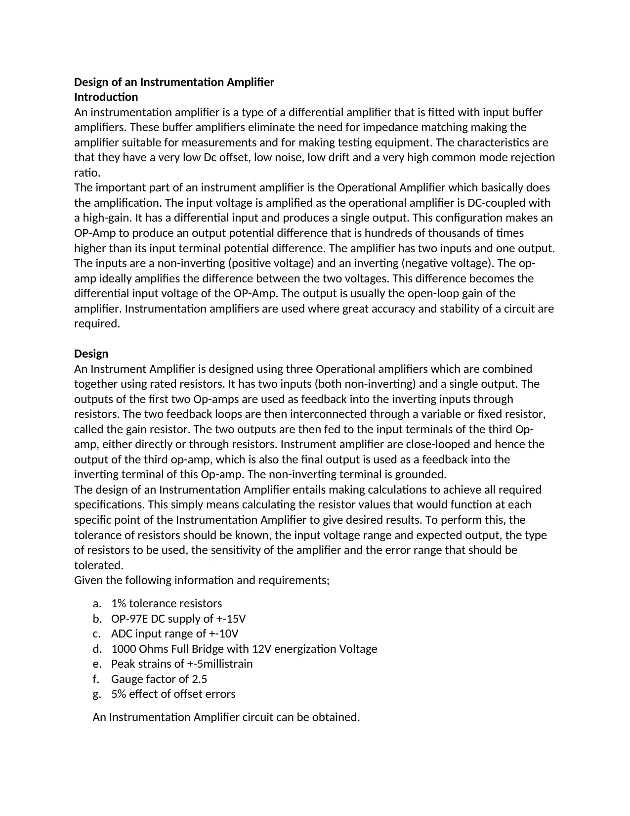
Design of an Instrumentation Amplifier
Introduction
An instrumentation amplifier is a type of a differential amplifier that is fitted with input buffer
amplifiers. These buffer amplifiers eliminate the need for impedance matching making the
amplifier suitable for measurements and for making testing equipment. The characteristics are
that they have a very low Dc offset, low noise, low drift and a very high common mode rejection
ratio.
The important part of an instrument amplifier is the Operational Amplifier which basically does
the amplification. The input voltage is amplified as the operational amplifier is DC-coupled with
a high-gain. It has a differential input and produces a single output. This configuration makes an
OP-Amp to produce an output potential difference that is hundreds of thousands of times
higher than its input terminal potential difference. The amplifier has two inputs and one output.
The inputs are a non-inverting (positive voltage) and an inverting (negative voltage). The op-
amp ideally amplifies the difference between the two voltages. This difference becomes the
differential input voltage of the OP-Amp. The output is usually the open-loop gain of the
amplifier. Instrumentation amplifiers are used where great accuracy and stability of a circuit are
required.
Design
An Instrument Amplifier is designed using three Operational amplifiers which are combined
together using rated resistors. It has two inputs (both non-inverting) and a single output. The
outputs of the first two Op-amps are used as feedback into the inverting inputs through
resistors. The two feedback loops are then interconnected through a variable or fixed resistor,
called the gain resistor. The two outputs are then fed to the input terminals of the third Op-
amp, either directly or through resistors. Instrument amplifier are close-looped and hence the
output of the third op-amp, which is also the final output is used as a feedback into the
inverting terminal of this Op-amp. The non-inverting terminal is grounded.
The design of an Instrumentation Amplifier entails making calculations to achieve all required
specifications. This simply means calculating the resistor values that would function at each
specific point of the Instrumentation Amplifier to give desired results. To perform this, the
tolerance of resistors should be known, the input voltage range and expected output, the type
of resistors to be used, the sensitivity of the amplifier and the error range that should be
tolerated.
Given the following information and requirements;
a. 1% tolerance resistors
b. OP-97E DC supply of +-15V
c. ADC input range of +-10V
d. 1000 Ohms Full Bridge with 12V energization Voltage
e. Peak strains of +-5millistrain
f. Gauge factor of 2.5
g. 5% effect of offset errors
An Instrumentation Amplifier circuit can be obtained.
Secure Best Marks with AI Grader
Need help grading? Try our AI Grader for instant feedback on your assignments.
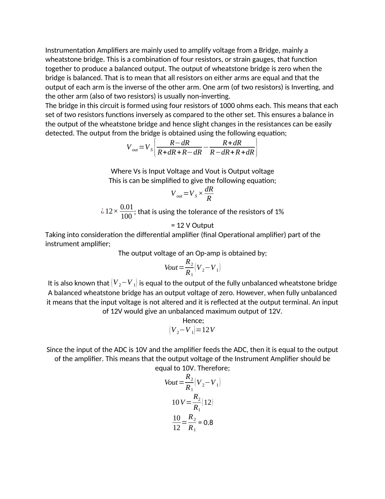
Instrumentation Amplifiers are mainly used to amplify voltage from a Bridge, mainly a
wheatstone bridge. This is a combination of four resistors, or strain gauges, that function
together to produce a balanced output. The output of wheatstone bridge is zero when the
bridge is balanced. That is to mean that all resistors on either arms are equal and that the
output of each arm is the inverse of the other arm. One arm (of two resistors) is Inverting, and
the other arm (also of two resistors) is usually non-inverting.
The bridge in this circuit is formed using four resistors of 1000 ohms each. This means that each
set of two resistors functions inversely as compared to the other set. This ensures a balance in
the output of the wheatstone bridge and hence slight changes in the resistances can be easily
detected. The output from the bridge is obtained using the following equation;
V out =V S { R−dR
R+dR +R−dR − R+dR
R−dR+ R +dR }
Where Vs is Input Voltage and Vout is Output voltage
This is can be simplified to give the following equation;
V out =V S × dR
R
¿ 12× 0.01
100 ; that is using the tolerance of the resistors of 1%
= 12 V Output
Taking into consideration the differential amplifier (final Operational amplifier) part of the
instrument amplifier;
The output voltage of an Op-amp is obtained by;
Vout= R2
R1
( V 2−V 1 )
It is also known that ( V 2−V 1 ) is equal to the output of the fully unbalanced wheatstone bridge
A balanced wheatstone bridge has an output voltage of zero. However, when fully unbalanced
it means that the input voltage is not altered and it is reflected at the output terminal. An input
of 12V would give an unbalanced maximum output of 12V.
Hence;
( V 2−V 1 ) =12V
Since the input of the ADC is 10V and the amplifier feeds the ADC, then it is equal to the output
of the amplifier. This means that the output voltage of the Instrument Amplifier should be
equal to 10V. Therefore;
Vout = R2
R1
( V 2−V 1 )
10 V = R2
R1
( 12 )
10
12 = R2
R1
= 0.8
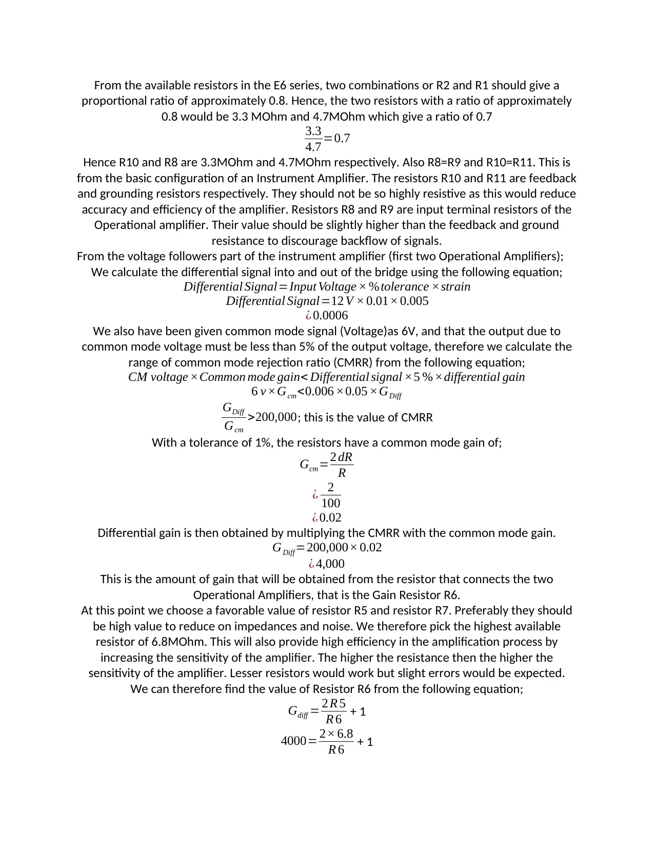
From the available resistors in the E6 series, two combinations or R2 and R1 should give a
proportional ratio of approximately 0.8. Hence, the two resistors with a ratio of approximately
0.8 would be 3.3 MOhm and 4.7MOhm which give a ratio of 0.7
3.3
4.7 =0.7
Hence R10 and R8 are 3.3MOhm and 4.7MOhm respectively. Also R8=R9 and R10=R11. This is
from the basic configuration of an Instrument Amplifier. The resistors R10 and R11 are feedback
and grounding resistors respectively. They should not be so highly resistive as this would reduce
accuracy and efficiency of the amplifier. Resistors R8 and R9 are input terminal resistors of the
Operational amplifier. Their value should be slightly higher than the feedback and ground
resistance to discourage backflow of signals.
From the voltage followers part of the instrument amplifier (first two Operational Amplifiers);
We calculate the differential signal into and out of the bridge using the following equation;
Differential Signal=Input Voltage × %tolerance ×strain
Differential Signal=12 V × 0.01× 0.005
¿ 0.0006
We also have been given common mode signal (Voltage)as 6V, and that the output due to
common mode voltage must be less than 5% of the output voltage, therefore we calculate the
range of common mode rejection ratio (CMRR) from the following equation;
CM voltage ×Common mode gain< Differential signal ×5 % ×differential gain
6 v ×Gcm<0.006 ×0.05 ×GDiff
GDiff
Gcm
>200,000; this is the value of CMRR
With a tolerance of 1%, the resistors have a common mode gain of;
Gcm=2 dR
R
¿ 2
100
¿ 0.02
Differential gain is then obtained by multiplying the CMRR with the common mode gain.
GDiff=200,000× 0.02
¿ 4,000
This is the amount of gain that will be obtained from the resistor that connects the two
Operational Amplifiers, that is the Gain Resistor R6.
At this point we choose a favorable value of resistor R5 and resistor R7. Preferably they should
be high value to reduce on impedances and noise. We therefore pick the highest available
resistor of 6.8MOhm. This will also provide high efficiency in the amplification process by
increasing the sensitivity of the amplifier. The higher the resistance then the higher the
sensitivity of the amplifier. Lesser resistors would work but slight errors would be expected.
We can therefore find the value of Resistor R6 from the following equation;
Gdiff = 2 R 5
R 6 + 1
4000= 2× 6.8
R 6 + 1
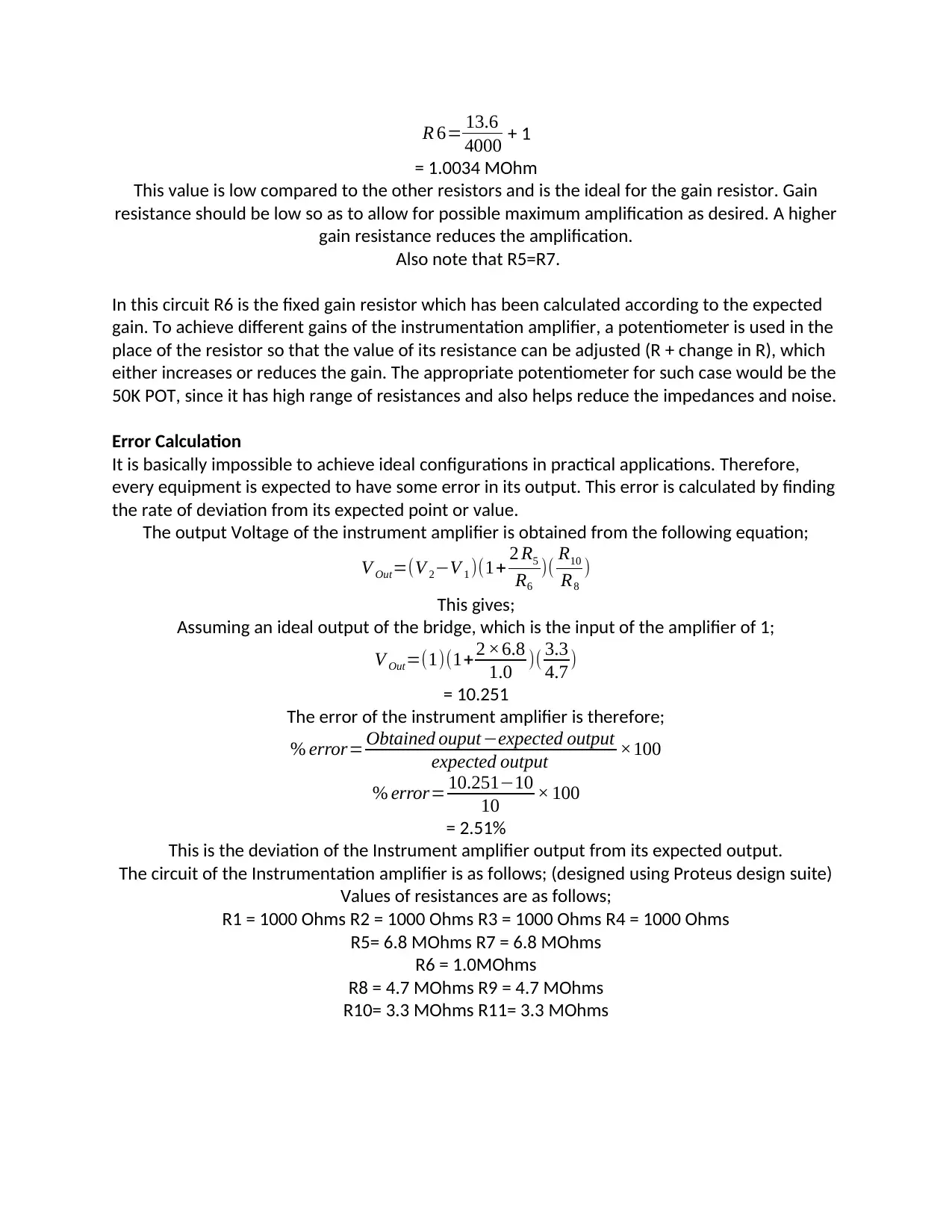
R 6= 13.6
4000 + 1
= 1.0034 MOhm
This value is low compared to the other resistors and is the ideal for the gain resistor. Gain
resistance should be low so as to allow for possible maximum amplification as desired. A higher
gain resistance reduces the amplification.
Also note that R5=R7.
In this circuit R6 is the fixed gain resistor which has been calculated according to the expected
gain. To achieve different gains of the instrumentation amplifier, a potentiometer is used in the
place of the resistor so that the value of its resistance can be adjusted (R + change in R), which
either increases or reduces the gain. The appropriate potentiometer for such case would be the
50K POT, since it has high range of resistances and also helps reduce the impedances and noise.
Error Calculation
It is basically impossible to achieve ideal configurations in practical applications. Therefore,
every equipment is expected to have some error in its output. This error is calculated by finding
the rate of deviation from its expected point or value.
The output Voltage of the instrument amplifier is obtained from the following equation;
V Out=(V 2−V 1 )(1+ 2 R5
R6
)( R10
R8
)
This gives;
Assuming an ideal output of the bridge, which is the input of the amplifier of 1;
V Out=(1)(1+ 2 ×6.8
1.0 )( 3.3
4.7 )
= 10.251
The error of the instrument amplifier is therefore;
% error= Obtained ouput −expected output
expected output ×100
% error= 10.251−10
10 × 100
= 2.51%
This is the deviation of the Instrument amplifier output from its expected output.
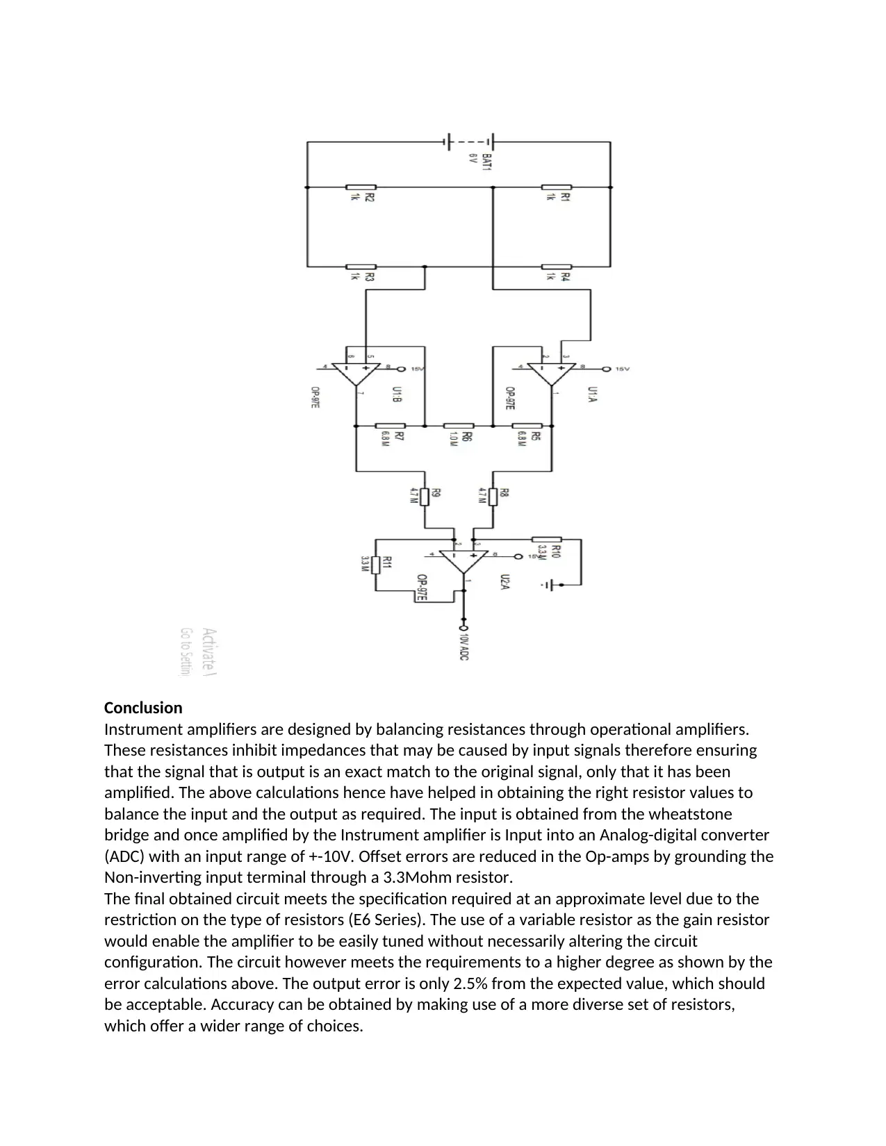
The circuit of the Instrumentation amplifier is as follows; (designed using Proteus design suite)
Values of resistances are as follows;
R1 = 1000 Ohms R2 = 1000 Ohms R3 = 1000 Ohms R4 = 1000 Ohms
R5= 6.8 MOhms R7 = 6.8 MOhms
R6 = 1.0MOhms
R8 = 4.7 MOhms R9 = 4.7 MOhms
R10= 3.3 MOhms R11= 3.3 MOhms
Secure Best Marks with AI Grader
Need help grading? Try our AI Grader for instant feedback on your assignments.
Conclusion
Instrument amplifiers are designed by balancing resistances through operational amplifiers.
These resistances inhibit impedances that may be caused by input signals therefore ensuring
that the signal that is output is an exact match to the original signal, only that it has been
amplified. The above calculations hence have helped in obtaining the right resistor values to
balance the input and the output as required. The input is obtained from the wheatstone
bridge and once amplified by the Instrument amplifier is Input into an Analog-digital converter
(ADC) with an input range of +-10V. Offset errors are reduced in the Op-amps by grounding the
Non-inverting input terminal through a 3.3Mohm resistor.
The final obtained circuit meets the specification required at an approximate level due to the
restriction on the type of resistors (E6 Series). The use of a variable resistor as the gain resistor
would enable the amplifier to be easily tuned without necessarily altering the circuit
configuration. The circuit however meets the requirements to a higher degree as shown by the
error calculations above. The output error is only 2.5% from the expected value, which should
be acceptable. Accuracy can be obtained by making use of a more diverse set of resistors,
which offer a wider range of choices.
Instrumentation amplifiers are used in different high sensitivity applications such as measuring
Pressure and temperature using strain gauges, current sensing, medical instrumentation,
conditioning weak audio signals, high speed signal conditioning and voltage monitoring among
others.
Pressure and temperature using strain gauges, current sensing, medical instrumentation,
conditioning weak audio signals, high speed signal conditioning and voltage monitoring among
others.
1 out of 6
Related Documents
Your All-in-One AI-Powered Toolkit for Academic Success.
+13062052269
info@desklib.com
Available 24*7 on WhatsApp / Email
Unlock your academic potential
© 2024 | Zucol Services PVT LTD | All rights reserved.