Design of Children’s Playground Equipment
VerifiedAdded on 2022/10/10
|10
|2123
|462
AI Summary
This article discusses the design of children’s playground equipment using mechanics of materials and material selection. It covers the specifications, materials used, and the design process. The article also provides a sketch of the design and the target audience. The subject is materials engineering and mechanics of materials. No course code or college/university is mentioned.
Contribute Materials
Your contribution can guide someone’s learning journey. Share your
documents today.
+
DESIGN OF CHILDREN’S PLAYGROUND EQUIPMENT
By
DESIGN OF CHILDREN’S PLAYGROUND EQUIPMENT
By
Secure Best Marks with AI Grader
Need help grading? Try our AI Grader for instant feedback on your assignments.
INTRODUCTION
With the aim of solving problems through design , engineers use their knowledge and principle
on mechanics of materials to understand the way various materials react to applied forces. This
can be achieved by analysis of the resultant stresses, bending, deflections and strain set up
within the elements or bodies in an attempt to ensure that components to be designed will not fail
during its service life .The focus on material selection and properties is also a key factor that is
considered when designing/ and constructing of children’s playgrounds
CHILDREN’S PLAYGROUND STRUCTURE.
The Children’s playground Structure is principally the design of a well equipped play equipment
which can cater for many children using minimum space and offering a variety of fun activities
using eco –friendly ,sustainable, cheap and durable engineering materials .The design has been
done with integration of ideology learnt in materials engineering and mechanics of materials with
comprehensive reference to recommendations by the Australian Standards on standards of a
playground
PROJECT GOALS
Nurturing and developing of target 5-8 years children physically and mentally through provision
of the essential playing equipment within the playground area.
To apply knowledge on materials and mechanics of material during design and material selection
of the various major parts of the monkey bar , slide and swing.
Providing many structures with series of decks linked so as to provide variety of play using a
minimum area of space.
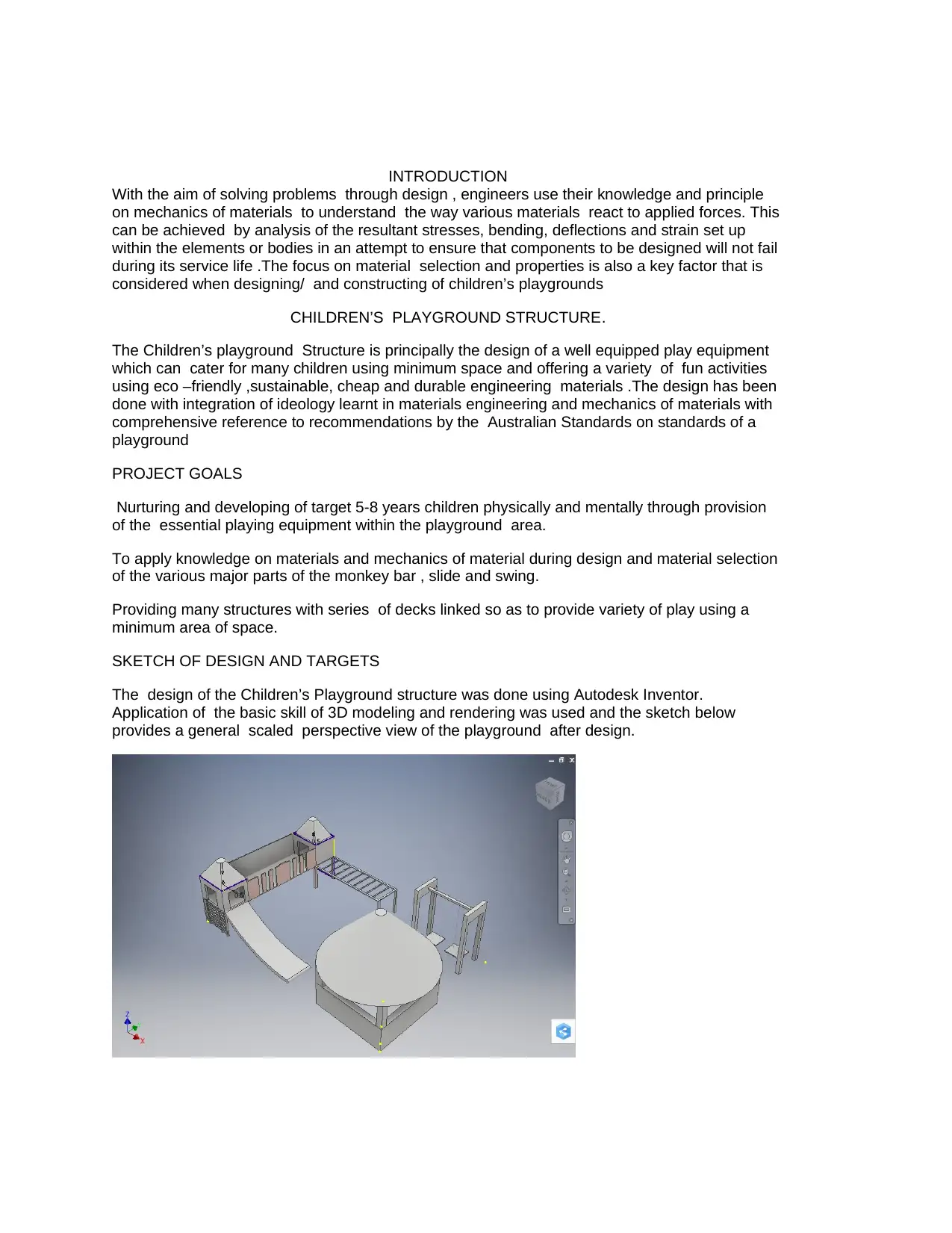
SKETCH OF DESIGN AND TARGETS
The design of the Children’s Playground structure was done using Autodesk Inventor.
Application of the basic skill of 3D modeling and rendering was used and the sketch below
provides a general scaled perspective view of the playground after design.
With the aim of solving problems through design , engineers use their knowledge and principle
on mechanics of materials to understand the way various materials react to applied forces. This
can be achieved by analysis of the resultant stresses, bending, deflections and strain set up
within the elements or bodies in an attempt to ensure that components to be designed will not fail
during its service life .The focus on material selection and properties is also a key factor that is
considered when designing/ and constructing of children’s playgrounds
CHILDREN’S PLAYGROUND STRUCTURE.
The Children’s playground Structure is principally the design of a well equipped play equipment
which can cater for many children using minimum space and offering a variety of fun activities
using eco –friendly ,sustainable, cheap and durable engineering materials .The design has been
done with integration of ideology learnt in materials engineering and mechanics of materials with
comprehensive reference to recommendations by the Australian Standards on standards of a
playground
PROJECT GOALS
Nurturing and developing of target 5-8 years children physically and mentally through provision
of the essential playing equipment within the playground area.
To apply knowledge on materials and mechanics of material during design and material selection
of the various major parts of the monkey bar , slide and swing.
Providing many structures with series of decks linked so as to provide variety of play using a
minimum area of space.
SKETCH OF DESIGN AND TARGETS
The design of the Children’s Playground structure was done using Autodesk Inventor.
Application of the basic skill of 3D modeling and rendering was used and the sketch below
provides a general scaled perspective view of the playground after design.
The design process took into account children aged between 5-8 years putting all the weight
considerations and size of the children into the dimensions of beams ,bars and ropes in a
detailed manner to cover the design shown in the sketch above.
As seen from the sketch the various diverse playing equipment included are :
1. Ladder.
2. Swing.
3. Monkey bar.
4. Tower platform.
5. Bridge.
6. Slide.
7. Recreation shade.
Specifications of the playground structure
1. Height of the tower structure is 1.5m.
2. Area occupied by the playground is 13m x 13m.
3. The length of the monkey bar section is 6 m with 10 climbing bars.
4. The bridge has a length of 4m by a width of 2m.
5. The length of the slide adjacent to the tower platform is 5 m.
6. The height of the cantilever swing from the ground is 0.5 m
7. The recreation shade is a square block with dimensions of 4m by 4m
8. All considerations to tolerance were also taken into account during the design process.
List of Construction Materials
1. Polyester rope for the swing ,
2. Wood, for the tower house.
3. Steel bars for the swing frames
4. Steel slide.
5. Plywood ladder
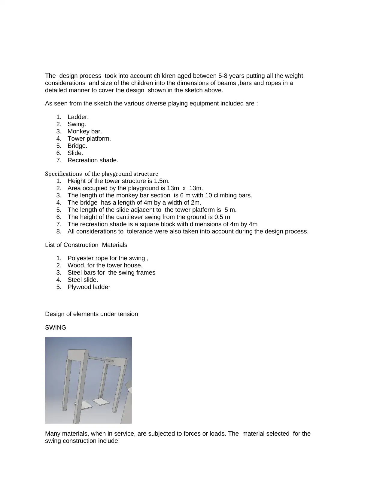
Design of elements under tension
SWING
Many materials, when in service, are subjected to forces or loads. The material selected for the
swing construction include;
considerations and size of the children into the dimensions of beams ,bars and ropes in a
detailed manner to cover the design shown in the sketch above.
As seen from the sketch the various diverse playing equipment included are :
1. Ladder.
2. Swing.
3. Monkey bar.
4. Tower platform.
5. Bridge.
6. Slide.
7. Recreation shade.
Specifications of the playground structure
1. Height of the tower structure is 1.5m.
2. Area occupied by the playground is 13m x 13m.
3. The length of the monkey bar section is 6 m with 10 climbing bars.
4. The bridge has a length of 4m by a width of 2m.
5. The length of the slide adjacent to the tower platform is 5 m.
6. The height of the cantilever swing from the ground is 0.5 m
7. The recreation shade is a square block with dimensions of 4m by 4m
8. All considerations to tolerance were also taken into account during the design process.
List of Construction Materials
1. Polyester rope for the swing ,
2. Wood, for the tower house.
3. Steel bars for the swing frames
4. Steel slide.
5. Plywood ladder
Design of elements under tension
SWING
Many materials, when in service, are subjected to forces or loads. The material selected for the
swing construction include;
1. Poly-supreme rope for the swing rope,
2. Steel seat
3. Steel bars for the frames.
Material Selection.
The seat of a swing is usually suspended from swing set frame on either chains or ropes. Swings
typically apply oscillatory motion and which depends upon air drag which slow it down. The
ropes or wires holding the seat of the swing is usually applied to tensile force when carrying a
load. The load here is the weight of the children and vary depending on the angle of swing . A
cheap ,low carbon footprint ,relatively ductile material was the major factor that singled the
materials into polymer ropes, sisal ropes being selected and capable of considerable distortion
without fracture.
The poly-supreme rope was also selected because of its non-reactive properties therefore they
would be no formation of oxide layers like rust
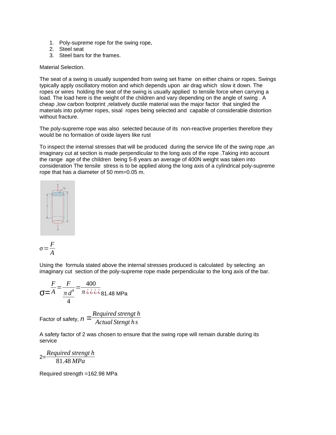
To inspect the internal stresses that will be produced during the service life of the swing rope ,an
imaginary cut at section is made perpendicular to the long axis of the rope .Taking into account
the range age of the children being 5-8 years an average of 400N weight was taken into
consideration The tensile stress is to be applied along the long axis of a cylindrical poly-supreme
rope that has a diameter of 50 mm=0.05 m.
σ = F
A
Using the formula stated above the internal stresses produced is calculated by selecting an
imaginary cut section of the poly-supreme rope made perpendicular to the long axis of the bar.
σ=
F
A = F
π d4
4
= 400
π ¿ ¿ ¿ ¿81.48 MPa
Factor of safety, n =Required strengt h
Actual Stengt h s
A safety factor of 2 was chosen to ensure that the swing rope will remain durable during its
service
2= Required strengt h
81.48 MPa
Required strength =162.98 MPa
2. Steel seat
3. Steel bars for the frames.
Material Selection.
The seat of a swing is usually suspended from swing set frame on either chains or ropes. Swings
typically apply oscillatory motion and which depends upon air drag which slow it down. The
ropes or wires holding the seat of the swing is usually applied to tensile force when carrying a
load. The load here is the weight of the children and vary depending on the angle of swing . A
cheap ,low carbon footprint ,relatively ductile material was the major factor that singled the
materials into polymer ropes, sisal ropes being selected and capable of considerable distortion
without fracture.
The poly-supreme rope was also selected because of its non-reactive properties therefore they
would be no formation of oxide layers like rust
To inspect the internal stresses that will be produced during the service life of the swing rope ,an
imaginary cut at section is made perpendicular to the long axis of the rope .Taking into account
the range age of the children being 5-8 years an average of 400N weight was taken into
consideration The tensile stress is to be applied along the long axis of a cylindrical poly-supreme
rope that has a diameter of 50 mm=0.05 m.
σ = F
A
Using the formula stated above the internal stresses produced is calculated by selecting an
imaginary cut section of the poly-supreme rope made perpendicular to the long axis of the bar.
σ=
F
A = F
π d4
4
= 400
π ¿ ¿ ¿ ¿81.48 MPa
Factor of safety, n =Required strengt h
Actual Stengt h s
A safety factor of 2 was chosen to ensure that the swing rope will remain durable during its
service
2= Required strengt h
81.48 MPa
Required strength =162.98 MPa
Secure Best Marks with AI Grader
Need help grading? Try our AI Grader for instant feedback on your assignments.
It is safe to assume that the stress distribution gradually approaches the uniform distribution at a
distance d away from the ends of the ropes, where d is the largest transverse dimension of the
rope
DESIGN OF ELEMENTS UNDER COMPRESSION
MONKEY BARS
Material selection
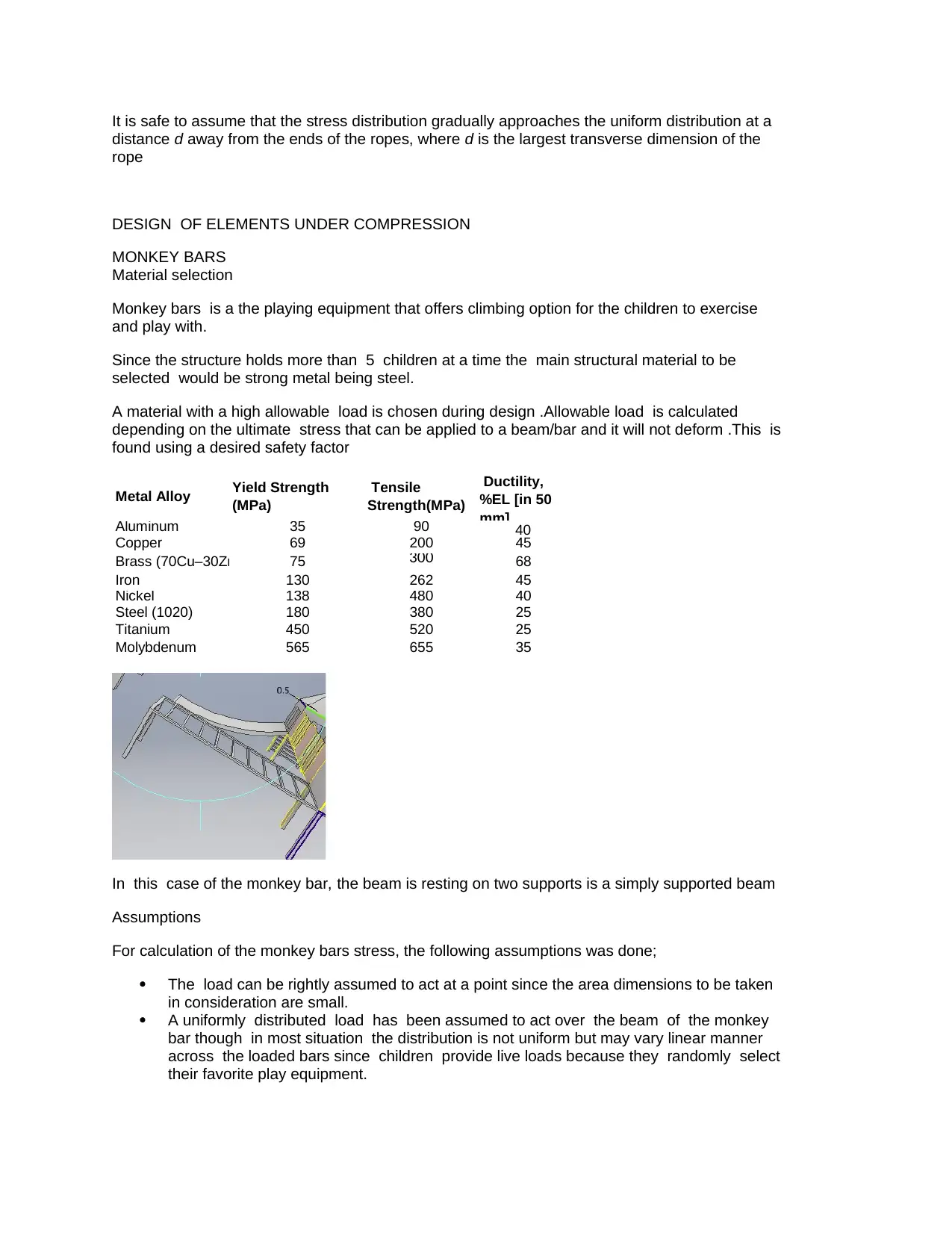
Monkey bars is a the playing equipment that offers climbing option for the children to exercise
and play with.
Since the structure holds more than 5 children at a time the main structural material to be
selected would be strong metal being steel.
A material with a high allowable load is chosen during design .Allowable load is calculated
depending on the ultimate stress that can be applied to a beam/bar and it will not deform .This is
found using a desired safety factor
Metal Alloy Yield Strength
(MPa)
Tensile
Strength(MPa)
Ductility,
%EL [in 50
mm]
Aluminum 35 90 40
Copper 69 200 45
Brass (70Cu–30Zn) 75 300 68
Iron 130 262 45
Nickel 138 480 40
Steel (1020) 180 380 25
Titanium 450 520 25
Molybdenum 565 655 35
In this case of the monkey bar, the beam is resting on two supports is a simply supported beam
Assumptions
For calculation of the monkey bars stress, the following assumptions was done;
The load can be rightly assumed to act at a point since the area dimensions to be taken
in consideration are small.
A uniformly distributed load has been assumed to act over the beam of the monkey
bar though in most situation the distribution is not uniform but may vary linear manner
across the loaded bars since children provide live loads because they randomly select
their favorite play equipment.
distance d away from the ends of the ropes, where d is the largest transverse dimension of the
rope
DESIGN OF ELEMENTS UNDER COMPRESSION
MONKEY BARS
Material selection
Monkey bars is a the playing equipment that offers climbing option for the children to exercise
and play with.
Since the structure holds more than 5 children at a time the main structural material to be
selected would be strong metal being steel.
A material with a high allowable load is chosen during design .Allowable load is calculated
depending on the ultimate stress that can be applied to a beam/bar and it will not deform .This is
found using a desired safety factor
Metal Alloy Yield Strength
(MPa)
Tensile
Strength(MPa)
Ductility,
%EL [in 50
mm]
Aluminum 35 90 40
Copper 69 200 45
Brass (70Cu–30Zn) 75 300 68
Iron 130 262 45
Nickel 138 480 40
Steel (1020) 180 380 25
Titanium 450 520 25
Molybdenum 565 655 35
In this case of the monkey bar, the beam is resting on two supports is a simply supported beam
Assumptions
For calculation of the monkey bars stress, the following assumptions was done;
The load can be rightly assumed to act at a point since the area dimensions to be taken
in consideration are small.
A uniformly distributed load has been assumed to act over the beam of the monkey
bar though in most situation the distribution is not uniform but may vary linear manner
across the loaded bars since children provide live loads because they randomly select
their favorite play equipment.
Calculation of the sum of the forces taken on either side of the beam section with transverse
loads gives the shearing force .Likewise, the bending moment at any section is taken as the
arithmetic sum of the moments of the forces about the section of the beam.
The shearing-force (S.F.) and bending-moment (B.M.) diagrams show the variation of these
quantities along the length of a beam for any fixed loading condition
Using the geometry of the monkey bars and the assumptions taken into account, the reactions
are evaluated in a more simplified manner.
By the symmetry of the beam. Each reaction will therefore take half the applied load,
i.e
RA =RB= 6 x 400 N
2 =1.2 kN
The S.F. at A, using the usual sign convention, is therefore + 1.2 kN.
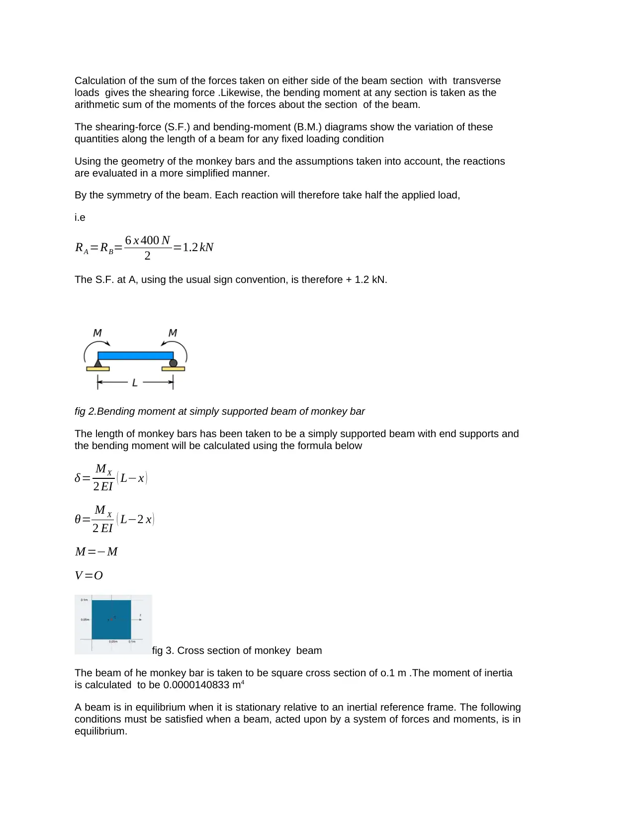
fig 2.Bending moment at simply supported beam of monkey bar
The length of monkey bars has been taken to be a simply supported beam with end supports and
the bending moment will be calculated using the formula below
δ= MX
2 EI ( L−x )
θ= M X
2 EI ( L−2 x )
M =−M
V =O
fig 3. Cross section of monkey beam
The beam of he monkey bar is taken to be square cross section of o.1 m .The moment of inertia
is calculated to be 0.0000140833 m4
A beam is in equilibrium when it is stationary relative to an inertial reference frame. The following
conditions must be satisfied when a beam, acted upon by a system of forces and moments, is in
equilibrium.
loads gives the shearing force .Likewise, the bending moment at any section is taken as the
arithmetic sum of the moments of the forces about the section of the beam.
The shearing-force (S.F.) and bending-moment (B.M.) diagrams show the variation of these
quantities along the length of a beam for any fixed loading condition
Using the geometry of the monkey bars and the assumptions taken into account, the reactions
are evaluated in a more simplified manner.
By the symmetry of the beam. Each reaction will therefore take half the applied load,
i.e
RA =RB= 6 x 400 N
2 =1.2 kN
The S.F. at A, using the usual sign convention, is therefore + 1.2 kN.
fig 2.Bending moment at simply supported beam of monkey bar
The length of monkey bars has been taken to be a simply supported beam with end supports and
the bending moment will be calculated using the formula below
δ= MX
2 EI ( L−x )
θ= M X
2 EI ( L−2 x )
M =−M
V =O
fig 3. Cross section of monkey beam
The beam of he monkey bar is taken to be square cross section of o.1 m .The moment of inertia
is calculated to be 0.0000140833 m4
A beam is in equilibrium when it is stationary relative to an inertial reference frame. The following
conditions must be satisfied when a beam, acted upon by a system of forces and moments, is in
equilibrium.
Σ F X =0 ;
Σ M A =0 :
The sum of the moments about the fixed support at the point A is zero
q1 x 6 x 6
2 + RB x 6=0
ΣM B=0 ;
The sum of the moments about the fixed support at the point B is zero
RA x 6+q1 x 6 x (6− 6
2 )=0
Calculating the reaction of fixed support at the point A
RB=
(q1 x 6 x 6
2 )
6 =
(0.4 x 6 x 6
2 )
6 =1.2 kN
Calculating the reaction of fixed support at the point B
RB=
(q1 x 6 x( 6− 6
2 ))
6 =
(0.4 x 6 x (6−6
2 ))
6 =1.2 kN
The equations for the calculating the shear force (Q) is given as:
Q( X1)=−R A +q1 ( X1−0)
The values of Q at the edges of the span:
Q ( 0 )=1.2−0.4 ( 0−0 ) =−1.2 KN
Q ( 6 )=1 .2−0.4 ( 6−0 )=−1 .2 KN
The value of Q on this span that crosses the horizontal axis. Intersection point:
x = 3
Q ( 6 )=1 .2−0.4 ( 3−0 )=0 KN
The equations for calculating the bending moment (M) across the beam is :
M ( X1 )=−R A ( X1)+q1( X 1
2 )
The values of M at the edges of the span:
M ( X1 ) =1 . 2 ( 0 ) −0.4 ( 02
2 )=0 KNm
M ( X1 )=1 . 2 ( 6 )−0.4 ( 62
2 )=0 KNm
Local extreme at the point x is = 3 :
M ( X1 ) =1 .2 ( 3 ) −0.4 ( 32
2 )=1 .8 KNm
Paraphrase This Document
Need a fresh take? Get an instant paraphrase of this document with our AI Paraphraser
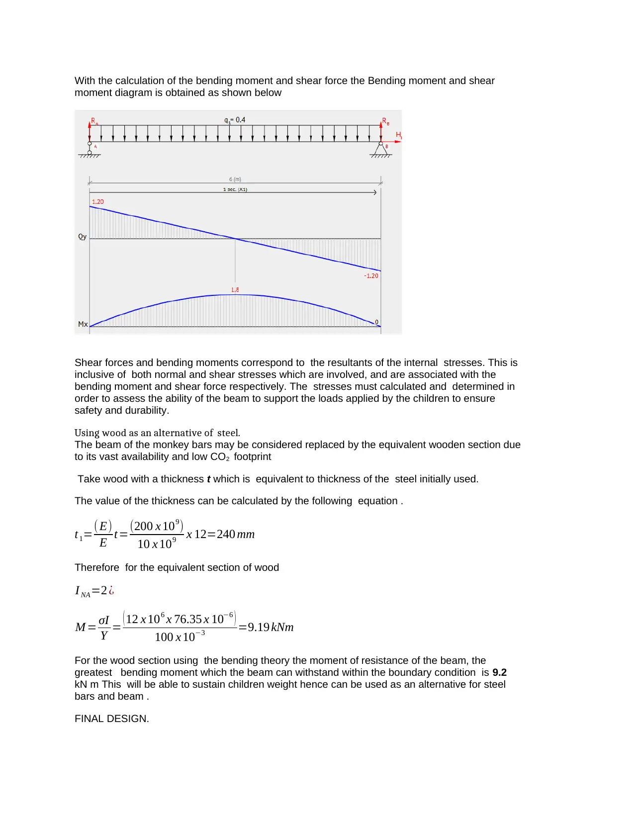
With the calculation of the bending moment and shear force the Bending moment and shear
moment diagram is obtained as shown below
Shear forces and bending moments correspond to the resultants of the internal stresses. This is
inclusive of both normal and shear stresses which are involved, and are associated with the
bending moment and shear force respectively. The stresses must calculated and determined in
order to assess the ability of the beam to support the loads applied by the children to ensure
safety and durability.
Using wood as an alternative of steel.
The beam of the monkey bars may be considered replaced by the equivalent wooden section due
to its vast availability and low CO2 footprint
Take wood with a thickness t which is equivalent to thickness of the steel initially used.
The value of the thickness can be calculated by the following equation .
t1=( E)
E t=(200 x 109)
10 x 109 x 12=240 mm
Therefore for the equivalent section of wood
I NA=2 ¿
M = σI
Y = ( 12 x 106 x 76.35 x 10−6 )
100 x 10−3 =9.19 kNm
For the wood section using the bending theory the moment of resistance of the beam, the
greatest bending moment which the beam can withstand within the boundary condition is 9.2
kN m This will be able to sustain children weight hence can be used as an alternative for steel
bars and beam .
FINAL DESIGN.
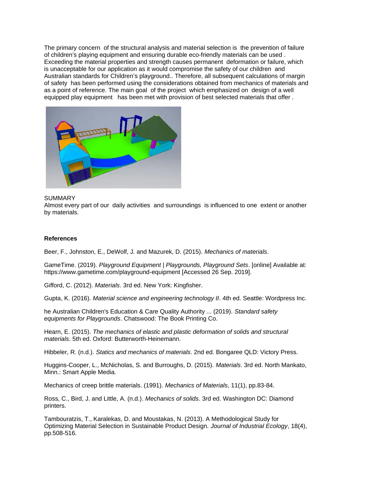
The primary concern of the structural analysis and material selection is the prevention of failure
of children’s playing equipment and ensuring durable eco-friendly materials can be used .
Exceeding the material properties and strength causes permanent deformation or failure, which
is unacceptable for our application as it would compromise the safety of our children and
Australian standards for Children’s playground.. Therefore, all subsequent calculations of margin
of safety has been performed using the considerations obtained from mechanics of materials and
as a point of reference. The main goal of the project which emphasized on design of a well
equipped play equipment has been met with provision of best selected materials that offer .
SUMMARY
Almost every part of our daily activities and surroundings is influenced to one extent or another
by materials.
References
Beer, F., Johnston, E., DeWolf, J. and Mazurek, D. (2015). Mechanics of materials.
GameTime. (2019). Playground Equipment | Playgrounds, Playground Sets. [online] Available at:
https://www.gametime.com/playground-equipment [Accessed 26 Sep. 2019].
Gifford, C. (2012). Materials. 3rd ed. New York: Kingfisher.
Gupta, K. (2016). Material science and engineering technology II. 4th ed. Seattle: Wordpress Inc.
he Australian Children's Education & Care Quality Authority ... (2019). Standard safety
equipments for Playgrounds. Chatswood: The Book Printing Co.
Hearn, E. (2015). The mechanics of elastic and plastic deformation of solids and structural
materials. 5th ed. Oxford: Butterworth-Heinemann.
Hibbeler, R. (n.d.). Statics and mechanics of materials. 2nd ed. Bongaree QLD: Victory Press.
Huggins-Cooper, L., McNicholas, S. and Burroughs, D. (2015). Materials. 3rd ed. North Mankato,
Minn.: Smart Apple Media.
Mechanics of creep brittle materials. (1991). Mechanics of Materials, 11(1), pp.83-84.
Ross, C., Bird, J. and Little, A. (n.d.). Mechanics of solids. 3rd ed. Washington DC: Diamond
printers.
Tambouratzis, T., Karalekas, D. and Moustakas, N. (2013). A Methodological Study for
Optimizing Material Selection in Sustainable Product Design. Journal of Industrial Ecology, 18(4),
pp.508-516.

Zhang, H., Jin, D. and Zhao, X. (n.d.). Advanced research on material science and environmental
science. 4th ed. London: Fast times Co.
science. 4th ed. London: Fast times Co.
1 out of 10
Your All-in-One AI-Powered Toolkit for Academic Success.
+13062052269
info@desklib.com
Available 24*7 on WhatsApp / Email
![[object Object]](/_next/static/media/star-bottom.7253800d.svg)
Unlock your academic potential
© 2024 | Zucol Services PVT LTD | All rights reserved.