Pelton Turbine: Design, Material Selection, Safety & Implementation
VerifiedAdded on 2023/04/22
|7
|2105
|412
Report
AI Summary
This report provides a detailed overview of the design and implementation of a Pelton turbine, focusing on key aspects such as material selection, safety protocols, and build works. It begins by outlining the detailed design of the Pelton runner, emphasizing its reliance on the impulse of moving water. The report then specifies the required materials for various components, including the runner, manifold, nozzle, deflector, turbine shaft, and housing, considering factors like heat resistance, sand content in water, and stress. Design assumptions and rules are discussed, highlighting the importance of minimizing hydraulic, windage, and mechanical losses to maximize turbine efficiency. The report also covers codes and standards for periodic testing, documentation, and maintenance, as well as safety measures to prevent damage from abrasion, erosion, and corrosion. Industry best practices for water power generation are outlined, emphasizing the need to maximize performance while minimizing damage. Finally, the report touches on the budget, implementation, and build works, specifying the use of stainless steel for Pelton turbine runners and nozzles due to its resistance to erosion and cavitation. The design incorporates features such as a distributor pipe to accelerate water flow and a system for circulating oil to dissipate heat from the turbine shaft and bearings. Desklib offers a variety of resources, including similar reports and solved assignments, for students and researchers in the field.

Turbine1
Name
Date
Lecturer
Course
College
Name
Date
Lecturer
Course
College
Paraphrase This Document
Need a fresh take? Get an instant paraphrase of this document with our AI Paraphraser
Turbine2
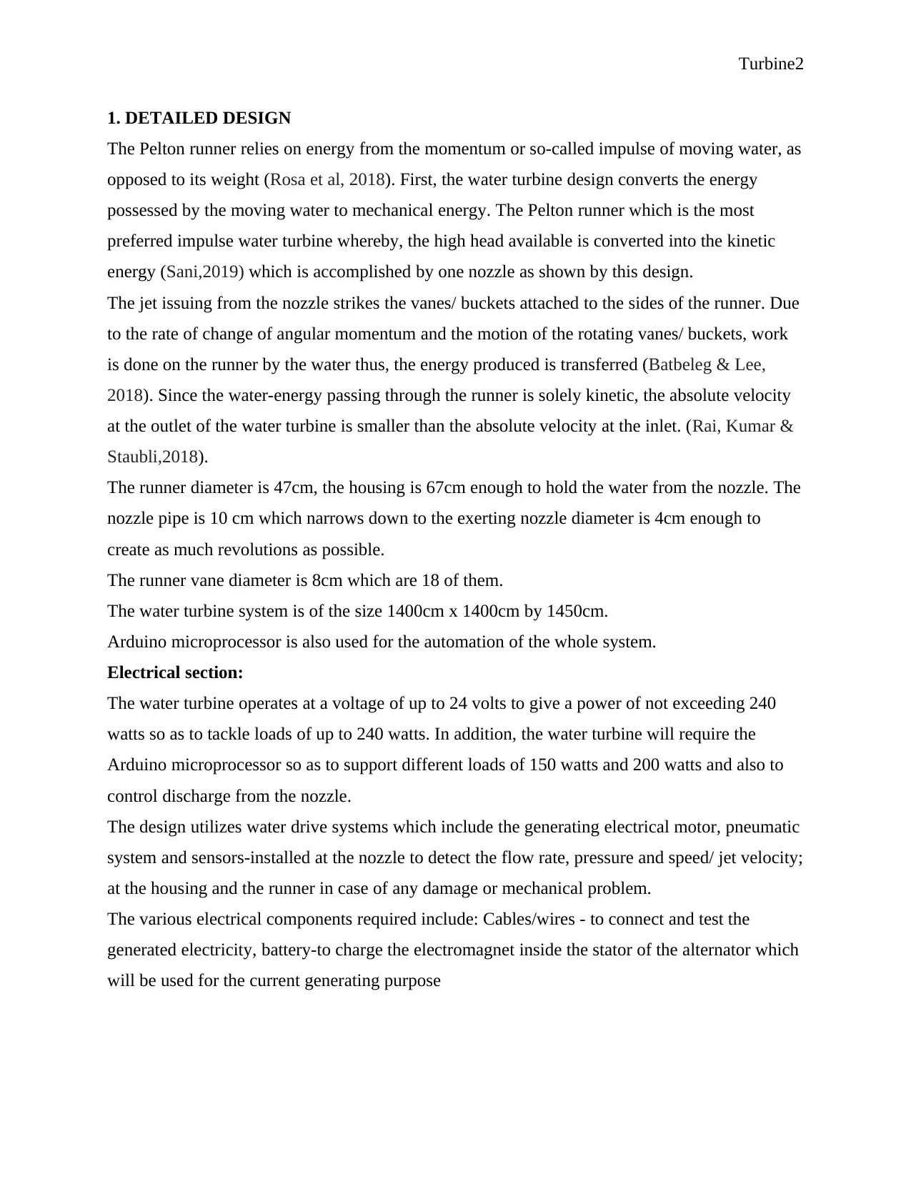
1. DETAILED DESIGN
The Pelton runner relies on energy from the momentum or so-called impulse of moving water, as
opposed to its weight (Rosa et al, 2018). First, the water turbine design converts the energy
possessed by the moving water to mechanical energy. The Pelton runner which is the most
preferred impulse water turbine whereby, the high head available is converted into the kinetic
energy (Sani,2019) which is accomplished by one nozzle as shown by this design.
The jet issuing from the nozzle strikes the vanes/ buckets attached to the sides of the runner. Due
to the rate of change of angular momentum and the motion of the rotating vanes/ buckets, work
is done on the runner by the water thus, the energy produced is transferred (Batbeleg & Lee,
2018). Since the water-energy passing through the runner is solely kinetic, the absolute velocity
at the outlet of the water turbine is smaller than the absolute velocity at the inlet. (Rai, Kumar &
Staubli,2018).
The runner diameter is 47cm, the housing is 67cm enough to hold the water from the nozzle. The
nozzle pipe is 10 cm which narrows down to the exerting nozzle diameter is 4cm enough to
create as much revolutions as possible.
The runner vane diameter is 8cm which are 18 of them.
The water turbine system is of the size 1400cm x 1400cm by 1450cm.
Arduino microprocessor is also used for the automation of the whole system.
Electrical section:
The water turbine operates at a voltage of up to 24 volts to give a power of not exceeding 240
watts so as to tackle loads of up to 240 watts. In addition, the water turbine will require the
Arduino microprocessor so as to support different loads of 150 watts and 200 watts and also to
control discharge from the nozzle.
The design utilizes water drive systems which include the generating electrical motor, pneumatic
system and sensors-installed at the nozzle to detect the flow rate, pressure and speed/ jet velocity;
at the housing and the runner in case of any damage or mechanical problem.
The various electrical components required include: Cables/wires - to connect and test the
generated electricity, battery-to charge the electromagnet inside the stator of the alternator which
will be used for the current generating purpose
Turbine3
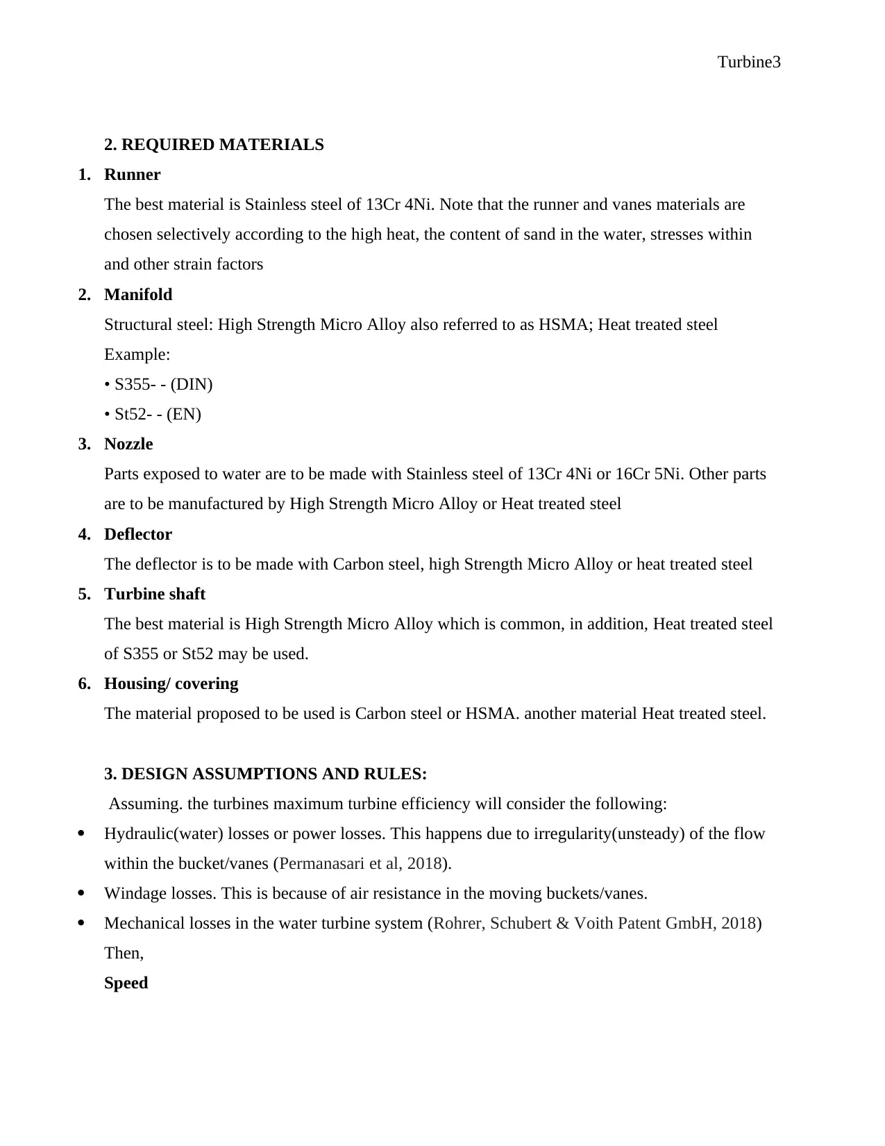
2. REQUIRED MATERIALS
1. Runner
The best material is Stainless steel of 13Cr 4Ni. Note that the runner and vanes materials are
chosen selectively according to the high heat, the content of sand in the water, stresses within
and other strain factors
2. Manifold
Structural steel: High Strength Micro Alloy also referred to as HSMA; Heat treated steel
Example:
• S355- - (DIN)
• St52- - (EN)
3. Nozzle
Parts exposed to water are to be made with Stainless steel of 13Cr 4Ni or 16Cr 5Ni. Other parts
are to be manufactured by High Strength Micro Alloy or Heat treated steel
4. Deflector
The deflector is to be made with Carbon steel, high Strength Micro Alloy or heat treated steel
5. Turbine shaft
The best material is High Strength Micro Alloy which is common, in addition, Heat treated steel
of S355 or St52 may be used.
6. Housing/ covering
The material proposed to be used is Carbon steel or HSMA. another material Heat treated steel.
3. DESIGN ASSUMPTIONS AND RULES:
Assuming. the turbines maximum turbine efficiency will consider the following:
Hydraulic(water) losses or power losses. This happens due to irregularity(unsteady) of the flow
within the bucket/vanes (Permanasari et al, 2018).
Windage losses. This is because of air resistance in the moving buckets/vanes.
Mechanical losses in the water turbine system (Rohrer, Schubert & Voith Patent GmbH, 2018)
Then,
Speed
⊘ This is a preview!⊘
Do you want full access?
Subscribe today to unlock all pages.

Trusted by 1+ million students worldwide
Turbine4
The specific speed is of a turbine directs the turbine's shape which in this case is a Pelton turbine
for the high head.
Energy
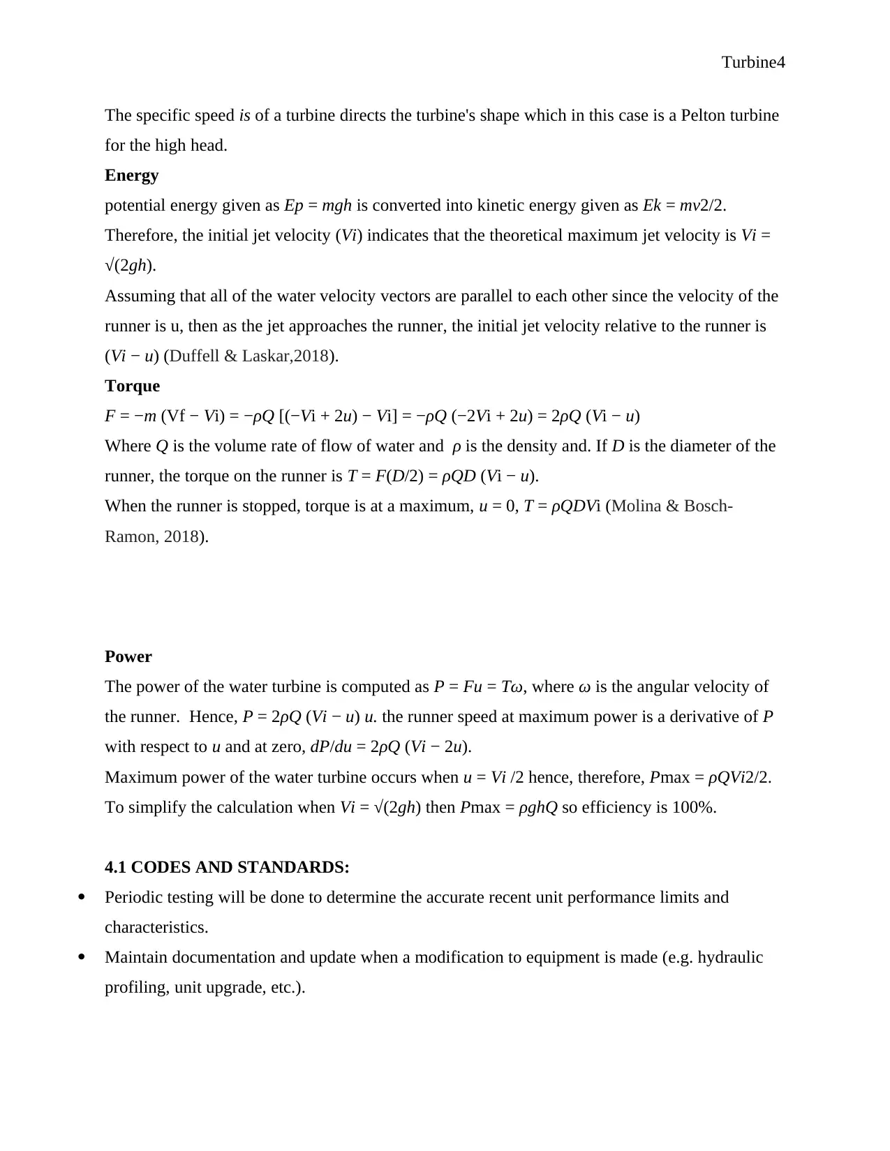
potential energy given as Ep = mgh is converted into kinetic energy given as Ek = mv2/2.
Therefore, the initial jet velocity (Vi) indicates that the theoretical maximum jet velocity is Vi =
√(2gh).
Assuming that all of the water velocity vectors are parallel to each other since the velocity of the
runner is u, then as the jet approaches the runner, the initial jet velocity relative to the runner is
(Vi − u) (Duffell & Laskar,2018).
Torque
F = −m (Vf − Vi) = −ρQ [(−Vi + 2u) − Vi] = −ρQ (−2Vi + 2u) = 2ρQ (Vi − u)
Where Q is the volume rate of flow of water and ρ is the density and. If D is the diameter of the
runner, the torque on the runner is T = F(D/2) = ρQD (Vi − u).
When the runner is stopped, torque is at a maximum, u = 0, T = ρQDVi (Molina & Bosch-
Ramon, 2018).
Power
The power of the water turbine is computed as P = Fu = Tω, where ω is the angular velocity of
the runner. Hence, P = 2ρQ (Vi − u) u. the runner speed at maximum power is a derivative of P
with respect to u and at zero, dP/du = 2ρQ (Vi − 2u).
Maximum power of the water turbine occurs when u = Vi /2 hence, therefore, Pmax = ρQVi2/2.
To simplify the calculation when Vi = √(2gh) then Pmax = ρghQ so efficiency is 100%.
4.1 CODES AND STANDARDS:
Periodic testing will be done to determine the accurate recent unit performance limits and
characteristics.
Maintain documentation and update when a modification to equipment is made (e.g. hydraulic
profiling, unit upgrade, etc.).
Paraphrase This Document
Need a fresh take? Get an instant paraphrase of this document with our AI Paraphraser
Turbine5
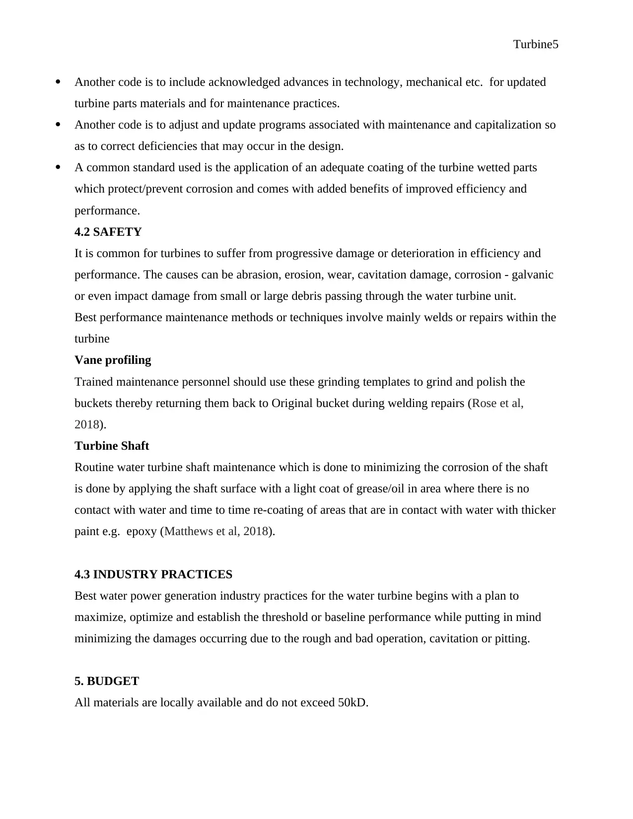
Another code is to include acknowledged advances in technology, mechanical etc. for updated
turbine parts materials and for maintenance practices.
Another code is to adjust and update programs associated with maintenance and capitalization so
as to correct deficiencies that may occur in the design.
A common standard used is the application of an adequate coating of the turbine wetted parts
which protect/prevent corrosion and comes with added benefits of improved efficiency and
performance.
4.2 SAFETY
It is common for turbines to suffer from progressive damage or deterioration in efficiency and
performance. The causes can be abrasion, erosion, wear, cavitation damage, corrosion - galvanic
or even impact damage from small or large debris passing through the water turbine unit.
Best performance maintenance methods or techniques involve mainly welds or repairs within the
turbine
Vane profiling
Trained maintenance personnel should use these grinding templates to grind and polish the
buckets thereby returning them back to Original bucket during welding repairs (Rose et al,
2018).
Turbine Shaft
Routine water turbine shaft maintenance which is done to minimizing the corrosion of the shaft
is done by applying the shaft surface with a light coat of grease/oil in area where there is no
contact with water and time to time re-coating of areas that are in contact with water with thicker
paint e.g. epoxy (Matthews et al, 2018).
4.3 INDUSTRY PRACTICES
Best water power generation industry practices for the water turbine begins with a plan to
maximize, optimize and establish the threshold or baseline performance while putting in mind
minimizing the damages occurring due to the rough and bad operation, cavitation or pitting.
5. BUDGET
All materials are locally available and do not exceed 50kD.
Turbine6
6. IMPLEMENTATION AND BUILD WORKS.
Build works will use stainless steel as the primary material to manufacture Pelton turbine runners
and nozzle. This material is preferred due to its performance properties which include resistance
to erosion, wear, erosion and cavitation) as opposed to other materials which can be inhibitively
expensive.
The shape of the vanes/buckets is primarily for the efficiency of the turbines. However, this will
limit the bucket shape
The runner disc or base is fastened to the water turbine shaft by bolts and nuts of which it is
made of forged steel with an integral flange at both ends.
A hole is drilled at the centre through the whole length of the water turbine shaft with an oil
storage/reservoir attached to the rotating part bolted to the shaft flange.
Journal and thrust bearings will be installed in conjunction with circulating oil which will serve
the purpose of carrying the heat dissipated by the turbine shaft and bearings.
The design also includes a distributor pipe which is designed to provide an acceleration of the
water flow toward the jets.
References
Batbeleg, T. and Lee, Y.H., 2018, July. Numerical prediction of the performance of a micro class
Pelton turbine. In IOP Conference Series: Earth and Environmental Science (Vol. 163, No. 1, p.
012058). IOP Publishing.
Duffell, P.C. and Laskar, T., 2018. On the Deceleration and Spreading of Relativistic Jets. I. Jet
Dynamics. The Astrophysical Journal, 865(2), p.94.
Ehlert, K., Weinberger, R., Pfrommer, C., Pakmor, R. and Springel, V., 2018. Simulations of the
dynamics of magnetized jets and cosmic rays in galaxy clusters. Monthly Notices of the Royal
Astronomical Society, 481(3), pp.2878-2900.
⊘ This is a preview!⊘
Do you want full access?
Subscribe today to unlock all pages.

Trusted by 1+ million students worldwide

Turbine7
Guo, F., Duan, X. and Yuan, Y.F., 2018. Reversing cooling flows with AGN jets: shock waves,
rarefaction waves and trailing outflows. Monthly Notices of the Royal Astronomical
Society, 473(1), pp.1332-1345.
Kim, K. and Choi, D., 2018. Research on the reaction progress of thermodynamic combustion
based on arc and jet plasma energies using experimental and analytical methods. Journal of
Mechanical Science and Technology, 32(4), pp.1869-1878.
Matthews, J.H., Bell, A.R., Blundell, K.M. and Araudo, A.T., 2018. Ultrahigh energy cosmic
rays from shocks in the lobes of powerful radio galaxies. Monthly Notices of the Royal
Astronomical Society, 482(4), pp.4303-4321.
Molina, E. and Bosch-Ramon, V., 2018. Nonthermal emission from high-mass microquasar jets
affected by orbital motion. arXiv preprint arXiv:1808.02260.
Permanasari, A.A., Yaqin, F.F.A., Wulandari, R. and Puspitasari, P., 2018. Experimental
investigation of design parameters for laboratory scale Pelton runner turbine using RSM.
In MATEC Web of Conferences (Vol. 204, p. 07019). EDP Sciences.
Rai, A.K., Kumar, A. and Staubli, T., 2018. Design and verification of a Pelton turbine rig for
hydro-abrasive erosion testing (Doctoral dissertation, IIT Roorkee).
Rohrer, M. and Schubert, T., Voith Patent GmbH, 2018. Runner of a Pelton turbine. U.S. Patent
Application 15/742,596.
Rosa, C.S.D., III, G.B.B.F., Overos, M.D.B. and Sanchez, J., 2018. Design and Development of
a Pico-hydro Pelton Turbine Bucket Using Recycled Polyethylene Terephthalate Bottles.
Rose, C.W., Olley, J.M., Haddadchi, A., Brooks, A.P. and McMahon, J., 2018. An alternative
method for interpreting jet erosion test (JET) data: part 1. Theory. Earth Surface Processes and
Landforms, 43(3), pp.735-742.
Sani, A.E., 2019. Design and Synchronizing of Pelton turbine with centrifugal Pump in RO
Package. Energy.
1 out of 7
Your All-in-One AI-Powered Toolkit for Academic Success.
+13062052269
info@desklib.com
Available 24*7 on WhatsApp / Email
![[object Object]](/_next/static/media/star-bottom.7253800d.svg)
Unlock your academic potential
Copyright © 2020–2025 A2Z Services. All Rights Reserved. Developed and managed by ZUCOL.
