logo

Desklib - ER Diagram, Data Flow Diagram, Pseudo-Code, Level-1 Diagram, Data Dictionary


Added on  2023-06-07

8 Pages1002 Words488 Views
Table of Contents
ER diagram.......................................................................................................................2
Data Flow Diagram...........................................................................................................2
Level-1 diagram.................................................................................................................3
Pseudo-Code for the system...............................................................................................3
Data dictionary..................................................................................................................4
Desklib - ER Diagram, Data Flow Diagram, Pseudo-Code, Level-1 Diagram, Data Dictionary_1
ER diagram
Description -
ERD or Entity rlation diagram is used in software development process to show graphical
representation of different relationships and entities within the software. Apart from core
software development, it helps identifying and depicting relationships within databases in
software development.
Assumptions Explanation:
There is only a single display board which is operated by one user at a time.
Only system board shows the status of the system at any time.
A duct can be used to operate only single CHCSV10 system
A single CHCSV10 can have only one gas meter.
A Gast meter is associated with single CHCSV10 system
A single CHCSV10 can have more than 1 duct but to remain operational more than 50%
ducts should be open
Data Flow Diagram
A data flow diagram (DFD) maps out the flow of information for any process or system. It
uses defined symbols like rectangles, circles and arrows, plus short text labels, to show data
inputs, outputs, storage points and the routes between each destination. Data flowcharts
can range from simple, even hand-drawn process overviews, to in-depth, multi-level DFDs
that dig progressively deeper into how the data is handled. They can be used to analyze an
Desklib - ER Diagram, Data Flow Diagram, Pseudo-Code, Level-1 Diagram, Data Dictionary_2
existing system or model a new one. Like all the best diagrams and charts, a DFD can often
visually “say” things that would be hard to explain in words, and they work for both
technical and nontechnical audiences, from developer to CEO. That’s why DFDs remain so
popular after all these years. While they work well for data flow software and systems, they
are less applicable nowadays to visualizing interactive, real-time or database-oriented
software or systems.
Context diagram
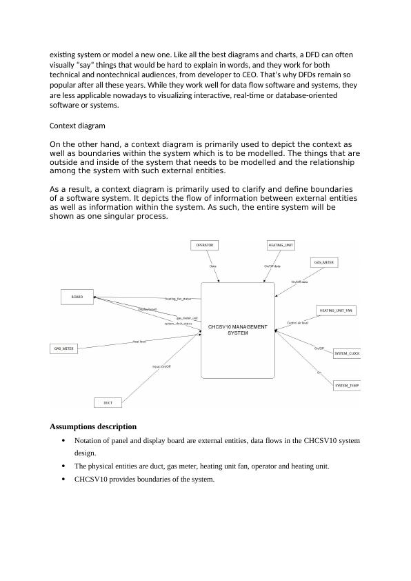
On the other hand, a context diagram is primarily used to depict the context as
well as boundaries within the system which is to be modelled. The things that are
outside and inside of the system that needs to be modelled and the relationship
among the system with such external entities.
As a result, a context diagram is primarily used to clarify and define boundaries
of a software system. It depicts the flow of information between external entities
as well as information within the system. As such, the entire system will be
shown as one singular process.
Assumptions description
Notation of panel and display board are external entities, data flows in the CHCSV10 system
design.
The physical entities are duct, gas meter, heating unit fan, operator and heating unit.
CHCSV10 provides boundaries of the system.
Desklib - ER Diagram, Data Flow Diagram, Pseudo-Code, Level-1 Diagram, Data Dictionary_3

End of preview

Want to access all the pages? Upload your documents or become a member.

Related Documents
Central Heating Control System V10 (CHCSV10) - Entity Relationship Diagram, Data Flow Diagram, Control Flow Diagram, Process Specification, Control Specification
|18
|3351
|481

Software Engineering Method for Real Time Software Modelling
|10
|1760
|497

Software Engineering Methodologies for Real Time Software Modelling: A Case Study of Heat Company's CHCSV10 Project
|9
|1730
|308

Water Heating Software Development using Software Engineering Principles
|15
|1398
|305

Requirements Analysis of Real-Time Central Heating Control System V10
|18
|1318
|191

Software Engineering Methodologies for Heat Company's Central Heating Control V10 Project
|10
|799
|340