System Analysis and Design using UML for Harlow Dental Care Practice
VerifiedAdded on 2023/06/09
|12
|1598
|302
Report
AI Summary
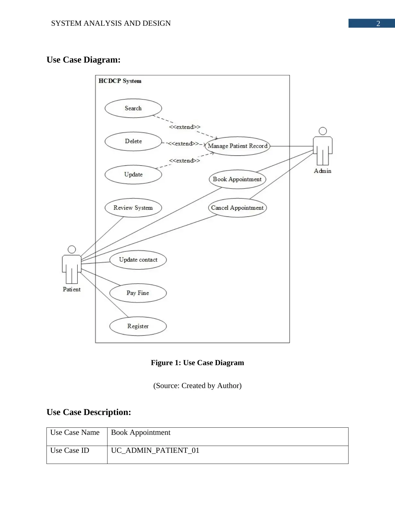
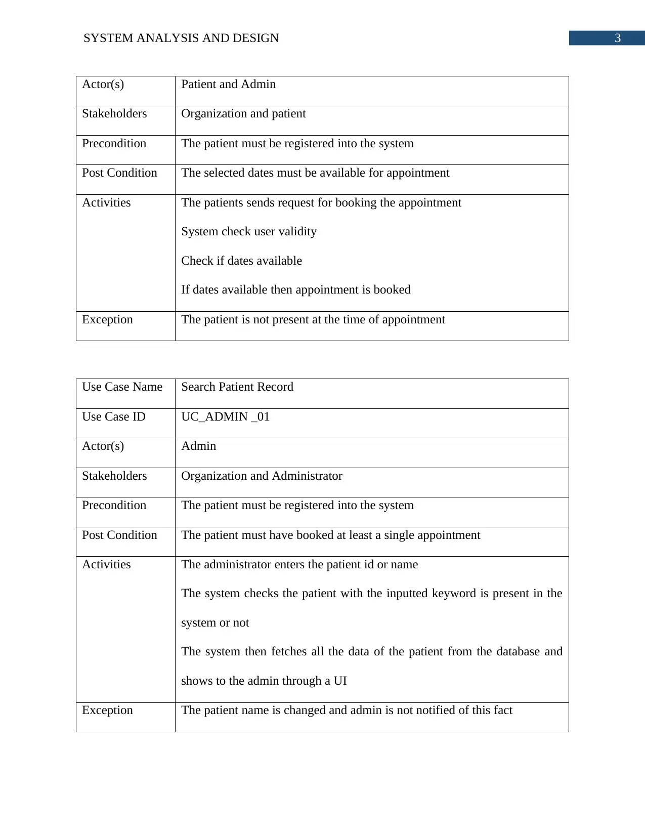
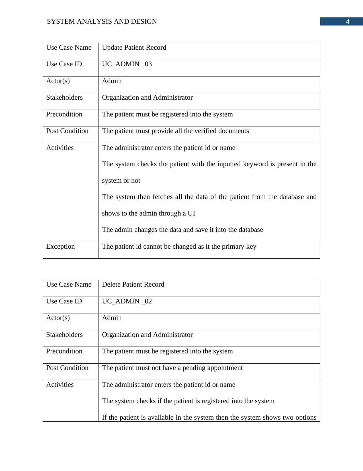
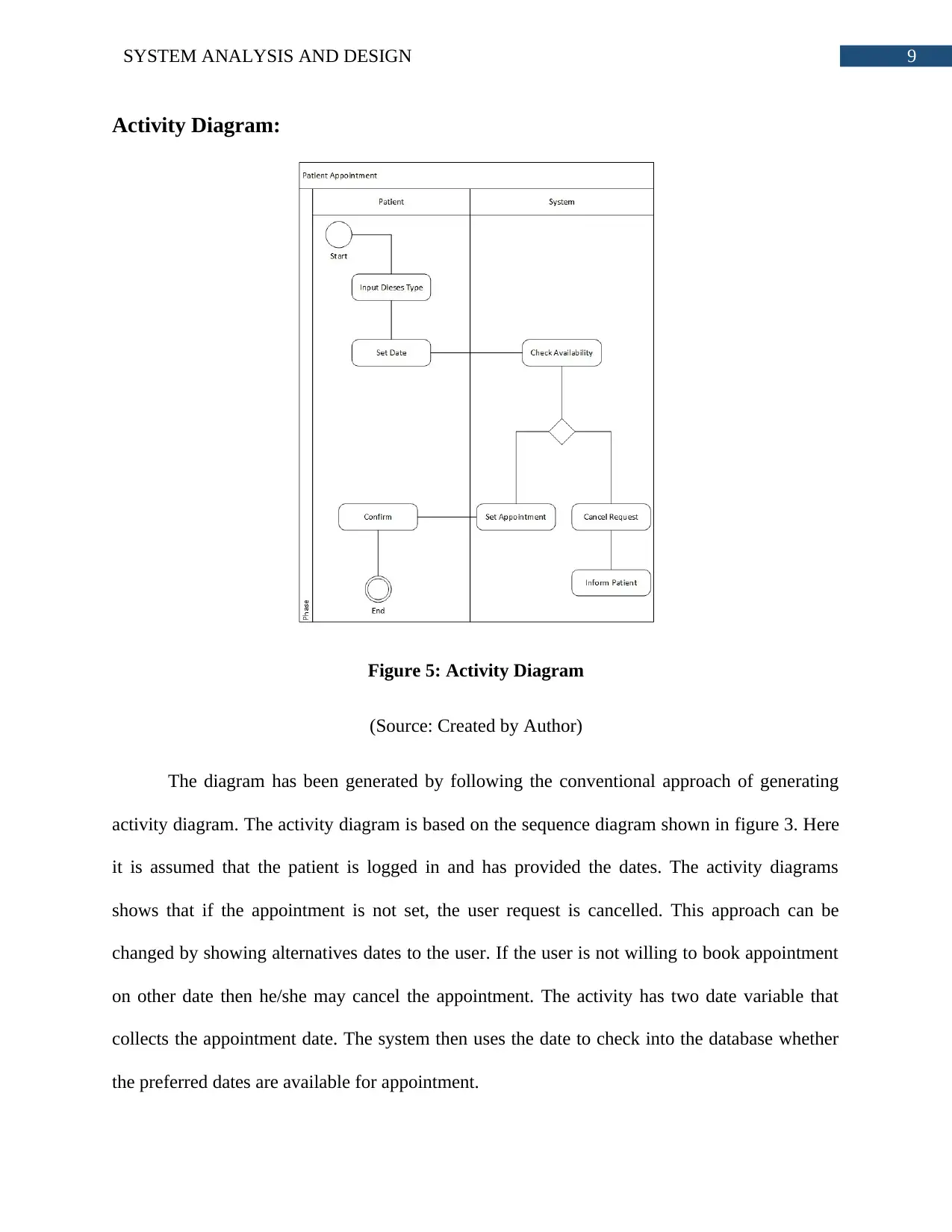
This report presents a system analysis and design for Harlow Central Dental Care Practice, utilizing an object-oriented approach and Unified Modeling Language (UML) diagrams. The analysis includes use case diagrams and descriptions for booking and canceling appointments, searching, updating, and deleting patient records. A class diagram illustrates the system's structure, including classes for patients, appointments, treatments, reviews, and devices. Sequence and activity diagrams detail the appointment scheduling process. The report provides a comprehensive overview of the system's architecture and functionality, designed to meet the needs of the dental practice. Desklib provides a platform for students to access this and similar solved assignments to enhance their understanding.

1 out of 12
Related Documents


Your All-in-One AI-Powered Toolkit for Academic Success.
+13062052269
info@desklib.com
Available 24*7 on WhatsApp / Email
![[object Object]](/_next/static/media/star-bottom.7253800d.svg)
Copyright © 2020–2026 A2Z Services. All Rights Reserved. Developed and managed by ZUCOL.