ProductsLogo
LogoStudy Documents
LogoAI Grader
LogoAI Answer
LogoAI Code Checker
LogoPlagiarism Checker
LogoAI Paraphraser
LogoAI Quiz
LogoAI Detector
PricingBlogAbout Us
logo

Reactor Control System Design

Verified

Added on  2019/09/20

|6
|1729
|362
Essay
AI Summary
The assignment is to design a control software for an Advanced Gas-cooled Reactor (AGR). The software must ensure the reactor's safe operation by controlling temperature, shutdown processes, and secondary shutdown systems. The software will also monitor various safety trip systems, including low gas pressure, control rod motion failed, and danger core temperature. A shutdown command can be initiated in case of an emergency or normal operation. The software should escalate to secondary shutdown if the reactor's temperature does not decrease within a certain timeframe or if the temperature increases. Additionally, the plant should be locked out for 12 hours after an emergency shutdown. The assignment requires students to define data and control context diagrams, data flow diagram (DFD) 0, control flow diagram (CFD) 0, process specifications, control specification, enhanced DFD 0, architecture flow diagram (AFD) 0, and a traceability matrix.

Contribute Materials

Your contribution can guide someone’s learning journey. Share your documents today.
Document Page
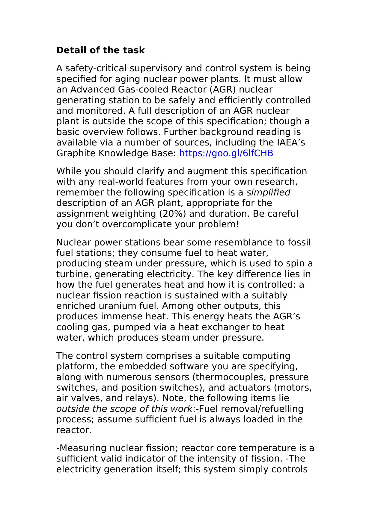
Detail of the task
A safety-critical supervisory and control system is being
specified for aging nuclear power plants. It must allow
an Advanced Gas-cooled Reactor (AGR) nuclear
generating station to be safely and efficiently controlled
and monitored. A full description of an AGR nuclear
plant is outside the scope of this specification; though a
basic overview follows. Further background reading is
available via a number of sources, including the IAEA’s
Graphite Knowledge Base: https://goo.gl/6lfCHB
While you should clarify and augment this specification
with any real-world features from your own research,
remember the following specification is a simplified
description of an AGR plant, appropriate for the
assignment weighting (20%) and duration. Be careful
you don’t overcomplicate your problem!
Nuclear power stations bear some resemblance to fossil
fuel stations; they consume fuel to heat water,
producing steam under pressure, which is used to spin a
turbine, generating electricity. The key difference lies in
how the fuel generates heat and how it is controlled: a
nuclear fission reaction is sustained with a suitably
enriched uranium fuel. Among other outputs, this
produces immense heat. This energy heats the AGR’s
cooling gas, pumped via a heat exchanger to heat
water, which produces steam under pressure.
The control system comprises a suitable computing
platform, the embedded software you are specifying,
along with numerous sensors (thermocouples, pressure
switches, and position switches), and actuators (motors,
air valves, and relays). Note, the following items lie
outside the scope of this work:-Fuel removal/refuelling
process; assume sufficient fuel is always loaded in the
reactor.
-Measuring nuclear fission; reactor core temperature is a
sufficient valid indicator of the intensity of fission. -The
electricity generation itself; this system simply controls

Secure Best Marks with AI Grader

Need help grading? Try our AI Grader for instant feedback on your assignments.
Document Page
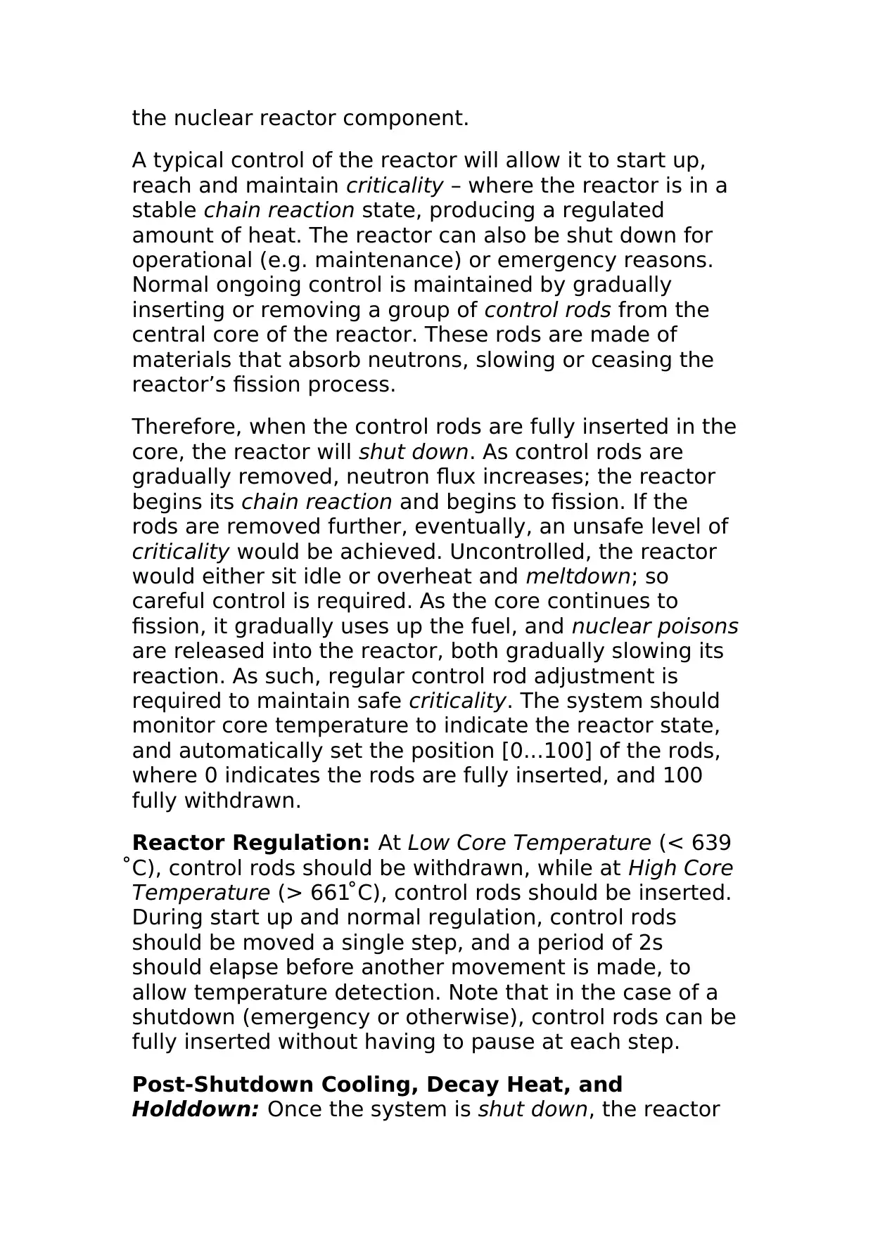
the nuclear reactor component.
A typical control of the reactor will allow it to start up,
reach and maintain criticality – where the reactor is in a
stable chain reaction state, producing a regulated
amount of heat. The reactor can also be shut down for
operational (e.g. maintenance) or emergency reasons.
Normal ongoing control is maintained by gradually
inserting or removing a group of control rods from the
central core of the reactor. These rods are made of
materials that absorb neutrons, slowing or ceasing the
reactor’s fission process.
Therefore, when the control rods are fully inserted in the
core, the reactor will shut down. As control rods are
gradually removed, neutron flux increases; the reactor
begins its chain reaction and begins to fission. If the
rods are removed further, eventually, an unsafe level of
criticality would be achieved. Uncontrolled, the reactor
would either sit idle or overheat and meltdown; so
careful control is required. As the core continues to
fission, it gradually uses up the fuel, and nuclear poisons
are released into the reactor, both gradually slowing its
reaction. As such, regular control rod adjustment is
required to maintain safe criticality. The system should
monitor core temperature to indicate the reactor state,
and automatically set the position [0...100] of the rods,
where 0 indicates the rods are fully inserted, and 100
fully withdrawn.
Reactor Regulation: At Low Core Temperature (< 639 ̊
C), control rods should be withdrawn, while at High Core
Temperature (> 661 ̊ C), control rods should be inserted.
During start up and normal regulation, control rods
should be moved a single step, and a period of 2s
should elapse before another movement is made, to
allow temperature detection. Note that in the case of a
shutdown (emergency or otherwise), control rods can be
fully inserted without having to pause at each step.
Post-Shutdown Cooling, Decay Heat, and
Holddown: Once the system is shut down, the reactor
Document Page
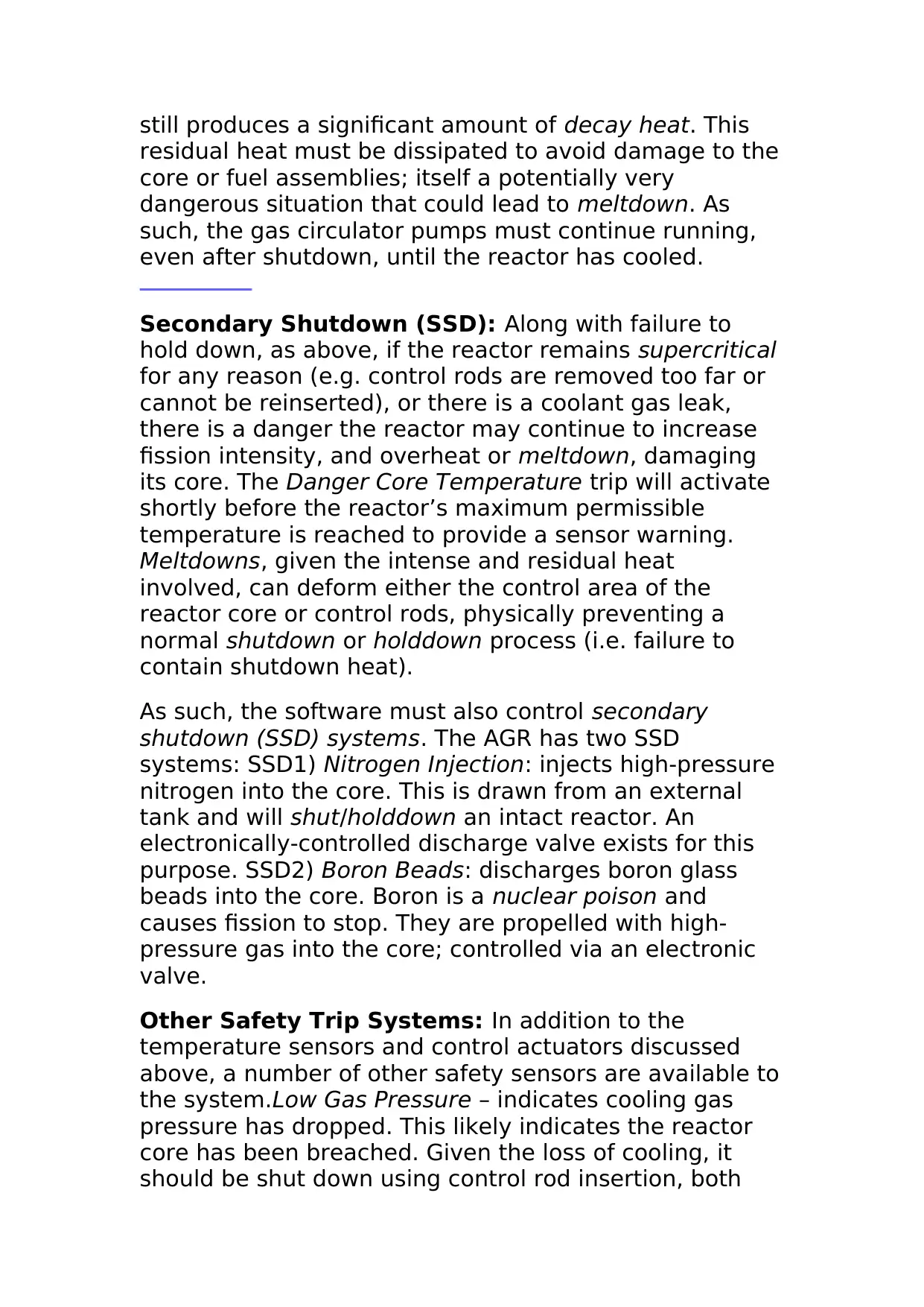
still produces a significant amount of decay heat. This
residual heat must be dissipated to avoid damage to the
core or fuel assemblies; itself a potentially very
dangerous situation that could lead to meltdown. As
such, the gas circulator pumps must continue running,
even after shutdown, until the reactor has cooled.
Secondary Shutdown (SSD): Along with failure to
hold down, as above, if the reactor remains supercritical
for any reason (e.g. control rods are removed too far or
cannot be reinserted), or there is a coolant gas leak,
there is a danger the reactor may continue to increase
fission intensity, and overheat or meltdown, damaging
its core. The Danger Core Temperature trip will activate
shortly before the reactor’s maximum permissible
temperature is reached to provide a sensor warning.
Meltdowns, given the intense and residual heat
involved, can deform either the control area of the
reactor core or control rods, physically preventing a
normal shutdown or holddown process (i.e. failure to
contain shutdown heat).
As such, the software must also control secondary
shutdown (SSD) systems. The AGR has two SSD
systems: SSD1) Nitrogen Injection: injects high-pressure
nitrogen into the core. This is drawn from an external
tank and will shut/holddown an intact reactor. An
electronically-controlled discharge valve exists for this
purpose. SSD2) Boron Beads: discharges boron glass
beads into the core. Boron is a nuclear poison and
causes fission to stop. They are propelled with high-
pressure gas into the core; controlled via an electronic
valve.
Other Safety Trip Systems: In addition to the
temperature sensors and control actuators discussed
above, a number of other safety sensors are available to
the system.Low Gas Pressure – indicates cooling gas
pressure has dropped. This likely indicates the reactor
core has been breached. Given the loss of cooling, it
should be shut down using control rod insertion, both
Document Page
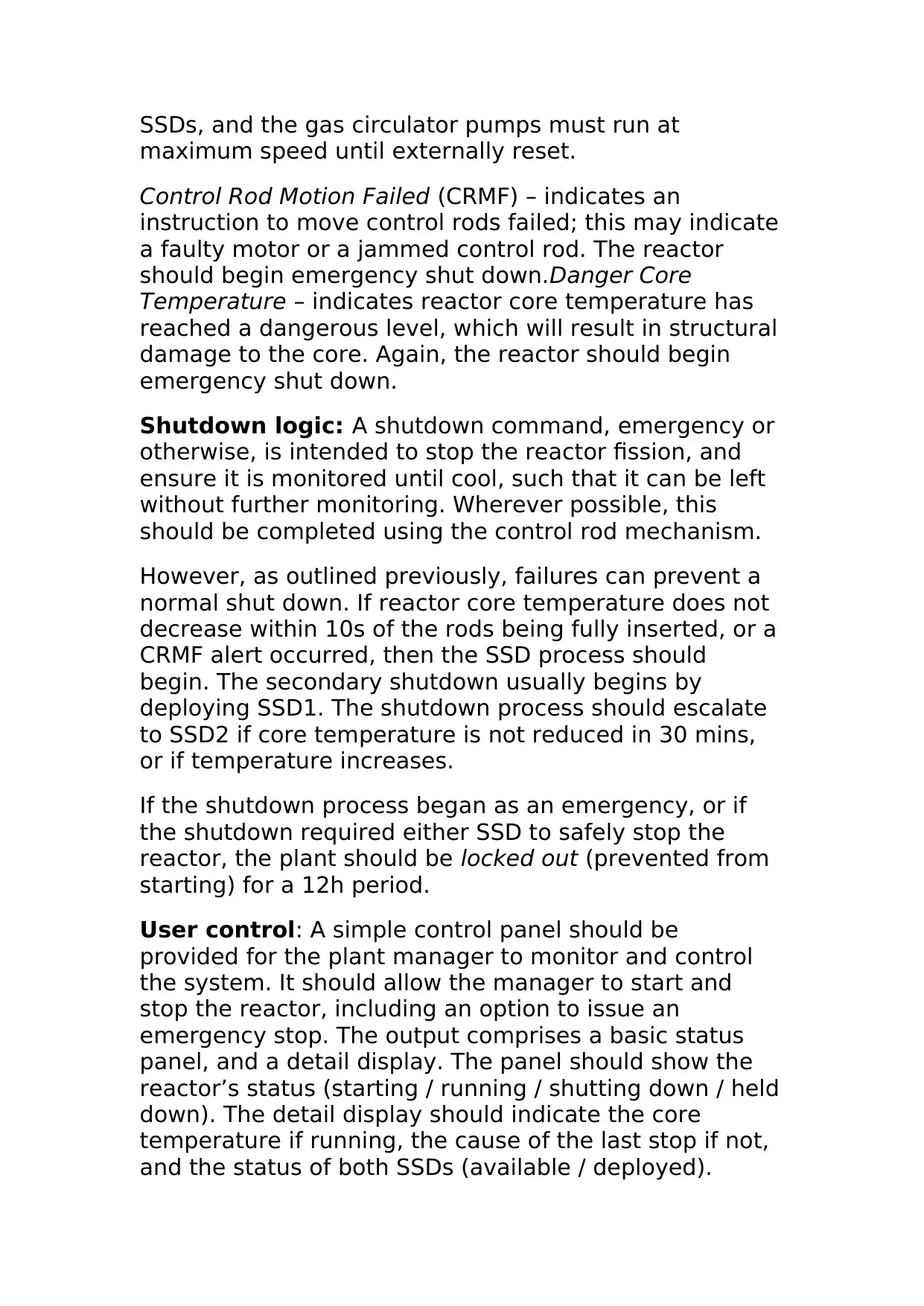
SSDs, and the gas circulator pumps must run at
maximum speed until externally reset.
Control Rod Motion Failed (CRMF) – indicates an
instruction to move control rods failed; this may indicate
a faulty motor or a jammed control rod. The reactor
should begin emergency shut down.Danger Core
Temperature – indicates reactor core temperature has
reached a dangerous level, which will result in structural
damage to the core. Again, the reactor should begin
emergency shut down.
Shutdown logic: A shutdown command, emergency or
otherwise, is intended to stop the reactor fission, and
ensure it is monitored until cool, such that it can be left
without further monitoring. Wherever possible, this
should be completed using the control rod mechanism.
However, as outlined previously, failures can prevent a
normal shut down. If reactor core temperature does not
decrease within 10s of the rods being fully inserted, or a
CRMF alert occurred, then the SSD process should
begin. The secondary shutdown usually begins by
deploying SSD1. The shutdown process should escalate
to SSD2 if core temperature is not reduced in 30 mins,
or if temperature increases.
If the shutdown process began as an emergency, or if
the shutdown required either SSD to safely stop the
reactor, the plant should be locked out (prevented from
starting) for a 12h period.
User control: A simple control panel should be
provided for the plant manager to monitor and control
the system. It should allow the manager to start and
stop the reactor, including an option to issue an
emergency stop. The output comprises a basic status
panel, and a detail display. The panel should show the
reactor’s status (starting / running / shutting down / held
down). The detail display should indicate the core
temperature if running, the cause of the last stop if not,
and the status of both SSDs (available / deployed).

Paraphrase This Document

Need a fresh take? Get an instant paraphrase of this document with our AI Paraphraser
Document Page
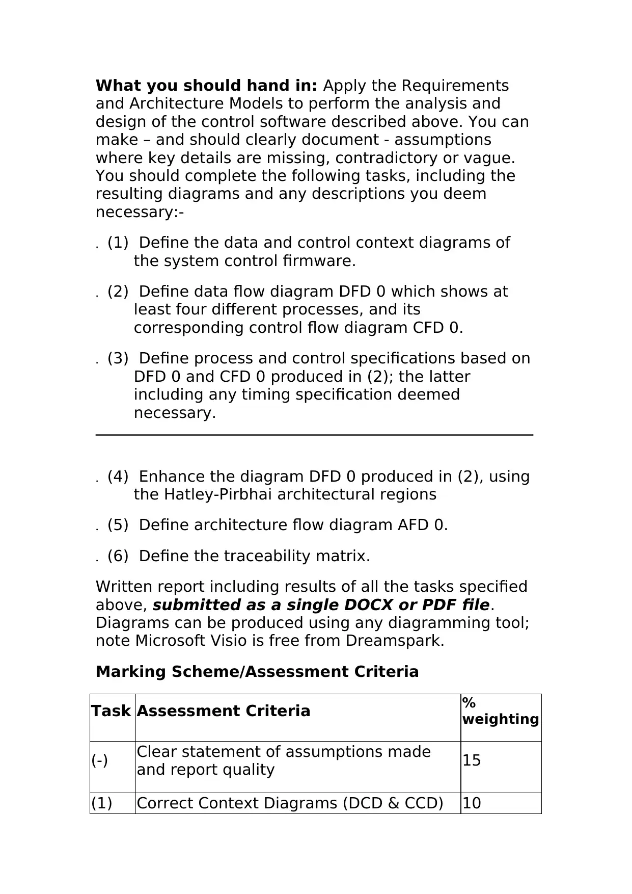
What you should hand in: Apply the Requirements
and Architecture Models to perform the analysis and
design of the control software described above. You can
make – and should clearly document - assumptions
where key details are missing, contradictory or vague.
You should complete the following tasks, including the
resulting diagrams and any descriptions you deem
necessary:-
. (1) Define the data and control context diagrams of
the system control firmware.
. (2) Define data flow diagram DFD 0 which shows at
least four different processes, and its
corresponding control flow diagram CFD 0.
. (3) Define process and control specifications based on
DFD 0 and CFD 0 produced in (2); the latter
including any timing specification deemed
necessary.
. (4) Enhance the diagram DFD 0 produced in (2), using
the Hatley-Pirbhai architectural regions
. (5) Define architecture flow diagram AFD 0.
. (6) Define the traceability matrix.
Written report including results of all the tasks specified
above, submitted as a single DOCX or PDF file.
Diagrams can be produced using any diagramming tool;
note Microsoft Visio is free from Dreamspark.
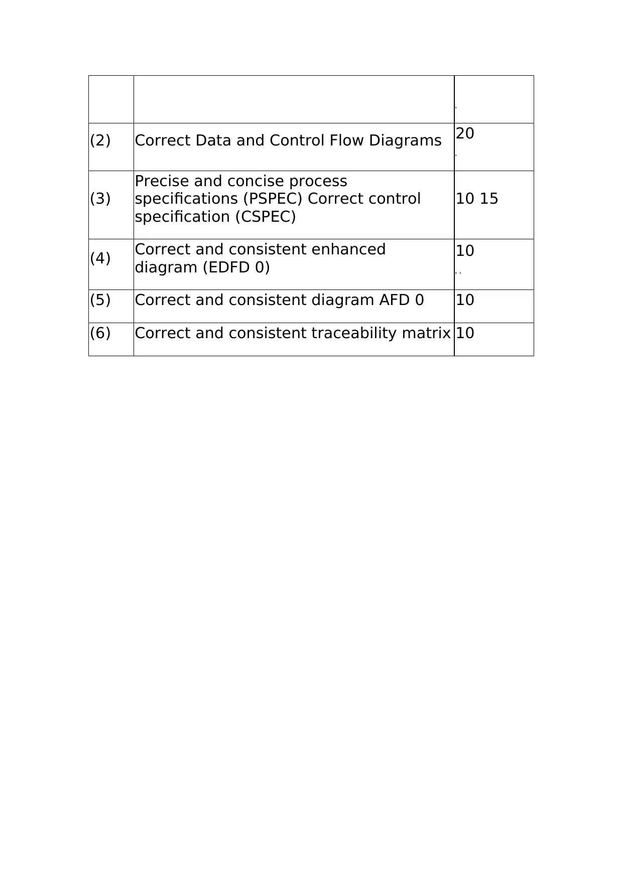
Marking Scheme/Assessment Criteria
Task Assessment Criteria %
weighting
(-) Clear statement of assumptions made
and report quality 15
(1) Correct Context Diagrams (DCD & CCD) 10
Document Page
(2) Correct Data and Control Flow Diagrams 20
(3)
Precise and concise process
specifications (PSPEC) Correct control
specification (CSPEC)
10 15
(4) Correct and consistent enhanced
diagram (EDFD 0)
10
(5) Correct and consistent diagram AFD 0 10
(6) Correct and consistent traceability matrix 10
1 out of 6
[object Object]

Your All-in-One AI-Powered Toolkit for Academic Success.

Available 24*7 on WhatsApp / Email

[object Object]