Deterioration of RC Bridge Beam Deck: What Went Wrong in

Verified

Added on  2022/11/23

|74
|16003
|1
AI Summary
The topic name is: Localize Deterioration of RC Bridge Beam: What Went Wrong Or: Deterioration of RC Bridge Beam Deck: What Went Wrong the topic is a case study on 3 bridges in Malaysia- Taiping different laboratory tests and sight test has been conducted I prefer that the writing focus less on the carbonation. I will link a google drive file for the tests and results photos to be used in the writing. https://drive.google.com/drive/folders/1u5vK64XQhovDY-jc7rJNhdDxjkU7H7iu?usp=sharing

Contribute Materials

Your contribution can guide someone’s learning journey. Share your documents today.
Document Page
Deterioration of RC Bridge Beam Deck: What Went Wrong in Malaysia
Student Name
Subject Name
Date

Secure Best Marks with AI Grader

Need help grading? Try our AI Grader for instant feedback on your assignments.
Document Page
Table of Contents
Executive Summary....................................................................................................................................4
Chapter 1: Introduction...............................................................................................................................5
Research Questions.................................................................................................................................6
Problem Statement..................................................................................................................................6
Objectives of Study.................................................................................................................................7
Main Objective...................................................................................................................................7
Specific Objectives.............................................................................................................................7
Scope......................................................................................................................................................8
Chapter 2: Literature Review......................................................................................................................8
Concrete Microstructure Analysis...........................................................................................................8
Cement paste.......................................................................................................................................8
Pore Structure...................................................................................................................................11
Interfacial Transition Zone................................................................................................................12
Microstructure of High Performance Concrete.................................................................................16
Effect of Microstructure on Strength as well as the Durability.........................................................18
Carbonation......................................................................................................................................21
Principle of Deterioration.....................................................................................................................22
External Attack.................................................................................................................................22
Internal Attack..................................................................................................................................23
Bridge Evaluation Using Nondestructive Testing.................................................................................24
Rebound Hammer Test.........................................................................................................................26
Problems in Concrete Members............................................................................................................29
Load Induced Crack..............................................................................................................................30
Corrosion Induced................................................................................................................................33
Chapter 3: Material and Methods..............................................................................................................35
Rebound Hammer Procedure................................................................................................................35
Procedure for Schmidt Rebound Hammer Test.................................................................................35
Chapter 4: Case Study...............................................................................................................................37
Site Location.........................................................................................................................................37
Visual Inspection..................................................................................................................................38
Detailed Design of Bridge....................................................................................................................39
Sampling and pH Testing......................................................................................................................40
Defect Mapping of all three Bridges.....................................................................................................41
Assessment...........................................................................................................................................43
Chapter 5: Results and Discussion............................................................................................................44
Non-Destructive Test (NDT) on Rebound Hammer.............................................................................44
Document Page
Data for Temperature and Relative Humidity.......................................................................................46
Quantitative Results for Test (3322).....................................................................................................48
Sound Test............................................................................................................................................49
Elements and Standard Concentration..................................................................................................50
Concrete Structure Analysis..................................................................................................................54
Concrete Microstructure.......................................................................................................................56
XRD Testing.........................................................................................................................................59
Environmental Testing-Soil SEM/EDX Testing (Soil)-Sg. Cheh.........................................................60
Soil Microstructure...........................................................................................................................61
Soil CHN-S Test...............................................................................................................................64
Soil pH Test......................................................................................................................................64
Carbonation Test...............................................................................................................................65
Chapter 6: Conclusion and Recommendation...........................................................................................67
References................................................................................................................................................68
Document Page
Executive Summary
There are various complexes imbued as well as uncertainty which are largely associated with the
condition assessment of the makeable reinforced concrete bridges in Malaysia. This complexity
mainly considered to have developed from a number of problems. In essence, there are a number
of factors which are considered to have in-depth impacts on the conditions of the parametric
bridges. Thus, the condition assessment of the bridge network requires vast knowledge and
understanding of the different factors. These factors must be appraised in line with the structural
behaviors of the various concrete structures. Some of the structures often subjected to makeable
phenomena such as environmental effects, excessive loading as well as chemical attacks. The
evaluation can therefore be attained via the application of the comprehensive and knowledge-
based system. In the recent analysis, there is the using of the Public Works Department also
abbreviated as (JKR). The nature of the assessment associated with the Public Works
Department or (JKR) largely termed as the visual inspection. However, current comprehensive
system often requires the inclusion of both the visual inspection and the using of the non-
destructive tests. In addition to this, one can also use the distress investigation to examine the
structural failures in line with the bridges as well. This paper therefore discusses three case
studies of bridges in the Malaysia. The bridges discussed in this paper include Jalan Bendang
Siam, Senduk Hulu and Cheng. Further to this, there is also the documentation of the findings as
well as the drawing of the conclusions and recommendations from the study.

Secure Best Marks with AI Grader

Need help grading? Try our AI Grader for instant feedback on your assignments.
Document Page
Chapter 1: Introduction
In Malaysia, the Public Works Department is regarded as the legal entity and custodian of the
more than 7000 bridges existing in the federal state. In addition to this, it is estimated that
number of bridges which are made up of the concrete sum up-to 70% of the overall bridges
existing in the country. Further to this, it is important to deduce that at least 250 bridges existing
in the country were built at the makeable beginning of the 1960s. Also, there are about 1000
bridges which were built between 1978 and 1979 and this alone has attained the estimate age of
40 years old. Preferably, 40 years is estimated and deduce as the mid-life span and age for any
typical bridge. Thus, at this level it is important to conduct the overall inspections and evaluation
with the aim of conduction rehabilitations required for the aspect. On the other hand, 75 years is
the overall useful and typical life span of the bridge. Therefore, most of the bridges in Malaysia
have attained the midlife span with some even exceeding the set limit and thus, it will be
important to conduct the deterioration and corrosion analysis of the bridges to attain the
suitability of the bridges. The assessment also aims at establishing the safety levels of these
bridges as well as the recommendations which one should consider as far as the failures in the
bridges is concerned [1].
There are various problems which are associated with the RC bridge in different countries. For
instance, the bridge failures in Malaysia primarily anticipated with the various terms such as the
distress, deteriorations, damages as well as bridge failures. The failures associated with the RC
bridges are often increasing in different countries. The past studies have reported that different
failures have been depicted in various states and countries and this cannot be overruled at all
costs. In the recent days, it is evidential that the activities in line with the evaluation and the
inspection of the bridges are quite complex and difficult to carry out as opposed to the
construction and the designing of new bridges. This process not only requires keenness but also
in-depth understanding for one to be able to notice the faults while at the same time making
sound engineering judgments. The judgment in lien with the visual inspection is not only
important for the maintenance but also for ensuring that the structure is safe over its lifetime. On
the other hand, all the calculations involve should be conducted while giving the allowances to
Document Page
both the corroded sections as well as the existing faults in the bridges. Notably, it is important to
recommend that most of the old bridges were largely designed and built using the earlier codes
of practice and loadings. Fortunately, there was the incorporation of the high safety factors and
these codes in the designing of such bridges. Logically, it is important to incorporate the design
codes and safety factors when dealing the modern loading but this will require the reassessing of
the suitability and strength of the existing as well as future traffic [2].
Research Questions
Also, it is important to note that the inspection of the bridges tends to answer the following
research questions
What is the overall condition of the bridge is it sound or not?
Does the bridge behavior comply with the intensions of the designer in line with the
structural conformance?
What is the maximum load which these bridges can accommodate in line with the
safety value without causing or leading to any weakening?
What is the level of the corrosion and deterioration which one can report from the
assessment?
What is the strengthening program which one needs to allow the overall bridges to
carry in line with the present as well as future related traffic loadings?
Is the value established in line with the level of the corrosion and deterioration of the
bridges economical or requites maintenance?
Problem Statement
Considerably, it is essential to anticipate that bridges as well as other structures tend to
deteriorate and this is grounded on the use and time. Often than not, there are different factors
which contributes to the deterioration of the bridges and they include traffic, rain, thaw cycles,
climate, pollution, freeze, moisture variation and temperature. This deterioration problem can
lead to various impacts on the bridge such as causing failures of the bridge. Thus, it is important
to conduct periodic bridge assessment and inspection to curb this problem. The assessment of
Document Page
the bridge should focus on the implications, extension as well as the current deterioration state
and process. Other importance of conducting the inspection process is that it will help in
preventing the failures while at the same time assisting in giving the information which are often
necessary in coming up with the effective bridge network administration. During the inspection
process, it will necessary and fundamentally important to ascertain the various elements which
require urgent repairs, replacement and maintenance action. Also, these analogies can be
reported as far as the evaluation is concerned[3]. Thus, grounded on the established report the
administrative bodies will be in the position to explore and apply the gathered information in
establishing the programs as well as defining the priorities. There are two key aspects which one
can use when gathering the information as well as when exploring the bridges. These include
structural analysis as well as visual inspection. However, there is increase application of the
visual inspection in the present days. However, when the visual method is applied to conduct the
evaluation of the bridges, then it will be important to have a subjective rating. The subjective
rating should be assigned to the makeable bridge components by the decisive and responsible
inspector. In addition to this, the condition rating used in the process largely regarded as the
defined primary sets as well as qualitative analogy in line with the visual indicators. This is
largely used in the routine checking [4].
Objectives of Study
The objectives for this project often divided into two key subsections which include main
objective and specific objectives as discussed below
Main Objective
To assess the deterioration of RC Bridge Beam Deck: What Went Wrong in Malaysia
Specific Objectives
To explore three case study in line with the Deterioration of RC Bridge Beam Deck: What
Went Wrong in Malaysia
To explore the various tests and methods which are used to establish the Deterioration of RC
Bridge Beam Deck: What Went Wrong in Malaysia
To assess the recommendations for the problems

Paraphrase This Document

Need a fresh take? Get an instant paraphrase of this document with our AI Paraphraser
Document Page
Scope
The research encompasses on the study of the three bridges which include Jambatan Sungai
Gantang, Hulu as well as Cheg. The bridges largely examined in lien with the RC deteriorations
in the Malaysia state. Thereafter, various recommendations and conclusion were drawn from the
three case studies.
Chapter 2: Literature Review
Concrete Microstructure Analysis
Concrete microstructure has three major components; they include inter-facial change region
between a cement paste as well as the aggregates, Pore structure as well as the cement paste. It is
important to note that the concrete microstructure is a heterogeneous in nature. Therefore, the
three components must be upgraded in order to achieve a strong durability as far as the concrete
is concerned as well as the improved strength mechanically[5].
Cement paste
The cement is mainly made up of alumina and silica largely abbreviated as (Al203) and (Si02)
respectively, iron oxide as well as the lime mostly abbreviated as (Fe2O3) and (CaO). The
ordinary Portland cement is made up of components such as the di-calcium silicate, tetra-
calcium alumi-noferrite, tri-calcium silicate as well as the tri-calcium aluminate. They mostly
abbreviated as (C2S), (C4AF), (C3S), (C3A) respectively. The hydrated cement paste
microstructure is made up of different phases, and they include calcium hydroxide, cement
particles, ettringite, calcium silicate, air voids as well as the unhydrated. The concrete is mixture
of the ordinary portal and cement as well as the water and the aggregate. To achieve desirable
end products as far as the concrete is concerned majorly during the practical , it is advisable to
add the additives together with different size particles as well as the specific surface zones into
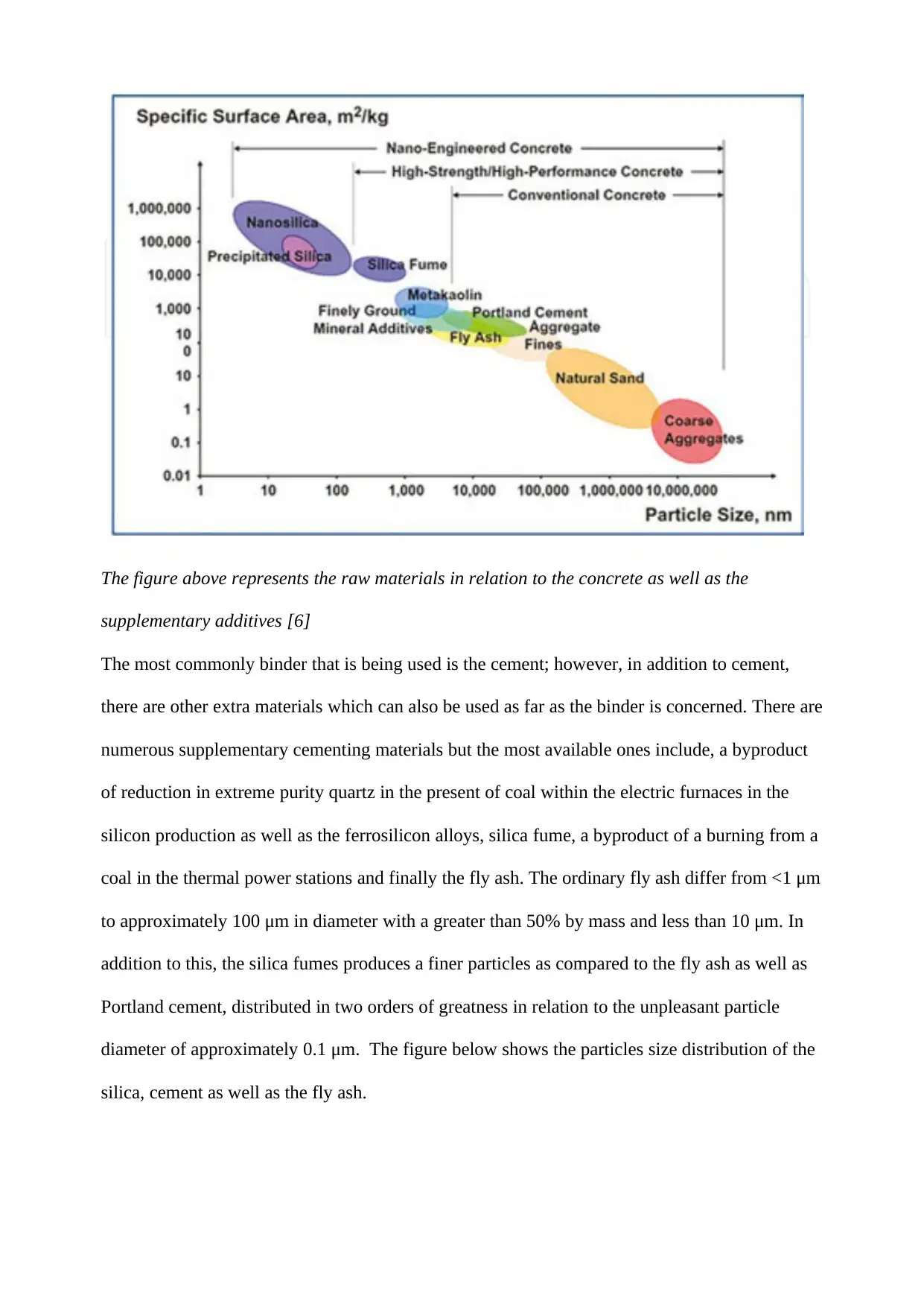
the raw materials. The following diagram shows the materials specifically the raw ones of
concrete as well as the supplementary condiments in relation to the particle size as well as the
specific surface zones.
Document Page
The figure above represents the raw materials in relation to the concrete as well as the
supplementary additives [6]
The most commonly binder that is being used is the cement; however, in addition to cement,
there are other extra materials which can also be used as far as the binder is concerned. There are
numerous supplementary cementing materials but the most available ones include, a byproduct
of reduction in extreme purity quartz in the present of coal within the electric furnaces in the
silicon production as well as the ferrosilicon alloys, silica fume, a byproduct of a burning from a
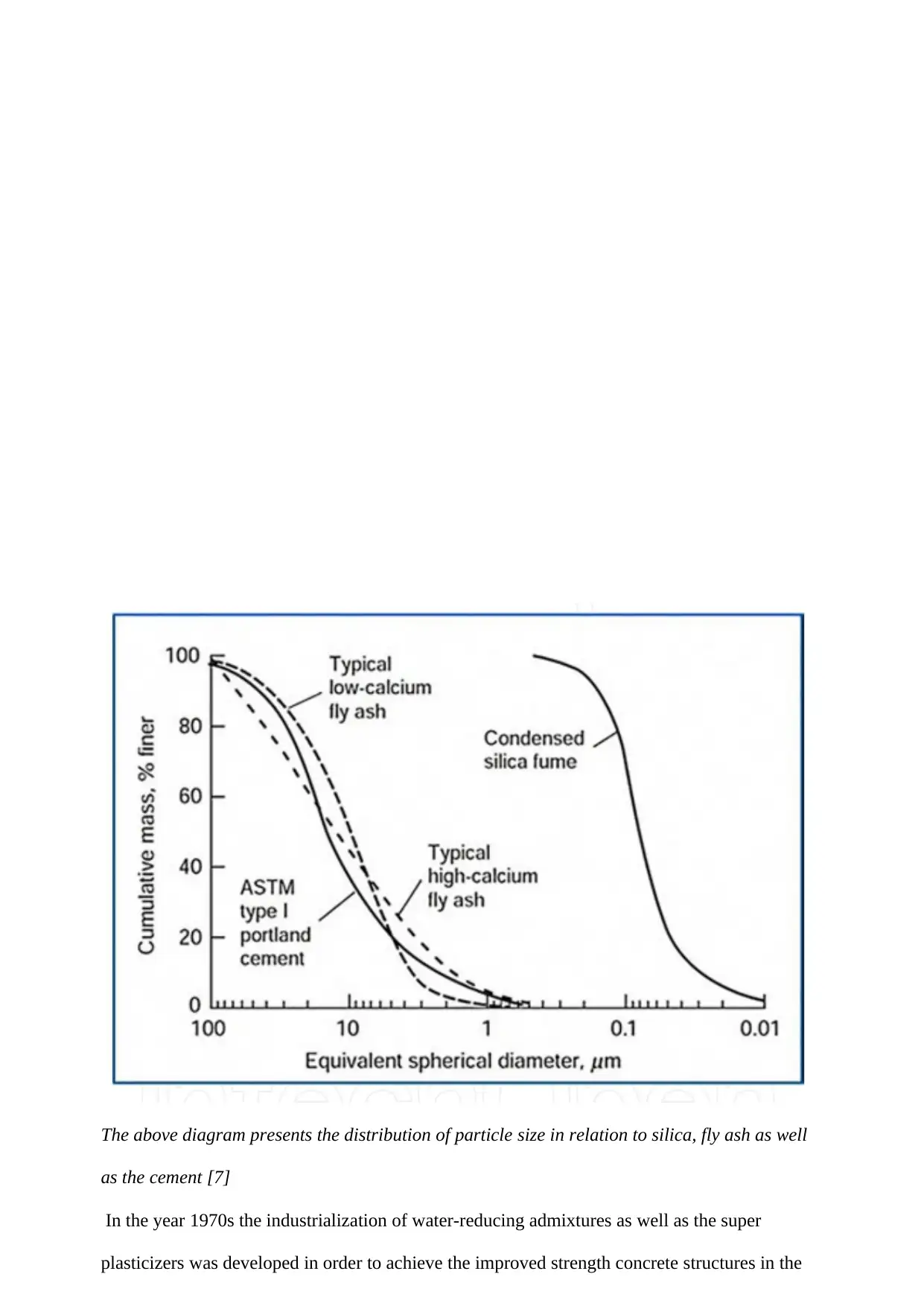
coal in the thermal power stations and finally the fly ash. The ordinary fly ash differ from <1 μm
to approximately 100 μm in diameter with a greater than 50% by mass and less than 10 μm. In
addition to this, the silica fumes produces a finer particles as compared to the fly ash as well as
Portland cement, distributed in two orders of greatness in relation to the unpleasant particle
diameter of approximately 0.1 μm. The figure below shows the particles size distribution of the
silica, cement as well as the fly ash.
Document Page
The above diagram presents the distribution of particle size in relation to silica, fly ash as well
as the cement [7]
In the year 1970s the industrialization of water-reducing admixtures as well as the super
plasticizers was developed in order to achieve the improved strength concrete structures in the

Secure Best Marks with AI Grader

Need help grading? Try our AI Grader for instant feedback on your assignments.
Document Page
construction industry. This new development was accepted around the world due to its
strengthening ability to the concrete structures. The surfactant conveys a very strong and
negative charge in the event that is absorbed in the presence of the cement particles. When this
happens, the end result lowers surface pressure within the surrounding water hence the
improvement in the system fluidity. When the particles of cements which contains a mixture of
both the negative as well as the positive charges are completely mixed with the water, They both
merge into the flocks and instead form a trap of a substantially volume of a mixing water which
in return reduces the fluidity. This process can be corrected by adding the supper plasticizer
which entirely consists of the negative ionic particles. The function of this is to primarily form a
negative charge within the cement particles after thoroughly adsorbing into the solution. It is
from this point that the cement particles repel against each one of them, hence becoming more
and more dispersed. They therefore become open for the trapped waters to leave as well as the
increase in the fluidity. The diagram bellow represents a complete plasticizers ‘action.
The above figure shows a plasticizer’s action [8]
Pore Structure
The pore structure of a cementitious material is well recognized due to its influence majorly on
the concrete durability as well as its strength. It is important to note that, the pore structures are
effect due to their permeability, pore size circulation as well as the material porosity
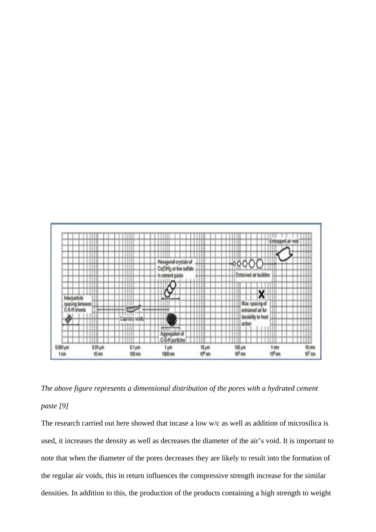
characteristics. The diagram bellow shows a void into the hydrated cement paste.
Document Page
The above figure represents a dimensional distribution of the pores with a hydrated cement
paste [9]
The research carried out here showed that incase a low w/c as well as addition of microsilica is
used, it increases the density as well as decreases the diameter of the air’s void. It is important to
note that when the diameter of the pores decreases they are likely to result into the formation of
the regular air voids, this in return influences the compressive strength increase for the similar
densities. In addition to this, the production of the products containing a high strength to weight
Document Page
ratio as well as the excellent properties majorly depends on the proper handling of the pore
parameters [10].
Interfacial Transition Zone
As it has been indicated earlier, the concrete are mostly consists of the aggregate, cement paste
as well as the interfacial transition zone placed between them. The interfacial transition zone
usually makes the structure of a cement paste to be different as compared to the bulk paste in
relation to density, composition as well as the morphology [11]. Unlike the bulk past, the
interfacial transition zone contains considerably, voluminous crystals of calcium hydrated, lower
unhydrated cement, more concentration of ettringite, higher porosity as well as less C-S-H. The
dissolution of the calcium sulfate as well as the calcium aluminate compounds produces the
sulfate, aluminate ions, calcium as well as the hydroxyl as far as the bulk paste is concerned.
When these ions are combined the end result is calcium hydroxide as well as the ettringite that
contains a high w/c ratio and because of this they have a larger vicinity of the aggregate. In
addition to this, they have a considerably large amount of porous framework as compared to the
bulk cement paste as well as the unformed matrix. The figure below is a presentation of the
microstructure of the interfacial transition zone in relation to the concrete done schematically.

Paraphrase This Document

Need a fresh take? Get an instant paraphrase of this document with our AI Paraphraser
Document Page
The diagram above shows a schematic presentation of interfacial transition zone in concrete
[12]
The quantitative character as far as the interfacial transition zone is concerned against the
aggregate as well as the cement paste within the concrete systems it increases because of the
effects of the cement grains package as opposed to the bigger particles of the aggregate. This can
be further interpreted to mean variations in size implies that each particle of the aggregate is a
miniature barrier through which the usual package of the cement grains is normally disrupted.
The disruption does not just stop there; it leads to the accumulations of minor grains within the
zone closer to the aggregate whereas grater grains usually distanced further out. It is important to
note that the mentioned packing normally result into the formation of the more porous regions,
as well as the deposition of the hydration produces. However, the greater product among them is
the calcium hydroxide which tends to block up the existing zone. The first diagram bellow
shows a wall that is created as an effect of the aggregate both as the imaginary item as well as
the reliable ones. The second diagram shows the effect of the interfacial transition zone on the
concrete as far as its mechanical properties is concerned.
Document Page
The figure above represents schematic wall in relation to the effect of the aggregate both the
imaginary as well as the reliable case[12]
Document Page
The above diagram shows the effect of the interfacial transition zone on the mechanical
properties as far as the concrete is concerned [13]
The interfacial transition zone of approximately 50 μm in thickness plays an important role in
improving the strength, stiffness as well as the permeability of the cementitiuos ingredients that
have the aggregate. This is because the interfacial transition zone have a generally low density as
well as the strength as opposed to the bulk cement paste. The interfacial transition zone normally
has a weakness which is responsible for the quasi-brittle nature as far as the concrete is
concerned. When the load is subjected upon these materials, the micro-cracks are likely to occur
within the interfacial transition zone because of their weakness. This is the reason behind the
elastic characteristic of the concrete components such as the hydrated cement paste as well as the
aggregates. The components of the concrete normally remain elastic up until the failure
especially during the uniaxial compression tests is carried out [15].

Secure Best Marks with AI Grader

Need help grading? Try our AI Grader for instant feedback on your assignments.
Document Page
Microstructure of High Performance Concrete
In order to produce a high performance concrete, several requirements should be considered fast
and these factors include; fine aggregate, high dosage of the superplasticizers, low water/cement
ratio, silica fume and fly ash, high pressure steam curing as well as the large quantity of the
additive minerals. However, it is important to note that several factors influence the engineering
properties as far as the concrete is concerned. It is therefore very important to understand that
these factors are concrete structure, durability as well as the strength. The following diagram
shows a microstructure of a high performance concrete.
The above figure presents a microstructure of high performance concrete, with a C-S-H a denser
gel as well as a dense ettringites both in the form of pike and flowers [16].
The solid structure of a concrete consist of the shape, size, amount, type as well as the
distribution of phases. This constituent individually represents a microstructure within the
microstructure level. The microstructure of a concrete can therefore be describe in three aspects,
and they include; (a) the pore structure that involves the capillary pores, the gel pores as well as
the voids; (b) hydrated cement paste that is majorly made up of hydration produce of the cement
and water reaction .Calcium silicate hydrate gel is the main product that come from the reaction
between the water and the cement. (c) the interfacial transition zone which constitutes the
Document Page
existing boundaries between the aggregate particles as well as the cement paste. The calcium
silicate hydrate can exists in different shapes such as the plate-like crystals, dense C-S-H paste,
needle shape crystals with an approximate size of 0.5–2 μm in height, as well as the irregular
hexagonal panel crystals. In relation to the volume of the capillary voids as far as the hydrated
cement is concerned, the volume reduces in relation with the demeaning water/cement ratio or it
leads to the rising of the hydration age [17].
The following diagram shows the hydrated cementitious products within the cement mortars,
improved by the addition of the silica fume, nano-silica as well as the fly ash.
The above figure presents the images of the mortar particles captured after 28 days of curing. In
the diagram there is fly ash magnified by ×5000, an ordinary Portland cement magnified ×5000,
silica fume magnified by ×5000, as well as the nano silica magnified by ×15,000 [19]
It is important to note that, from the above figure, it is usual that the small as well as the larger
crystals are widely spread in the present of the mixes of ordinary Portland, mixes of the silica
Document Page
fumes as well as the fly ash. Therefore, the three available mixes have so much influence on the
hydration produces’ texture such as the nano silica mixes which tends to be more denser as well
as the greater compact deprived of the larger crystals of CH. It can also be deduced from the
above diagram that the microstructure of a high performance concrete is more likely to be
homogenous as opposed to the normal or ordinary concrete. The main reason behind this
occurrence is the immense contribution of the both the chemical as well the physical of the
additives and the lesser porous as a result of the reduced water to cement ratio and most
importantly the addition of the superplasticizer. However, the concrete is mostly associated with
the higher heterogeneous as well as the microstructure which is complex in nature, and because
of this characterization the concrete seems to be very hard. This is in relation to the prediction of
the concrete behavior within the creation of a realistic model as far as its microstructure is
concerned. It is therefore very important to have a clear understanding on the microstructure of a
concrete and their relationship as far as the material characterization is concerned. This will go a
long way to improve these properties hence enhancing the quality of the concrete structure and
its construction.
Effect of Microstructure on Strength as well as the Durability
The high performance concrete is normally consists of water, silica fume, cement, fly ash, fine
sand as well as the superplasticizer. However, this is not enough it should have ultra-ductility as
well as the ultra-strength and in order to achieve this, the fiber as well as the quartz flour must be
added. In addition to this, it is very important to have the full knowledge concerning the
performance of concrete and how it is associated to its microstructure. It is important to note
that, the foremost source of strength as far as the concrete is concerned, is the adhesion
relationship between the solid produce from the hydrated cement paste [20]. This existing
adhesion is majorly created as well as enhance by the van der Waals forces of attraction in
addition to this, the strength of this adhesive is usually based on the nature as well as the level of
the solid surfaces included. A greater number of the produce from the hydrated products for
example the hexagonal calcium aluminate, calcium sulfate aluminate hydrates as well as the C-
S-H crystals is usually made up of the large surface areas as well as the adhesive ability. It is

Paraphrase This Document

Need a fresh take? Get an instant paraphrase of this document with our AI Paraphraser
Document Page
because of these that they normally tend to have a very strong adherence towards each other, not
just to the only but also to the solid more so the ones with less surface regions for example the
aggregate both the coarse and fine particles, anhydrous cement particles as well as the lime [21].
It is important for the construction concretes to achieve the most desired strength which is
generally more than the 50MPa in relation to its microstructure. It is therefore very important to
not only work on the capillary porosity reduction but also work on the extensive reduction of the
entire porosity. The reduction of the total porosity will further to make sure that the gel porosity
is reduced considerably. It is important to note that the reduction of the extensive porosity is
very important because of its effect in ensuring that the structure of C-S-H is changed
completely, from the traditional porous to an improved crystalline phase hence developing of the
strong concrete microstructure. In addition to this, the pozzolanic materials should also be added
to the cement paste. This is because these materials play an important role in ensuring the
improvement in durability as well as the mechanical properties. The most vital effect as far as
the microstructure is concerned is to improve porosity structure through the reduction of a grain
size which is a chemical product of the pozzolanic reactions as well as the physical products of
the finer grains action during the obstruction of pores [22] . The figure bellow shows the
hydration, physical, as well as the pozzolanic effects of the silica fume with the cement paste.
Document Page
The figure above presents the pozzolanic, hydration as well as the packing effects of cement
paste with the silica fume[23]
The durability concrete problems related are normally attributed to the concrete properties
relating to the resistance to chemical ion penetration as well as the water. This effect is the major
contributor of the concrete durability problems therefore, it is important to deal with them in
order to solve the durability problems. The liquid penetration in relation to the concrete is the
major factor that usually leads to the corrosion of the steel reinforcement, freeze-thaw damage as
well as the alkaline-silica reaction. It is therefore very important to understand that the main
factors that determine the concrete durability is its permeability. These factors are majorly
associated with the structure of the porosity of a cement paste in relation to the volume,
connectivity as well as the pore size. The permeability as well as the prestructure of concrete is a
key function of the water/cement ratio. The extent of involvement as the hydration products also
contributes towards the permeability as well as the prestructure of the concrete. The following
diagram shows the contribution and the effects of water/cement ratio, as well as the degree of the
hydration in relation to the strength as well as the permeability.
Document Page
The figure above presents the contribution of the degree of hydration as well as the influence of
water/cement ratio in relation to the strength as well as the permeability of the concrete [24]
It is important to note that the shaded region in the above diagram characterizes a typical
capillary porosity level as far as the hydrated cement paste is concerned. The interfacial
transition zone is the weakest region as shown earlier. Therefore strengthening as well as making
it less porous with the addition of the mineral admixtures will go a long to enhance the concrete
microstructure. The reduction of the porosity, improvement of the concrete microstructure as
well as the pore connectivity is a key step towards the permeability reduction. Therefore the
ultimate result or the effect of this process is the achievement of the improved durability which
is the much desired properties as far as the concrete constructions are concerned [24].
Carbonation
It is defined as the process which permits the penetration of the carbon dioxide into the concrete
structures from air and thus, enables it to react with the decisive calcium hydroxide. This
reaction leads to the formation of the calcium carbonates. The equation regarding the reaction
largely demarcated as follows
Ca(OH )2+CO 2=¿ CaCO 3+ H 2 O

Secure Best Marks with AI Grader

Need help grading? Try our AI Grader for instant feedback on your assignments.
Document Page
Preferably, it is important to note that calcium carbonate utilized in this process tend to exist in
the crystallographic forms which include calcite, vaterite and aragonite. Moreover, the common
carbonated concrete which one can come across includes vaterite and Calcite. Also, it is
important to note that the carbonation rates vary and thus, it ranges between 1 and 50m per
year. The highest carbonation rates often occur when the overall relative humidity ranges
between 50% and 75%. However, when the relative humidity is at below 25% then it is
considered to be insignificant in line with the carbonation degree. Also, above the relative
humidity of 75%, there is the restriction on the Carbon dioxide penetration. The above analysis
largely illustrated via the utilization of the below figure [25]
Figure showing the SEM images of CaCO3 samples (a, b) calcite particles and (c, d) vaterite
particles [26]
Principle of Deterioration
External Attack
The deterioration process for the materials and bridges largely considered to be induced by the
external environmental factors. The process is immensely taken into account a complex interplay
as per the local meteorological effects and the climate characteristics.
Therefore, the principles regarding the bridge deterioration in line with the external attacks is
not only important but also essential for this study. The schematic diagram below outlines the
various subsections which have been appraised as far as this discussion is concerned [27].
Document Page
First and foremost, it is important to note that the external environmental attacks in line with the
deterioration principles largely divided into two key groups. These groups include the physical
and the chemical classes.
The ratio of the surface to the overall particle size is one of the fundamental factors which
controls the deterioration processes. This is because the particle sizes are often directly
proportional to the surface area upon which the erosion takes place. This means that the smaller
the surface are the larger the overall surface area for the erosion actions. Further to this, the fluid
flow nature also plays a fundamental role when appraising the erosion process and deterioration
actions. In essence, there are evident of smaller impacts which are reported for the laminar flows
as compared to the observations which one may report as a result of the turbulent flow. The
volume change reported for the materials mainly deliberated as a function of the makeable solar
radiation, temperature and humidity. On the other hand, the changes reported in the pore
volume of materials largely considered to be effected by the temperature and humidity.
Internal Attack
There are various internal attack factors which one can explore as far as this research is
concerned. They are discussed as follows [28].
External
Environme
nt Attack
Physical
Implact Load
Overloading
Cyclic loading
Chemical
Sulphate Attack
Chloride attack
Sea Water
Acids of Natural Occurrence
Industrial Chemicals
Gases (such as CO 2)
Biological Attack (such as fungus)
Document Page
ASR or Alkali-Silica Reaction
There is need to use concrete which contains reactive siliceous in line with the mineral phases.
Also, it is important to ensure that the concrete used has high relative humidity as well as alkali
concentration. The equations regarding the same can therefore be represented as follows
Alkalies+ Reactive Silica=¿ Gel Reaction Product
Gel Reaction Product + Moisture=¿ Expansion
Preferably, the deteriorations resulting from the ASRcan be illustrated as indicated
Figure showing the Indicator of ASR[29]
DEF or Delay Ettringite Formation
It is defined as the cracking and expansion of the concrete and this is associated with the
sophisticated mineral ettringite delayed formation. This is depicted as the cement hydration of
the normal product. DEF is largely associated with the high early results of the temperature and
this can range between 70oC and 80oC. This helps in preventing the ettringite normal formation.
In addition to this, it is important to note that the DEF-induced damage is considered not as
common phenomena in the amicable concrete. Either the moisture or the water is often required
to carry out the reaction. In essence, the availability of water and moisture largely affects the
extent and the expansion rate. There are cracks which can be reported as result of the DEF and
this are common in some of the heat cured and precast concrete components. This are typically
depicted several years when the concrete are produced in due course. On the other hand, it has

Paraphrase This Document

Need a fresh take? Get an instant paraphrase of this document with our AI Paraphraser
Document Page
been depicted that the cracks are likely to occur in-situ of the concrete structures and these
largely results from the heat buildup and the hydrated heat existing in the early life of the
parametric structures [30]. The DEF principal effects are largely associated with the cracking
and the visible displacement. There are also increased levels of the secondary risks and forms
which results from the deteriorations. They include freezing, thaw attack as well as
reinforcement corrosion. Alternatively, there are limitations and preventions which one can
utilize to curb the effects of the DEF.
Bridge Evaluation Using Nondestructive Testing
In most cases, the use of the nondestructive testing has led to the provision of the invaluable
information for the different engineers who embarks on the examination of the serviceability as
well as structural integrity for the existing structures. The tests associated with this method
include testing of the structural members and concrete materials. However, this incorporates the
structures which have minimal reduction power as far as the structural capability and
functionality are concerned. This method is largely used when locating for the areas which have
either the unsound concrete or those with suspected concrete which has significant strength
which falls below the specified design levels. The standard of the concrete considered in this
process largely taken to be falling before the designed levels as per the durability levels.
Alternatively, the nondestructive testing may also be used when checking and indicating the
changes which the concrete structures often underwent in line with the time characteristics.
There are different methods which fall under the nondestructive testing approach and which
different experts can apply when testing for the bridge failures. Some of the methods include
rebound hammer, penetration resistance, maturity method, cast-inpalce pullout test as well as
pulse velocity method [31]. The methods mentioned largely considered as per the specifications
and the standards of the ASTM.
There was the survey which was conducted by the Rens and Transue and this was carried out
between 1993 and 1996 and the findings of the survey revealed that there was growing demand
and increase in the application of the nondestructive evaluation. In essence, the method
essentially considered to be one of the fundamental tools for maintaining bridges as well as
Document Page
when dealing with the decision making in the bridge repairs. In addition to this, there was the
case study which was piloted by the Parhizkar et al in 2013 and this aimed at revising the overall
nondestructive role in the evaluation and testing of the concrete structures in the makeable
Persian Gulf region. Some of tests which the expert conducted during the case study include
concrete uniformity test, concrete cover over reinforcement, compressive test, potential
corrosion as well as chloride penetration depth determination.
The study carried out reported that nondestructive method is the best approach for appraising
and assessing the deterioration in the parametric concrete structures. There is the existence of the
large potential associated with the nondestructive evaluation and thus, it has resulted in the
attempt to integrate overall bridge management and this can be indicated by the existence of
several researchers working on the system.
Hearn and Shim developed a method in 1998 and this entailed the approach upon which data
could be communicated from the quantitative nondestructive evaluation to the parametric bridge
management and system. Thus, this method can be utilized directly when assigning for the
condition ratings and this is because the method offers definite condition states determinations.
This is carried out without having the difference which is reported as far as the condition
reporting among the makeable human inspector is concerned.
Also, there was the study which was conducted in 2005 and this was conducted by the Rens and
it aimed at illustrating the methodology also defined as the Bridge Evaluation for Nondestructive
Testing or (BENT). This method utilized the bridge networks which existed under the County as
well as City of the makeable Denver Public Works Department. The BENT helped in
establishing the criteria which one could use when inspecting bridges using the nondestructive
evaluation and the techniques associated with the process.
Rebound Hammer Test
This method is regarded as simplest, quest as well as cost effective as compared to the other
methods under the nondestructive testing. Preferably, the Rebound hammer comprise of the
loaded steel spring hammer. The operation mode is designed in a manner that whenever the
Rebound hammer is released it strikes the overall steel plunger which is believed to be in the
Document Page
makeable contact with the decisive concrete surface. Thereafter, it records the rebounding on the
rebound number and this is calibrated on the scale of the ASTM C 805. This evaluation largely
depicted as per the graphical analysis below
Figure showing the Use of NDT Method [32]
Ultimately, bridge is a system structure that entails numerous apparatuses that aids in both the
functional as well as the structural roles. The bridge consists of primary supports such as the
abutments, decks slab, piers as well as the girders. Their work is to transmit as well as to take the
load right from the bridge deck including the foundation up to the soil stratum hence forming a
successful and a full load path. Apart from the primary components of bridge there are
secondary members too which plays a very important roles too. Secondary members are
responsible for the bearings as well as the joints expansions. It is through these components that
the bridges are able to sustain movements brought by variations in temperatures as well as the
exerted loads. Parapets are meant to hold the moving vehicles along the carriageway whereas the
gullies as well as the downpipes control the waters to the ground from the deck hence clearing
the way in relation to the components of the bridge. It is important to note that both the primary
as well as the secondary components of bridge is very vital as far as the bridge is concerned. In
case one or any of these mentioned components fails to carry out their duties as designed or
expected it leads to the bridge failure. The Road Engineering Association Malaysia have done

Secure Best Marks with AI Grader

Need help grading? Try our AI Grader for instant feedback on your assignments.
Document Page
several inspections in bridges that had fail and through these exercise they identified the possible
causes of their failures. There are several problems that has been identified as well as associated
with the bridge damage [33]. This paper therefore will discuss into the details the mention
problems associated to the bridge failures in Malaysia. The following list presents the common
problems as far the bridge failures in Malaysia are concerned;
Problems in steel members
Joint problems
Excessive vibration
Vegetation growth
Problems in concrete components
Bearing problems
Vehicles’ impact
Hydraulic problems.
It is important to note that on problems associated with the excessive vibration is a normal thing
across the world. This is because given the nature and the function of the bridge it is a normal
occurrence for the vehicles traffic to cause vibration in the bridge. In addition to this, there is no
accepted global standard of measuring and qualifying vibration as excessive in relation to the
bridge damages. Several bridges that are eluded to have excessive vibrations have been
inspected at least to find out the effects and their nature as well. Such bridges include Golok
Bridge, Jalan Kinabalu Bridge among others were inspected, through the dynamic as well as the
static load tests. The tests carried out on these bridges confirmed that they were structurally
strong and sound with some scouring problems as well. The bridges situated in urban places are
often affected by the impacts of vehicles hence the common damages of such bridges. The figure
bellow shows an example of such bridges that has been damaged by the impacts of vehicles.
Document Page
The above picture shows a damaged bridge in underside by the Vehicular Impact in Shah Alam
[34]
Malaysia exhibits a common trend in vegetation growth within the abutments shelves in the
bridges. The presences of this vegetation normally do not cause physical damage as far the
bridge component is concerned. However, their roots normally collect dirt as well as retaining
the waters which are responsible in problem of long term strength in bridges. The figure bellow
is a picture of the vegetation growing under the bridge.
The above diagram is an example of the Vegetation Growth in bridge Abutment.
Problems in Concrete Members
A big percentage of the bridges constructed in Malaysia consists of the concrete structures or
components. However, the general public has misunderstanding on the concrete construction as
Document Page
far their durability is concerned. The concrete structures just like any other structures normally
have the problems related to the durability as well as the maintenance challenges. The concrete
structures are in most of the times vulnerable to the direct contacts with acids and chemical as
well. In the case of the Malaysian bridges there are large cracks as well as the spilling which
seems to be very common with the most of the bridges across the country [34]. The following is
representation of the effects of the acid mainly in the concretes.
The figure above shows the effect of the Acid stone aggregates [35]
The cracks as defined by the Road Engineering Association Malaysia, is a linear fracture in
concrete that affects partly or the complete members. The spalling is defined as a fragment that
has been detached out of a larger mass concrete. In case the cracks widen in structures, they are
likely to cause a serious discontinuity as far the concrete surface is concerned. Concrete
members normally have problems as mentioned earlier, and majority of these problems are
usually associated with the cracks within such structures. Because of this cracks therefore, it is
difficult to diagnose problems in concrete structures such as the bridge. The cracks in concrete
structures can categorize based on the nature as well as their major source in the structures. They
include:
Corrosion induced
Load induced
Intrinsic.

Paraphrase This Document

Need a fresh take? Get an instant paraphrase of this document with our AI Paraphraser
Document Page
The above categorization has given the bridge inspectors opportunity to evaluate the crack
severity as well as to come up with the possible solutions that are right, in order to correct the
bridge damages in Malaysia.
Load Induced Crack
The engineers that are concerned with the structural designing have the tusk to ensure that
structural components have the resistance R which is the same to the load effect S. Theoretically,
when the R is less than the S the end result is likely to be the cracks. The pattern as well as the
nature of these cracks normally depends on the different factors such as the shear or the torsion
and the bending moment. Therefore, there are cracks that can be understood as flexural or
bending, torsional as well as the shear. The diagrams bellow shows the examples of the load
cracks [36].
The above picture represents a Flexural problem in RC channel; tension crack at the crown.
Document Page
The above diagram represents a Flexural problem in RC channel;compression carck in midle of
the wall [36]
The above figure shows an image of Flexural as well as Shear problems in bridge beams [37]
Document Page
The above diagram shows the pectoral view of Cracks as Mapped Out [37]
The cracks identified in the reinforced concrete bent caps in the bridge have made the engineers
in the country to develop great interest as far as the deep beam is concerned. Deep beam can be
well-defined as a beam in which a substantial volume of the load is carried to the supports
through a compression thrust that joins the load as well as the reaction. Therefore there is a need
for the constructors to move from just an ordinary beam and embrace a deep beam due to its
structural strength and ability to hold heavy weights. It agitates that for the purposes of
designing, a complex ratio of 1.25 as well as the 2.5 should be included. The inclusion of a tie as
well as the strut model is very important in relation to the designing of a deep beam. The figure
bellow shows a crack pattern that depicts a possible cause as stress associated crack through a
concentric load. During the repair on the crack, it was established that the existing crack could
have taken place during the time of constructing the bridge. The experts alluded to the use of
ordinary beam as the cause of the crack.

Secure Best Marks with AI Grader

Need help grading? Try our AI Grader for instant feedback on your assignments.
Document Page
The above diagram above shows the Cracks at the anchorage region of a box girder [37]
The load caused cracks normally recognized as structural cracks. These can well be taken to
mean the structural failures which should be treated or corrected by the experts urgently. This
should also include the modern as well as upgraded structural designing to address such issues
going forward.
Preferably, it was important to note that there was no trace of the carbonations which was
reported from the examination and evaluation.
From the analysis, it was reported that contraction and expansion of the thermal levels in the
materials mainly reflected to have been caused by the temperature variations. However, this
factor is taken as the outdoor factor and its magnitude largely depends on the intensity of the
overall exposure and the duration of the solar radiation reaching the material. Also the direction
of the material in line with the surface faces also plays a significant role. In addition to this,
volume variation can also be caused by the uneven moisture content and these results from the
rainfall, wind as well as fog. The existence of the differential and dimensional changes reported
for the variation in the moisture content mainly observed to have been associated with the
different materials. These materials are often bonded together as per the observations made. The
dimensional changes sophisticatedly considered to have warping effects in the long run.
Similarly, there could be attack initiated by the differential moisture content and this can be
depicted via the homogeneous material layer. This is because the lower moisture content tends to
Document Page
lead to fewer expansions in the homogeneous materials as compared to the materials which have
higher moisture contents in the long run. Water existing in the freezing states also initiates the
rapid destruction in the bridges. This is because the water which penetrates into the material
tends to freeze. Thus, the frozen water will expand in the processes and the pressure will build
up and developed to become stronger and thereby exerting extra force on the material structure.
Climate with the decisive temperature variations also causes major damages when it exists
across the freezing point. This is due to the repeated actions of the freezing cycles which can
effectively results to the destruction of the surface material. Thus, it is important to anticipate
that there different factors which contributes to the degradation processes as far as the bridge is
concerned. Some of the factors include degree of saturated water, number and freezing cycle
rates, elastic strength and material properties, material pore structure. Further to this, it is also
essential to report that deposited products and contaminants resulting from the materials and the
pollutants also induce the expansions in the long run.
Corrosion Induced
The concrete structures should be protected through the passivation in order to achieve a long
durability. It is important therefore to reconsider the role of a steel reinforcement within the
basic structures of the concrete members. The composition of the carbon dioxide in atmosphere
with the water has the ability to destroy the passivation barrier in the concrete structures. The
effects of these chemicals with a pH value that ranges from 12 and bellow can cause what is
popularly known as the de-passivation. This can further result into the corrosion of the steel
reinforcement as well as their expansion. The effect of this process is likely to cause the crack,
spall as well as the delamination in the concrete structures. The figure bellow shows the picture
of a crack that is caused by the carbonation
Document Page
The diagram above shows a Crack as well as the Spalling on concrete caused by the
Carbonation [38]
The chloride ion can corrode the aggravating agent of concrete structures. In such cases it
doesn’t matter the possibility as well as the size of the alkalinity present, as long as the chloride
ion is available it can initiate the electrolysis process. It is this electrolysis reactions that are
responsible for the corrosion of the steel reinforcement as far the concrete cracks are concerned.
The following figure shows the concrete cracks that are caused by the electrolysis process [38].
The figure above figure shows Cracks at pier columns caused by corrosion in reinforcement
agents due to chloride reaction [38]
It is important to note that the concrete cracks can not only be caused by the load but can also be
influence by the corrosion as shown in the above figure. In addition to this, the expansion of the

Paraphrase This Document

Need a fresh take? Get an instant paraphrase of this document with our AI Paraphraser
Document Page
fixed steel reinforcement can as well lead to the possible cracks in the steel structures. This is
referred to as corrosion induced.
Chapter 3: Material and Methods
The experimental analysis used for this test is the Rebound Hammer analysis and testing. The
evaluation and the examination under this subsection largely discussed as follows
Rebound Hammer Procedure
There are different procedures and testing which has been conducted to depict and explore the
sections in line with the Rebound Hammer Procedures and these are discussed as follows
Procedure for Schmidt Rebound Hammer Test
The method regarding the utilization of the hammer decisively explained as per this testing and
appraisal. In essence, the hammer had to be pushed hard enough against the overall concrete.
This aims at allowing for the movement of concrete away from the system and this is repeated
until the overall latch connects to the makeable hammer mass and plunger. Thereafter, there is
the holding of the plunger in the perpendicular position to the sophisticated concrete surface and
thereby the body pushed into the concrete. This movement aims at extending the spring holding
the overall mass towards the body [39].
Alternatively, there is the releasing of the latch whenever the maximum spring extension is
attained and thereafter the mass begins to pull towards the parametric spring surface. Thus, there
is the hitting of the plunger shoulder and the rebounds which results from the rod which is
pushed hard alongside the elementary concrete. Also, it is important to articulate that during the
rebound process, there is the traveling of the slide indicator which moves together with the
hammer mass. This stops at the sophisticated maximum distance and the overall mass reaches
after the decisive rebounding. On the other hand, the button on the body side tends to be pushed
to the makeable lock of the plunger and this is then retracted to the position. Thus, the reading of
the rebound number is depicted on the body scale.
Document Page
Figure showing the Rebound Hammer Test
Notably, it is important to note that there different positions under which the hammer can be
applied when carrying out the test. These positions include horizontal, vertically downwards,
vertically overhead and intermediate angle. However, the consideration which one has to take
when conducting the experiment is that the hammer has to in the perpendicular position in line
with the surface under the appraisal. The relative position of the mass to the parametric vertical
alignment often impacts on the rebound hammer and this is because of the gravity action which
is exerted on the hammer mass[40]
There is the expectation that the number rebound floor should be smaller as compared to the
ones for the inclined, soffit as well as vertical surfaces and this aims at yielding the intermediate
results in the long run. Preferably, there is the notion that the high rebound number is usually
used when analyzing the higher compressive strength whereas the low rebound number is used
when dealing with the less strength in concrete. Thus, the test is only viable in the event that one
will be able to compare and draw the comparison between the concrete made and the developed
rebound number. The evaluation however should be carried out using the same coarse aggregate
as per the test. Thus, there be should no reliance on the sophisticated calibration and curve
supplied hammer used. This is because most of the manufacturers tend to develop the curve
using the standard cubes and thus, mix use could actually lead to the variation in the tested
values obtained from the process.
Document Page
Chapter 4: Case Study
This section largely covered in different subsections as follows
Site Location
There were different places which were selected for this analysis. They include Changkat Jering,
Distict of Larut, Matang dan Selama and Perak. The selected areas often than not considered as
the rural settlement with the makeable plantation farm. The areas have a mean temperature of
27.1oc, the Mean Relative Humidity is 82.7% and the overall Mean rainfall demarcated as
2176mm. The map showing the site locations largely depicted as shown below
Figure showing the Site Locations
Also, there is the satellite view which represents the area coverage under investigation. This
satellite offers the decisive description of the area. The analogy regarding

Secure Best Marks with AI Grader

Need help grading? Try our AI Grader for instant feedback on your assignments.
Document Page
Schematic diagram showing the Satellite View for the Selected Area [40]
Visual Inspection
There was the visual inspection which was conducted within the selected locations in the area.
This analysis depicted and demarcated the states of the bridges as far as the deterioration status is
concerned. Different images were depicted and documented as per the study as follows
Document Page
Detailed Design of Bridge
The detailed design for the bridge is also important aspect which has been covered in this
analysis. The detailed designs and the specifications for the Bridge largely divided into three
subsections which include
Plan View
Elevation View
Document Page
Cross-Section
Sampling and pH Testing
The Sampling and pH testing was also an essential aspect which was conducted in line with the
evaluation. The key steps used in conducting the pH analysis largely illustrated as per the images
below

Paraphrase This Document

Need a fresh take? Get an instant paraphrase of this document with our AI Paraphraser
Document Page
Defect Mapping of all three Bridges
The illustration regarding the defect mapping of the three selected bridges largely demonstrated
as shown in the diagram below
Figure showing the Sungai Senduk Hulu Defects
Document Page
Figure showing the Sungai Senduk Cheg Bridge Defects
The key utilized in the mapping of the defects mainly elaborated as follows
Also, the schematic analysis for the mapping of defects mainly illustrated as follow
Document Page
Assessment
This was conducted as per the outlines described in the table below
Bil Defect
Component
Cracking Delamination Spalling
1. Deck Transverse cracks
were observed on
the pavement deck
No sign No sign

Secure Best Marks with AI Grader

Need help grading? Try our AI Grader for instant feedback on your assignments.
Document Page
about 6.2m spans
c/c
2. Girders Most cracks were
found along the
reinforcement bar.
These may be
associated with
stresses created
during the
embedded metal
corrosion process
Delamination
areas were
observed from
0.15m2 to as large
as 1.2m2 which is
equivalent to
three quarter
spans of the
girder.
Concrete spalling
exposing severely
corroded rebars were
found in many locations
on the girder, showing
serious concerns in its
structural integrity. The
depth of detached
concrete cover measured
are varies, from 25mm
to 65mm.
3. Piers No sign No sign No sign
4. Abutments No sign No sign No sign
Chapter 5: Results and Discussion
The results obtained from the analysis mainly represented as shown follows
Cracks
There were the recordings of the cracks which were reported along the various reinforcements
and this was likely to have been caused by the stress. The stresses mainly have amounted from
the loads acting on the bridges. Initially, the number of vehicles and machinery acting on the
Document Page
bridges were not much but with the increased application in technology this number double and
thus, accounting for the cracks reported in the process.
Non-Destructive Test (NDT) on Rebound Hammer
The examination of the surface hardness test mainly carried out with the aim of predicting the
overall concrete compressive strength. This is conducted via the application of the rebound
hammer. In the process, at least nine readings were collected from the each point and the results
tabulated as follows [40].
Site Location Orientation Surface
condition
Strength (Mpa)
High Low Mean
Sungai Senduk
Hulu
Beam Girder 01
(Span 1)
Overhead Dry 47.5 70.8 62.0
Beam Girder 06 (Span 1) Overhead Dry 22.7 65.7 50.4
Beam Girder 10 (Span 1) Overhead Dry 5.6 39.0 21.15
Beam Girder 03 (Span 2) Overhead Dry 48.6 73.5 61.2
Beam Girder 03 (Span 2) Overhead Dry 37.0 67.5 55.8
Beam Girder 03 (Span 2) Overhead Dry 44.2 67.5 55.1
Pier Head 1 (Col 3) @ Pier 1 Horizontal Dry 33.3 63.9 47.6
Column 3 @ Pier 1 Horizontal Dry 26.7 66.0 52.2
Column 2 @ Pier 2 Horizontal Dry 31.2 60.4 46.2
Pier Head 1 @ Pier 2 Horizontal Dry 47.5 56.9 52.3
Sungai Cheh
Beam Girder 07 (Span 1) Overhead Dry 72.4 62.7 66.6
Beam Girder 16 (Span 1) Overhead Dry 54.1 38.0 48.4
Pier Head (Col 1) @ Pier 1 Horizontal Dry 49.0 32.0 39.9
Document Page
Column 3 @ Pier 1 Horizontal Dry 59.9 35.5 47.9
Column 2 @ Pier 2 Horizontal Dry 46.8 26.5 33.1
From the analysis above, it is evidential that there is a reasonable and good correlation which
exists between the compressive structure strength and the rebound number. This is ideal when
dealing with the material uniformity and measurement over the large structural area. The key
advantage associated with the element is on its portability which makes it to be easy when
dealing with the test over the short time period. Further to this, it is also evidential that there
limitations which are associated with the other NDT tools. Thus, Rebound Hammer becomes
more suitable to be applied in conjunction with other tools such as Ultrasonic Pulse Velocity as
well as Electromagnetic Cover Meter. This is applied at the initial phase of the project since it
helps in providing much data information necessary for the bridge condition [41].
Data for Temperature and Relative Humidity
The data gathered as per the analysis of the Data for temperature and relative humidity mainly
represented as showing in the table below
Data for temperature and relative humidity
Locatio
n
Bridge Surface
Span 1 Span 2 Span 3
Time Temp
(°C)
RH(%
)
Temp
(°C)
RH(%
)
Temp
(°C)
RH(%
)
8:00 27.1 79.9 27.2 80.3 27.3 75.1
9:00 28.9 74.8 29.7 73.3 29.3 70.6

Paraphrase This Document

Need a fresh take? Get an instant paraphrase of this document with our AI Paraphraser
Document Page
10:00 30.5 65.6 31.8 61.6 33.2 59.2
11:00 31.8 63.0 33.2 57.7 34.3 57.3
12:00 34.5 57.5 36.4 51.4 38.5 47.5
13:00 - - - - - -
14:00 36.1 56.6 35.7 56.5 36.3 56.6
15:00 33.1 59.1 32.8 58.6 33.5 59.4
16:00 29.8 60.3 31.2 61.0 30.2 61.2
17:00 27.6 64.3 28.1 63.8 28.1 65.9
Table showing the Data for temperature and relative humidity
Temperature and humidity were also reported to be high from the analysis. The high
temperatures mainly resulted from the climatic changes in the area. This norm can be equated to
have contributed to the deterioration of the bridges in the area. The temperature values largely
estimated to be as high as 38 degrees and this was a key external attack contributor in the
deterioration process.
Document Page
Quantitative Results for Test (3322)
The analysis regarding the Quantitative Results for Test (3322) pose as follows
Element Weight % Atom % Formula Compnd %
O 47.31S 63.86 ---
Si 34.36 26.42 SiO2 73.51
Si --- --- ---
K 1.93 1.07 KO2 3.51
K --- --- ---
Ca 15.21 8.19 CaO 21.28
Ca --- --- ---
Fe 1.19 0.46 Fe2O3 1.70
Fe --- --- ---
Total 100.00 100.00 100.00
Document Page
In this analysis, the alternative voltage depicted as 30kV whereas the Take-Off Angle utilized in
this experiment pose at 35 degrees. The graphical representation of the findings mainly
illustrated as follows [42].
Figure showing the Quantitative Results for Test (3322)
From the graphical analysis it is evidential that the element with the largest composition in terms
of the percentage is the silica.
Sound Test
The sound test in line with the concrete structure was also performed in line with the laboratory
tests conducted to establish the deterioration levels in the selected bridges. The findings largely
illustrated via the application of the graph as shown below

Secure Best Marks with AI Grader

Need help grading? Try our AI Grader for instant feedback on your assignments.
Document Page
4000.0 3600 3200 2800 2400 2000 1800 1600 1400 1200 1000 800 650.0
3.2
5
10
15
20
25
30
35
40
45
50
55
60
65
70
75
80
85
90
95
100.0
cm-1
%T
Cheh Span 2 (sound)
B10
3805.06
3746.91
3467.14
2922.52
2853.36
2588.49
2349.59
1740.68
1432.02
876.15
796.58
696.75
Figure showing the results of the Sound Test
Elements and Standard Concentration
The standard concentrations for different elements largely depicted in line with the calibration
curve as follows [43].
NO. ELEMENT STANDARD CONCENTRATION FOR
CALIBRATION CURVE
1 Ag (Silver) 0.3ppm, 0.6ppm, 0.9ppm QC Check:0.5ppm
2 Al (Aluminium) 0.3ppm, 0.6ppm, 0.9ppm QC Check:0.5ppm
3 As (Arsenic) 3ppm, 6ppm, 9ppm QC Check:5ppm
4 B (Boron) 3ppm, 6ppm, 9ppm QC Check:5ppm
5 Ba (Barium) 0.3ppm, 0.6ppm, 0.9ppm QC Check:0.5ppm
6 Be ( Beryllium) 3ppm, 6ppm, 9ppm QC Check:5ppm
7 Bi (Bismuth) 0.3ppm, 0.6ppm, 0.9ppm QC Check:0.5ppm
8 Ca (Calcium) 30ppm, 60ppm, 90ppm QC Check:50ppm
Document Page
9 Cd (Cadmium) 0.3ppm, 0.6ppm, 0.9ppm QC Check:0.5ppm
10 Co (Cobalt) 0.3ppm, 0.6ppm, 0.9ppm QC Check:0.5ppm
11 Cr (Chromium) 0.3ppm, 0.6ppm, 0.9ppm QC Check:0.5ppm
12 Cu (Copper) 0.3ppm, 0.6ppm, 0.9ppm QC Check:0.5ppm
13 Fe (Iron) 3ppm, 6ppm, 9ppm QC Check:5ppm
14 Ga (Gallium) 0.3ppm, 0.6ppm, 0.9ppm QC Check:0.5ppm
15 K (Potassium) 0.3ppm, 0.6ppm, 0.9ppm QC Check:0.5ppm
16 Li (Lithium) 0.3ppm, 0.6ppm, 0.9ppm QC Check:0.5ppm
17 Mg (Magnesium) 0.3ppm, 0.6ppm, 0.9ppm QC Check:0.5ppm
18 Mn (Manganese) 0.3ppm, 0.6ppm, 0.9ppm QC Check:0.5ppm
19 Mo (Molydenium) 0.3ppm, 0.6ppm, 0.9ppm QC Check:0.5ppm
20 Na (Sodium) 0.3ppm, 0.6ppm, 0.9ppm QC Check:0.5ppm
21 Ni (Nickel) 0.3ppm, 0.6ppm, 0.9ppm QC Check:0.5ppm
22 Pb (Lead) 0.3ppm, 0.6ppm, 0.9ppm QC Check:0.5ppm
23 Rb (Rubidium) 0.3ppm, 0.6ppm, 0.9ppm QC Check:0.5ppm
24 Se (Selenium) 3ppm, 6ppm, 9ppm QC Check:5ppm
25 Sr (Strontium) 0.3ppm, 0.6ppm, 0.9ppm QC Check:0.5ppm
26 Te (Tellurium) 0.3ppm, 0.6ppm, 0.9ppm QC Check:0.5ppm
27 TI (Thallium) 0.3ppm, 0.6ppm, 0.9ppm QC Check:0.5ppm
28 U (Uranium) 0.3ppm, 0.6ppm, 0.9ppm QC Check:0.5ppm
29 V ( Vanadium) 0.3ppm, 0.6ppm, 0.9ppm QC Check:0.5ppm
30 Zn(Zinc) 3ppm, 6ppm, 9ppm QC Check:5ppm
Document Page
The graphical analysis for different elements mainly represented as follows
4000.0 3600 3200 2800 2400 2000 1800 1600 1400 1200 1000 800 650.0
3.2
5
10
15
20
25
30
35
40
45
50
55
60
65
70
75
80
85
90
95
100.0
cm-1
%T
Senduk
B9 SPAN 1
3746.93
3432.48 2320.60
1637.12
1443.92
1049.02 875.93
792.97
713.76
Schematic graph of the Senduk B9 SPAN 1
4000.0 3600 3200 2800 2400 2000 1800 1600 1400 1200 1000 800 650.0
3.2
5
10
15
20
25
30
35
40
45
50
55
60
65
70
75
80
85
90
95
100.0
cm-1
%T
Senduk
B07 SPAN 2
3746.40
3473.00 2319.83
1637.30
1427.05
1050.47
874.91 793.72
710.46
Schematic graph of the Senduk B07 SPAN 2

Paraphrase This Document

Need a fresh take? Get an instant paraphrase of this document with our AI Paraphraser
Document Page
4000.0 3600 3200 2800 2400 2000 1800 1600 1400 1200 1000 800 650.0
3.2
5
10
15
20
25
30
35
40
45
50
55
60
65
70
75
80
85
90
95
100.0
cm-1
%T
Cheh
B16 SPAN 1
3807.85
3746.28
3481.05
2348.59
1746.10
1637.01
1434.86
1050.95
875.99
793.07
711.29
Figure showing the Cheh B16 SPAN 1
4000.0 3600 3200 2800 2400 2000 1800 1600 1400 1200 1000 800 650.0
3.2
5
10
15
20
25
30
35
40
45
50
55
60
65
70
75
80
85
90
95
100.0
cm-1
%T
Cheh
B10 SPAN 2
3745.96 3473.60 2319.77 1742.85
1448.75
1049.42
875.52
793.30
714.75
Figure showing the Cheh B10 SPAN 2 Test Results
Document Page
Concrete Structure Analysis
It is important to note that the concretes remained inelastic in relation to their behavior even at
the higher levels above the 70% of the ultimate strength. In addition to this, the quality of a bond
that exists between the aggregate as well as the paste matrix is normally influenced by different
factors such as the mineral composition, shape, surface roughness, size, permeability of the
aggregates, content of the surface moisture, as well as the water to cement ratio. The study was
carried out in relation to the effect of the size of the aggregate, water/cement which is largely
abbreviated as (w/c) as well as the age concerning the microstructure of the interfacial transition
zone amid the standard aggregate weight as well as the cement paste[44]. The study carried out,
confirmed that water/cement ratio plays a very vital role in the control as far as the
microstructure of the interfacial transition zone as well as their thickness is concerned. It was
also concluded that same water/cement ratio as well as the age in in a reduced size of the
aggregate can decrease the permeability as well as raises the unhydrated content particles within
the region that surrounds the aggregate. Additionally, in relation to the same water/cement ratio
shows that the interfacial transition zone is likely to be more permeable as opposed to the bulk
paste at 180days against the 7days. This was so because of the unhydrated content shortage
within the interfacial transition zone as compared to the bulk paste during the early ages.
The analysis of the concrete in line the study was also conducted and the results documented the
data regarding the study largely tabulated as follows
No. Pos. [°2Th.] Iobs [cts] Icalc [cts] Iback [cts] CT [s]
1 20.0237 559.9851 516.1289 502.091 19.685
2 20.0567 553.0898 517.2566 502.091 19.685
3 20.0897 569.5709 518.5259 502.091 19.685
4 20.1227 570.9632 519.9616 502.091 19.685
Document Page
5 20.1557 599.4835 521.5938 502.091 19.685
6 20.1887 578.5187 523.4604 502.091 19.685
7 20.2217 597.3321 525.6084 502.091 19.685
8 20.2547 553.4266 528.0972 502.091 19.685
9 20.2877 566.0793 531.0031 502.091 19.685
10 20.3207 583.0667 534.4247 502.091 19.685
11 20.3537 570.1505 538.4916 502.091 19.685
12 20.3867 545.6169 543.3769 502.091 19.685
13 20.4197 569.9947 549.3157 502.091 19.685
14 20.4527 617.6193 556.634 502.091 19.685
15 20.4857 630.1163 565.7945 502.091 19.685
16 20.5187 680.4338 577.4708 502.091 19.685
17 20.5517 703.9673 592.6747 502.091 19.685
18 20.5847 743.9006 612.9811 502.091 19.685
19 20.6177 794.9413 640.949 502.091 19.685
20 20.6507 855.6293 680.9599 502.091 19.685
21 20.6837 1016.699 741.1632 502.091 19.685
22 20.7167 1246.696 840.6942 502.091 19.685
23 20.7497 1687.384 1048.362 502.091 19.685
24 20.7827 2343.371 1612.701 502.091 19.685
25 20.8157 3627.869 3071.432 502.091 19.685
26 20.8487 5812.08 5590.925 502.091 19.685
27 20.8817 6384.818 7512.816 502.091 19.685

Secure Best Marks with AI Grader

Need help grading? Try our AI Grader for instant feedback on your assignments.
Document Page
28 20.9147 4868.083 6932.779 502.091 19.685
Concrete Microstructure
In addition to this, in the availability of aggregate the microstructure of a hydrated cement paste
in the presence of the largely aggregate particles, interfacial transition zone normally displays a
huge different as compared to the mortar within the concrete or the bulk paste. It is important to
note that such interfacial transition zones usually mark the weakest point as far as the concrete is
concerned this is because of their high permeability that is mainly attributed to the reduced
packing of the cement particles[44].
It is very important to improve the performance of the concrete. However, in order to do this,
some aspects should be considered as far as the concrete performance is concerned and these
include;
The hydrated cement paste should be strengthened: In order to meet this aspect, the addition
of the mineral additives should be considered. This will in return assists in the generation of a
crystalline C-S-H that has an effect of reducing the porosity in gel as opposed to a
conventional amorphous C-S-H gel. This process has the effect reducing the porosity level in
gel and in addition to this; it largely results into the reduction of the capillary porosity.
The porosity lowering: In order to realize this, the empty spaces that exist in the cement paste
should be filled up. The filling of these spaces has an important role in lowering the
connectivity of the pore as well as reducing the entire paste porosity.
The interfacial transition zone toughening: This is another aspect that should be considered in
the bid to improve the concrete performance. To achieve this, involvement of the
superplasticizer should be considered in order to reduce the water/cement ratio as well as the
Document Page
improvement on the package of particles within the available zone through the addition of the
mineral admixtures.
Apart from the chemical changes as well as the microstructure improvement, a serious attention
should also be paid towards the rheological characteristics of the cement mixed paste mixed
freshly. If this happens, it will go a long way to ensure that the flocking occurrence which
normally takes place due to the entrapping of the large quantities of an already mixed waters by
the anhydrous cement particles. This process is most like to produce a different microstructure as
opposed to the traditional one. The produced microstructure through this proposes will have an
excellence concrete performance, an excellent crystalline produce of the hydration, improved
volume, shape of pores as well as the improved size. It is important to note that the improved
microstructure of the concrete will ensure that that the concrete constructions are more strong
structurally as well as the long durability that is much needed as far as the construction of the
bridges are concerned. As opposed to the traditionally made concrete, the modern improved
concrete has an additional amount of the silica fume as well as the fly ash. It is because of these
that the reduction of pore proportion as far as the improvised interfacial transition zone is
concerned hence reducing the CH crystals and the ettringites. In addition to this, this new
development has helped in the notification of the dense C-S-H gel. It was established that there is
the presence of the CHS gel, calcite as well as ettringite crystals. They are illustrated as shown in
the figure below [45].
Document Page
Figures showing the presence of the CSH gel, calcite as well as ettringite
The structural analysis conducted in line with the concrete sample used indicated that it had both
the perfect bond as well very dense in terms of the presences of the hydrated cement paste. It
also had tittle voids as per the observation made. There was also the existence of the sufficient
bonding and characteristics in line with the micro-structure between the aggregate and the
cement paste. Also, the tabulated results for the Concrete mineralogy in line with the corroded
reinforcement and the concrete cover largely depicted shown in the table below
Element Weight % Atom % Formula Compnd %
C 36.04 52.72 C 36.04
O 24.94S 27.39 ---
Al 4.39 2.86 Al2O3 8.29
Si 9.53 5.96 SiO2 20.38
S 0.34 0.18 SO3 0.84
Cl 0.51 0.25 Cl 0.51
Ca 24.26 10.63 CaO 33.94

Paraphrase This Document

Need a fresh take? Get an instant paraphrase of this document with our AI Paraphraser
Document Page
Total 100.00 100.00 100.00
Table showing the analysis of the Corroded Reinforcement
Element Weight % Atom % Formula Compnd %
O 45.88S 62.29 ---
Al 7.15 5.76 Al2O3 13.51
Si 28.06 21.70 SiO2 60.03
Si --- --- ---
Ca 18.91 10.25 CaO 26.45
Total 100.00 100.00 100.00
Table showing the analysis of the Concrete mineralogy (sample ‘b’) at surface of concrete cover
XRD Testing
The analysis regarding the XRD testing was also appraised as far as the study is concerned and
the results depicted as shown
Document Page
Figure showing the XRD Testing
Environmental Testing-Soil SEM/EDX Testing (Soil)-Sg. Cheh
The deterioration external factors comprise the chemical, physical and biological processes. The
external factors largely considered to have resulted from the natural constituents as well as
pollutant impacts. There is only the exception for the decay often contributed by the catastrophic
event. For the rest, the principal associated with the natural environment and factors tend to
affect the deterioration of the various materials. These factors are not limited to the temperature,
moisture, air movement, solar radiation, pressure, biochemical and chemical attack as well as
precipitation. Also, the micro and macro-organisms intrusions affect the bridges as far as the
deteriorations effects are concerned. On the other hand, there are natural factors together with
Document Page
the relative pollution processes which have been estimated to continuously hasten the material
decay and weathering process. The processes also largely contribute to the metal corrosion.
However, it is important to take into consideration the individual influences of these factors in
line with the type of the structure under consideration. Thus, the key deterioration mechanisms
which one may come across include erosion, the change in the volume of the material and
material pores, chemical change and dissolution of materials as well as biological processes.
Preferably, erosion is often described as the surface recession and this is due to the repeated
action of the localized shock. In the external environment, the erosion processes primarily
affected by the actions of abrasion on the suspended materials and particles. This results from the
abrasion of the fine and solid particles which are often driven by the moving fluids against the
material surface [45].
Soil Microstructure
The analysis of the soil microstructure established that there were no traces of either chloride or
sulphate substances from the tested soil. This indicated that there were minimal effects
associated with the probability of the attacks resulting from the chloride and sulphate in the
external environment. In essence, the overall factor had low environmental effects in the long
run. This analysis could be represented via the utilization of below images

Secure Best Marks with AI Grader

Need help grading? Try our AI Grader for instant feedback on your assignments.
Document Page
Figures showing the images for the for Soil Sample at Sg. Senduk Ulu and Senduk Cheh
Respectively
This is another key aspect which was appraised in this study. The results for the analysis thereby
summarized and documented as follows
Element Weight % Atom % Formula Compnd %
C 9.69 12.70 C 9.69
N 49.68 55.82 N 49.68
O 20.58S 20.25 ---
Al 7.63 4.45 Al2O3 14.42
Si 11.33 6.35 SiO2 24.23
Si --- --- ---
K 1.09 0.44 KO2 1.98
K --- --- ---
Total 100.00 100.00 100.00
Document Page
The compositions of the elements are also another important aspect which one must evaluate
when dealing with the deteriorations of the RC deck bridges in Malaysia. The composition
evaluation estimated that the largest value in terms of the elements is the Nitrogen and the least
is the Potassium. Both the values for the elements largely estimated at 49.68% and 1.98%
respectively. Thus, there is the likelihood that some of the structures in the area are being
affected by the acidic rains resulting from nitric acids.
Table showing the Soil mineralogy at Sungai Cheh (point 1)
Element Weight % Atom % Formula Compnd %
C 9.72 12.98 C 9.72
N 50.73 58.11 N 50.73
O 18.26S 18.31 ---
Al 7.22 4.30 Al2O3 13.65
Si 10.39 5.93 SiO2 22.22
Si --- --- ---
Tb 3.68 0.37 Tb 3.68
Tb --- --- ---
Total 100.00 100.00 100.00
Chemicals from the sophisticated environment have the likelihood of affecting the material
oxidation and the effects of such chemicals can be in the voluminous forms. Surface
hygroscopic forms vital contaminants which include salts, vegetal fibers and metal oxides. These
pollutants contain the moisture which often plays an essential role. There are different ways in
which these elements can absorb water which include capillary condensation, surface energy
Document Page
binding, material structure water molecules diffusion, hydrate sorption and formation as well as
solution formation. The moisture content utilized in these mechanisms largely depends on
temperature, substance nature and the water vapor partial pressure of the immediate
environment. There are also different chemical induced damages and these include hydrolysis,
dissolution and oxidation. The decay largely considered to have come from the interaction
between the natural constituents and the materials, pollutants and water present amount.
However, there is the possibility of the interaction varying and the variations often grounded on
the material reactivity, intercepting character surface, exposure extent and the contaminant
nature. Alternatively, there are the chemical changes and this will be enhanced by the overall
heat. For instance, there are increased chemical reactions when there is rapid increase in the
temperature. Thus, there are prevalent chemical damages associated with the warm and humid
climates[45].
Soil CHN-S Test
The CHN-S test was also carried out and the results represented as follows. From the results
obtained, it is evidential the presence of sulphur elements across the three selected areas is very
low. This implies that impacts of the external attacks on the system are minimal in the long run.
CHN-S Sg. Senduk Ulu Sg. Cheh Sg. Bukit Gantang
Carbon (%) 2.195 1.189 0.2382
Hydrogen (%) 4.017 1.779 2.909
Nitrogen (%) 0.0689 0.0657 0.0458
Sulphur (%) 0.0149 0.0068 0.0426
Table showing the

Paraphrase This Document

Need a fresh take? Get an instant paraphrase of this document with our AI Paraphraser
Document Page
Soil pH Test
The pH of the soil tested mainly depicted as summarized in the table below
Sg. Senduk Ulu Sg. Cheh Sg. Bukit Gantang
pH 7.24 7.44 7.52
Notably, the pH value mainly considered close to that of water as it ranges between 7.2 and
7.52. Thus, the soil mainly considered as slightly alkaline but close to neutral which is normal.
The pH therefore, reported that there were minimal interferences which could be reported as a
result of the pH values in the process. This can clearly be depicted via the available data in the
process.
Carbonation Test
Considerably, it was evidential that the structures which were subjected to the environment were
greatly affected by both the carbonation as well as reinforcement resulting from the subsequent
corrosions. Further to this, there was the dropping of the 1% Phenolphthalein solution in the
samples gathered from the field to indicate the impacts of the carbonation as well as depth. The
depth was appraised in line with the concrete coring and bridge girder. The expected impacts of
the carbonations on the samples largely represented as indicated in the figure below
Document Page
Figure showing the Carbonation Test Analysis [45]
Chapter 6: Conclusion and Recommendation
From the three case studies, the three bridges largely rated as 5 in line with the delamination,
spalling severity as well as corroded steel bar. The analysis largely conducted in line with the
visual inspection analysis. Thus, the three bridges mainly defined as
“Being heavily and critically damaged and possibly affecting the safety of traffic, it is necessary
to implement emergency temporary repair work immediately or rehabilitation work without
delay after the provision of a load limitation traffic sign”.
Further to this, there is the evidence of the sophisticated chloride precipitation which was found
on the steel bar surface however; there were minimal evidence of the same on the other samples.
Thus, there is need to conduct further analysis on the chloride contaminations. The three soil
samples appraised had no immense impacts in line with the harmful external agents. Moreover,
one can deduce that there minimal attacks reported as far as the carbonation concept is
concerned. Thus, there is need to conduct further studies and explorations to establish the causes
Document Page
of the concrete deterioration. Also, there is need to conduct further analysis and examination on
the bridge based serviceability and this should be grounded on the Finite Element Method.
References
[1] Akhtar, S., 2013. Review of nondestructive testing methods for condition monitoring of
concrete structures. Journal of construction engineering, 2013.
[2] Ali, A.H., Mohamed, H.M., Benmokrane, B. and ElSafty, A., 2019. Theory-based
approaches and microstructural analysis to evaluate the service life-retention of stressed carbon
fiber composite strands for concrete bridge applications. Composites Part B: Engineering, 165,
pp.279-292.
[3] Bazant, Z.P., 2019. Fracture and size effect in concrete and other quasibrittle materials.
Routledge.
[4] Biondini, F. and Vergani, M., 2015. Deteriorating beam finite element for nonlinear analysis
of concrete structures under corrosion. Structure and Infrastructure Engineering, 11(4), pp.519-
532.
[5] Büyüköztürk, O. and Taşdemir, M.A., 2012. Nondestructive testing of materials and
structures (Vol. 6). Springer Science & Business Media.
[6] D’Ambrisi, A., Focacci, F. and Caporale, A., 2013. Strengthening of masonry–unreinforced
concrete railway bridges with PBO-FRCM materials. Composite Structures, 102, pp.193-204.
[7] Dinh, K., Gucunski, N., Kim, J., Duong, T.H. and La, H.M., 2015, June. Attenuation-based
methodology for condition assessment of concrete bridge decks using gpr. In The 32st
International Symposium on Automation and Robotics in Construction and Mining (ISARC) (pp.
1-8).

Secure Best Marks with AI Grader

Need help grading? Try our AI Grader for instant feedback on your assignments.
Document Page
[8]Gucunski, N. and National Research Council, 2013. Nondestructive testing to identify
concrete bridge deck deterioration. Transportation Research Board.
[9] Huang, L., Yu, L., Zhang, H. and Yang, Z., 2019. Composition and microstructure of 50-year
lightweight aggregate concrete (LWAC) from Nanjing Yangtze River bridge
(NYRB). Construction and Building Materials, 216, pp.390-404.
[10] Huang, Q., Jiang, Z., Zhang, W., Gu, X. and Dou, X., 2012. Numerical analysis of the effect
of coarse aggregate distribution on concrete carbonation. Construction and Building
Materials, 37, pp.27-35.
[11] Jalal, M., Mansouri, E., Sharifipour, M. and Pouladkhan, A.R., 2012. Mechanical,
rheological, durability and microstructural properties of high performance self-compacting
concrete containing SiO2 micro and nanoparticles. Materials & Design, 34, pp.389-400.
[12] Janotka, I., Bačuvčík, M. and Paulík, P., 2018. Low carbonation of concrete found on 100-
year-old bridges. Case studies in construction materials, 8, pp.97-115.
[13] Jiang, C., Gu, X., Huang, Q. and Zhang, W., 2018. Carbonation depth predictions in
concrete bridges under changing climate conditions and increasing traffic loads. Cement and
Concrete Composites, 93, pp.140-154.
[14] Kalla, P., Misra, A., Gupta, R.C., Csetenyi, L., Gahlot, V. and Arora, A., 2013. Mechanical
and durability studies on concrete containing wollastonite–fly ash combination. Construction
and Building Materials, 40, pp.1142-1150.
[15] Khartabil, A. and Al Martini, S., 2019. Carbonation Resistance of Sustainable Concrete
Using Recycled Aggregate and Supplementary Cementitious Materials. In Key Engineering
Materials (Vol. 803, pp. 246-252). Trans Tech Publications Ltd.
[16] King, N.S. and Mahamud, K.M., 2009, February. Bridge Problems In Malaysia. In Seminar
in Bridge Maintenance and Rehabilitation. Kuala Lumpur.
[17] Kušar, M., 2017. Bridge inspection quality improvement using standard inspection methods.
In The value of structural health monitoring for the reliable bridge management: proceedings of
the Joint COST TU1402–COST TU1406–IABSE WC1 Workshop, Zagreb, 2–3 March 2017.
[18] Lauridsen, J., Bjerrum, J., Sloth, M. and Jensen, F.M., 2015. Principles for a guideline for
probability-based management of deteriorated bridges. In Advances in Bridge Maintenance,
Safety Management, and Life-Cycle Performance, Set of Book & CD-ROM (pp. 547-548). CRC
Press.
[19] Lee, H.M., Lee, H.S., Min, S.H., Lim, S. and Singh, J., 2018. Carbonation-Induced
Corrosion Initiation Probability of Rebars in Concrete With/Without Finishing
Materials. Sustainability, 10(10), p.3814.
Document Page
[20] Ma, H. and Li, Z., 2013. Multi-scale Modeling of the Microstructure of Concrete. The Hong
Kong University of Science and Technology.
[21] Martí, J.V., Gonzalez-Vidosa, F., Yepes, V. and Alcalá, J., 2013. Design of prestressed
concrete precast road bridges with hybrid simulated annealing. Engineering Structures, 48,
pp.342-352.
[22] Martins, A.M., Simões, L.M. and Negrão, J.H., 2016. Optimum design of concrete cable-
stayed bridges. Engineering Optimization, 48(5), pp.772-791.
[23] Melchers, R.E. and Chaves, I.A., 2019. Durability of reinforced concrete bridges in marine
environments. Structure and Infrastructure Engineering, pp.1-12.
[24] Nadeem, A., Memon, S.A. and Lo, T.Y., 2013. Qualitative and quantitative analysis and
identification of flaws in the microstructure of fly ash and metakaolin blended high performance
concrete after exposure to elevated temperatures. Construction and Building Materials, 38,
pp.731-741.
[25] Nowak, A.S. ed., 2012. Bridge evaluation, repair and rehabilitation (Vol. 187). Springer
Science & Business Media.
[26] Park, S.S., Kwon, S.J., Jung, S.H. and Lee, S.W., 2012. Modeling of water permeability in
early aged concrete with cracks based on micro pore structure. Construction and building
materials, 27(1), pp.597-604.
[27] Peñaloza, D., Erlandsson, M. and Pousette, A., 2018. Climate impacts from road bridges:
Effects of introducing concrete carbonation and biogenic carbon storage in wood. Structure and
Infrastructure Engineering, 14(1), pp.56-67.
[28] Proverbio, E., 2011. Evaluation of deterioration in reinforced concrete structures by AE
technique. Materials and corrosion, 62(2), pp.161-169.
[29] Pushpakumara, B.J., Silva, S.D. and Silva, G.S.D., 2017. Visual inspection and non-
destructive tests-based rating method for concrete bridges. International Journal of Structural
Engineering, 8(1), pp.74-91.
[30] Ranjkesh, S.H., Asadi, P. and Hamadani, A.Z., 2019. Seismic collapse assessment of
deteriorating RC bridges under multiple hazards during their life-cycle. Bulletin of Earthquake
Engineering, pp.1-28.
[31] Ranjkesh, S.H., Asadi, P. and Hamadani, A.Z., 2019. Seismic collapse assessment of
deteriorating RC bridges under multiple hazards during their life-cycle. Bulletin of Earthquake
Engineering, pp.1-28.
Document Page
[32] Rehman, S.K.U., Ibrahim, Z., Memon, S.A. and Jameel, M., 2016. Nondestructive test
methods for concrete bridges: A review. Construction and Building Materials, 107, pp.58-86.
[33] Rehman, S.K.U., Ibrahim, Z., Memon, S.A. and Jameel, M., 2016. Nondestructive test
methods for concrete bridges: A review. Construction and Building Materials, 107, pp.58-86.
[34] Sabamehr, A. and Amani, N., 2012, November. Failure Analysis of Bridges Span
Reinforced with FRP: a Computer Simulation. In Sixth Congress on Forensic
EngineeringAmerican Society of Civil Engineers.
[35] Seo, J., Hu, J.W. and Lee, J., 2015. Summary review of structural health monitoring
applications for highway bridges. Journal of Performance of Constructed Facilities, 30(4),
p.04015072.
[36] Shiotani, T., Ohtsu, H., Momoki, S., Chai, H.K., Onishi, H. and Kamada, T., 2012. Damage
evaluation for concrete bridge deck by means of stress wave techniques. Journal of Bridge
Engineering, 17(6), pp.847-856.
[37] Shiotani, T., Osawa, S., Momoki, S. and Ohtsu, H., 2015. Visualization of damage in RC
bridge deck for bullet trains with AE tomography. In Advances in Acoustic Emission
Technology(pp. 357-368). Springer, New York, NY.
[38] Sivaraja, M., Velmani, N. and Pillai, M.S., 2010. Study on durability of natural fibre
concrete composites using mechanical strength and microstructural properties. Bulletin of
Materials Science, 33(6), pp.719-729.
[39] Tam, C.M., Tam, V.W. and Ng, K.M., 2012. Assessing drying shrinkage and water
permeability of reactive powder concrete produced in Hong Kong. Construction and Building
Materials, 26(1), pp.79-89.
[40] Tayeh, B.A., Bakar, B.A., Johari, M.M. and Voo, Y.L., 2012. Mechanical and permeability
properties of the interface between normal concrete substrate and ultra high performance fiber
concrete overlay. Construction and building materials, 36, pp.538-548.
[41] Tong, T., Liu, Z., Zhang, J. and Yu, Q., 2016. Long-term performance of prestressed
concrete bridges under the intertwined effects of concrete damage, static creep and traffic-
induced cyclic creep. Engineering Structures, 127, pp.510-524.
[42] Vesikari, E., Kuosa, H., Piironen, J. and Ferreira, R.M., 2012. Modelling synergistic effects
of carbonation/chloride penetration and frost attack for service life design of concrete bridges.
In 6th International Conference on Bridge Maintenance, Safety and Management, IABMAS
2012 (pp. 3927-3933). CRC Press.
[43]Yavuz, Y.A.R.D.I.M., 2011. Condition Assessment of Existing Reinforced Concrete Bridges
in Albania.

Paraphrase This Document

Need a fresh take? Get an instant paraphrase of this document with our AI Paraphraser
Document Page
[44] Zambon, I., Vidocic, A., Strauss, A., Matos, J.C. and Friedl, N., 2018. Prediction of the
remaining service life of existing concrete bridges in infrastructural networks based on
carbonation and chloride ingress. Smart Structures and Systems, 21(3), pp.305-320.
[45] Zambon, I., Vidović, A., Strauss, A. and Matos, J., 2019. Condition Prediction of Existing
Concrete Bridges as a Combination of Visual Inspection and Analytical Models of
Deterioration. Applied Sciences, 9(1), p.148.
1 out of 74
circle_padding
hide_on_mobile
zoom_out_icon
[object Object]

Your All-in-One AI-Powered Toolkit for Academic Success.

Available 24*7 on WhatsApp / Email

[object Object]