Digital Communication System Project: Bernoulli Source & Bi-orthogonal
VerifiedAdded on 2023/06/09
|12
|2496
|232
Project
AI Summary
This project report details the design and analysis of a digital communication system, modeling the source output as a Bernoulli random process. The system employs a bi-orthogonal constellation with cardinality M=8. The report covers key aspects such as bandwidth efficiency, power efficiency, and the impact of AWGN noise. Monte Carlo simulations are used to evaluate symbol error probability, comparing results with theoretical bounds and nearest neighbor approximations. Gray coding is implemented to improve performance, and the report further explores the use of an extended (8,4) Hamming code for error correction, including Shannon bandwidth considerations and soft decoding techniques. The project incorporates MATLAB simulations and analysis, providing graphical illustrations of error probabilities and constellation diagrams. The study was conducted at Università Degli Studi Di Cassino E Del Lazio Meridionale.
Università Degli Studi Di Cassino E Del Lazio Meridionale
Master of Science in Telecommunications Engineering
Digital Communication
Academic Year 2017/2018
Lab Project
Student Name
Student ID Number
Lab Coordinator
Date of Submission
1 | P a g e
Master of Science in Telecommunications Engineering
Digital Communication
Academic Year 2017/2018
Lab Project
Student Name
Student ID Number
Lab Coordinator
Date of Submission
1 | P a g e
Paraphrase This Document
Need a fresh take? Get an instant paraphrase of this document with our AI Paraphraser
Digital communication system.
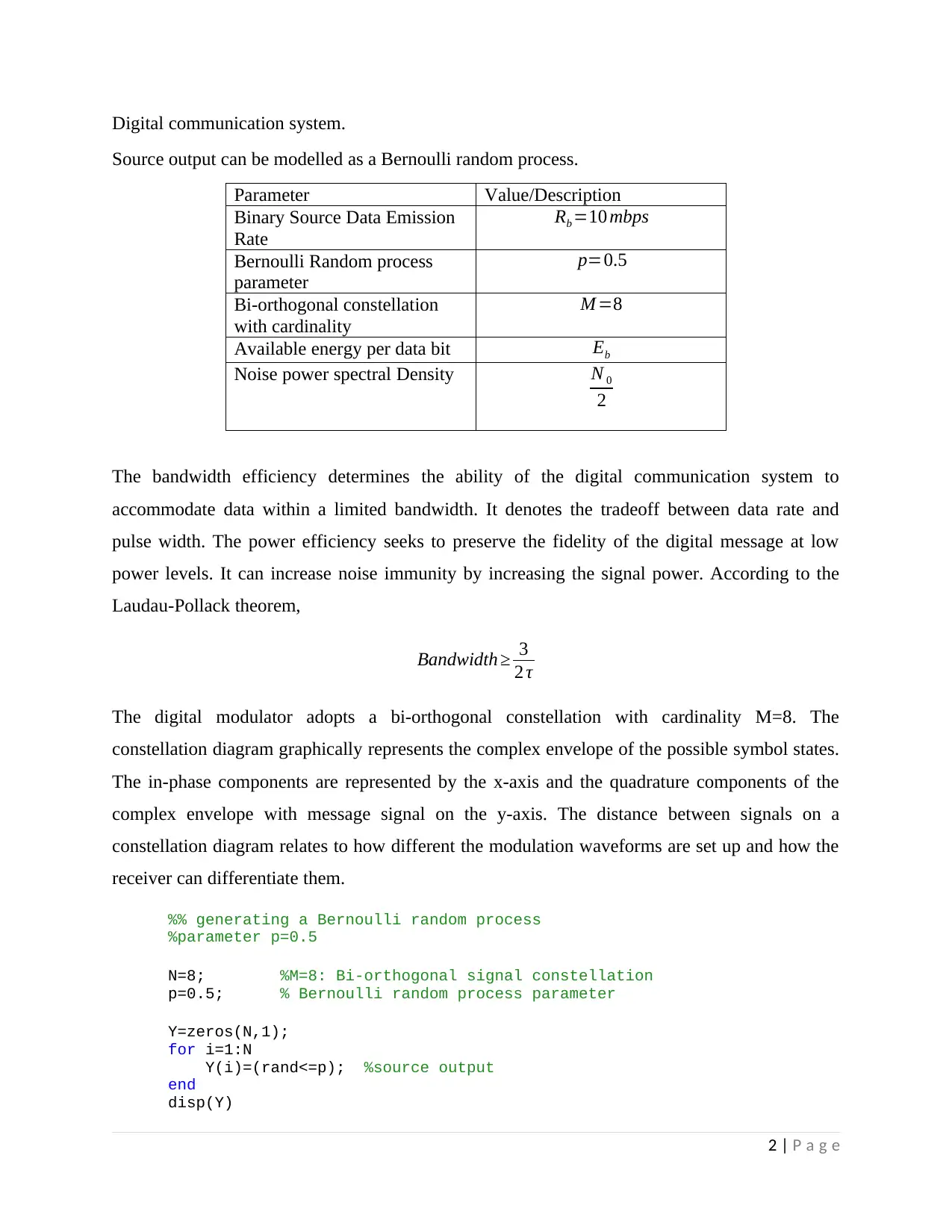
Source output can be modelled as a Bernoulli random process.
Parameter Value/Description
Binary Source Data Emission
Rate
Rb =10 mbps
Bernoulli Random process
parameter
p=0.5
Bi-orthogonal constellation
with cardinality
M =8
Available energy per data bit Eb
Noise power spectral Density N 0
2
The bandwidth efficiency determines the ability of the digital communication system to
accommodate data within a limited bandwidth. It denotes the tradeoff between data rate and
pulse width. The power efficiency seeks to preserve the fidelity of the digital message at low
power levels. It can increase noise immunity by increasing the signal power. According to the
Laudau-Pollack theorem,
Bandwidth ≥ 3
2 τ
The digital modulator adopts a bi-orthogonal constellation with cardinality M=8. The
constellation diagram graphically represents the complex envelope of the possible symbol states.
The in-phase components are represented by the x-axis and the quadrature components of the
complex envelope with message signal on the y-axis. The distance between signals on a
constellation diagram relates to how different the modulation waveforms are set up and how the
receiver can differentiate them.
%% generating a Bernoulli random process
%parameter p=0.5
N=8; %M=8: Bi-orthogonal signal constellation
p=0.5; % Bernoulli random process parameter
Y=zeros(N,1);
for i=1:N
Y(i)=(rand<=p); %source output
end
disp(Y)
2 | P a g e
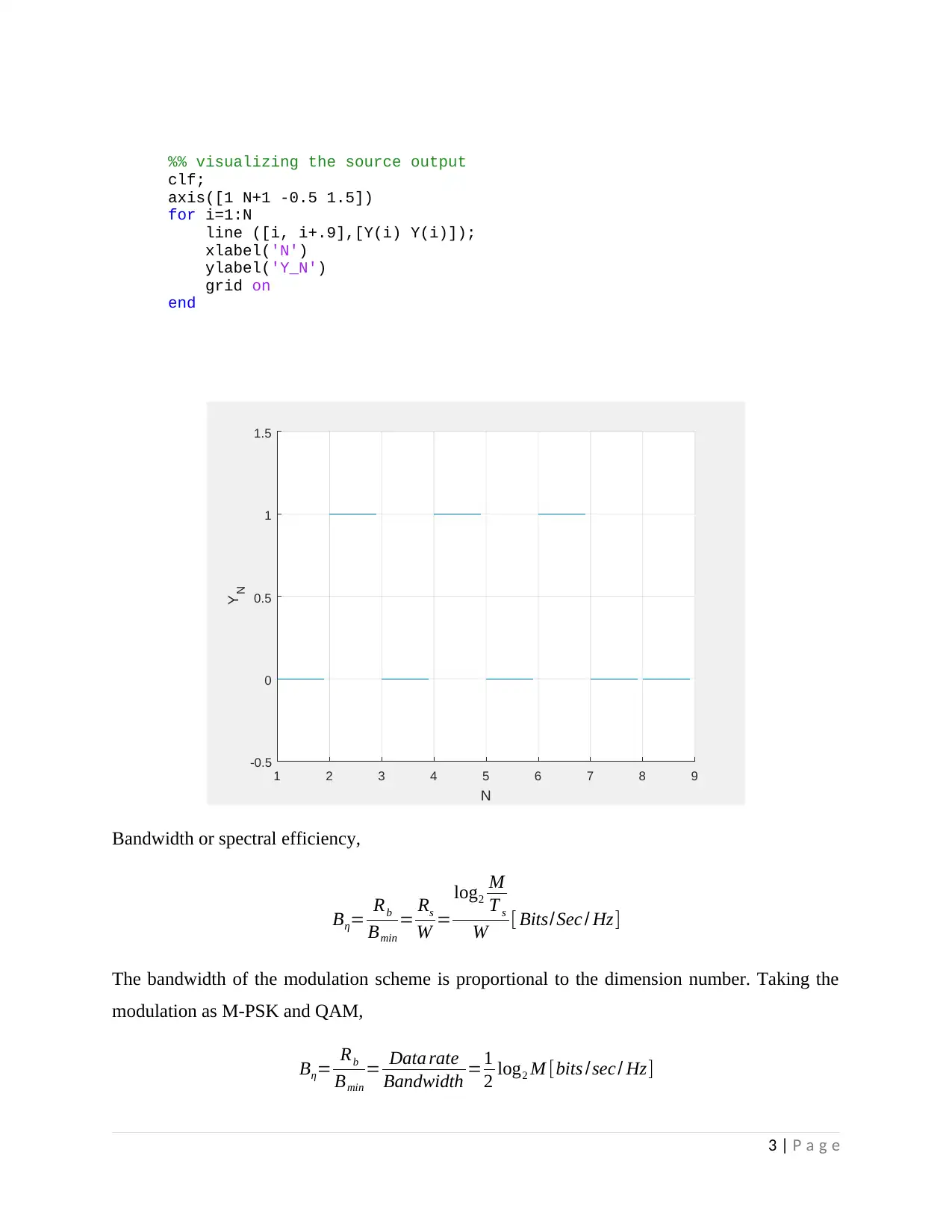
%% visualizing the source output
clf;
axis([1 N+1 -0.5 1.5])
for i=1:N
line ([i, i+.9],[Y(i) Y(i)]);
xlabel('N')
ylabel('Y_N')
grid on
end
1 2 3 4 5 6 7 8 9
N
-0.5
0
0.5
1
1.5
Y N
Bandwidth or spectral efficiency,
Bη= Rb
Bmin
= Rs
W =
log2
M
T s
W [ Bits/Sec / Hz]
The bandwidth of the modulation scheme is proportional to the dimension number. Taking the
modulation as M-PSK and QAM,
Bη= Rb
Bmin
= Data rate
Bandwidth =1
2 log2 M [bits /sec/ Hz]
3 | P a g e
⊘ This is a preview!⊘
Do you want full access?
Subscribe today to unlock all pages.

Trusted by 1+ million students worldwide
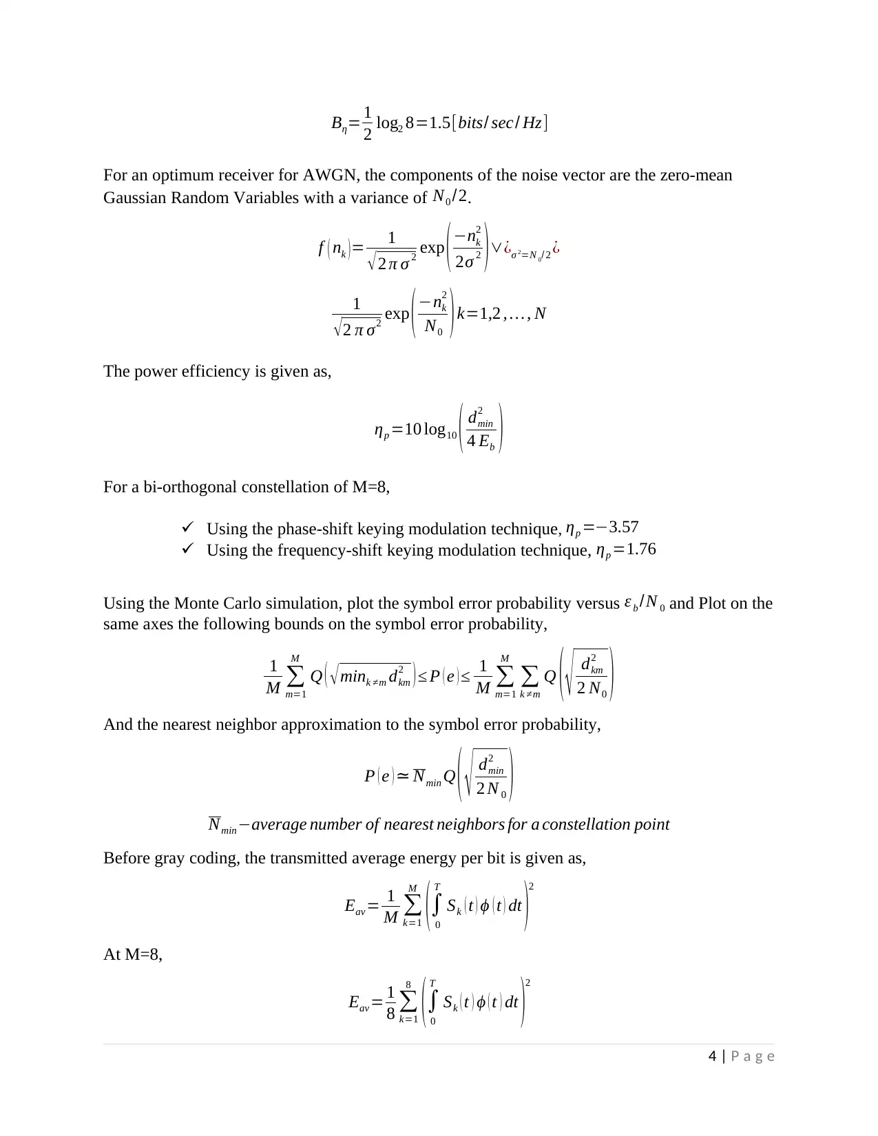
Bη= 1
2 log2 8=1.5[bits/ sec / Hz]
For an optimum receiver for AWGN, the components of the noise vector are the zero-mean
Gaussian Random Variables with a variance of N0 /2.
f ( nk ) = 1
√ 2 π σ 2 exp ( −nk
2
2σ 2 ) ∨¿σ 2=N 0/ 2 ¿
1
√2 π σ2 exp (−nk
2
N0 )k=1,2 , … , N
The power efficiency is given as,
ηp =10 log10 ( dmin
2
4 Eb )
For a bi-orthogonal constellation of M=8,
Using the phase-shift keying modulation technique, ηp =−3.57
Using the frequency-shift keying modulation technique, ηp =1.76
Using the Monte Carlo simulation, plot the symbol error probability versus ε b /N 0 and Plot on the
same axes the following bounds on the symbol error probability,
1
M ∑
m=1
M
Q ( √mink ≠m dkm
2 ) ≤ P ( e ) ≤ 1
M ∑
m=1
M
∑
k ≠m
Q ( √ dkm
2
2 N0 )
And the nearest neighbor approximation to the symbol error probability,
P ( e ) ≃ Nmin Q ( √ dmin
2
2 N 0 )
Nmin−average number of nearest neighbors for a constellation point
Before gray coding, the transmitted average energy per bit is given as,
Eav= 1
M ∑
k=1
M
(∫
0
T
Sk ( t ) ϕ ( t ) dt )2
At M=8,
Eav = 1
8 ∑
k=1
8
(∫
0
T
Sk ( t ) ϕ ( t ) dt )2
4 | P a g e
Paraphrase This Document
Need a fresh take? Get an instant paraphrase of this document with our AI Paraphraser
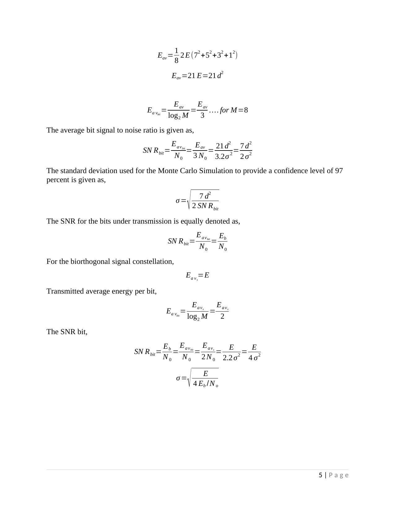
Eav = 1
8 2 E (72 +52 +32 +12)
Eav=21 E=21 d2
Ea vbit
= Eav
log2 M = Eav
3 … . for M =8
The average bit signal to noise ratio is given as,
SN Rbit= Ea vbit
N0
= Eav
3 N0
= 21 d2
3.2σ 2 = 7 d2
2 σ2
The standard deviation used for the Monte Carlo Simulation to provide a confidence level of 97
percent is given as,
σ = √ 7 d2
2 SN Rbit
The SNR for the bits under transmission is equally denoted as,
SN Rbit= Ea vbit
N0
= Eb
N0
For the biorthogonal signal constellation,
Ea vs
=E
Transmitted average energy per bit,
Ea vbit
= Ea vs
log2 M = Ea vs
2
The SNR bit,
SN Rbit= Eb
N 0
= Ea vbit
N 0
= Ea vs
2 N 0
= E
2.2 σ2 = E
4 σ2
σ = √ E
4 Eb /N o
5 | P a g e
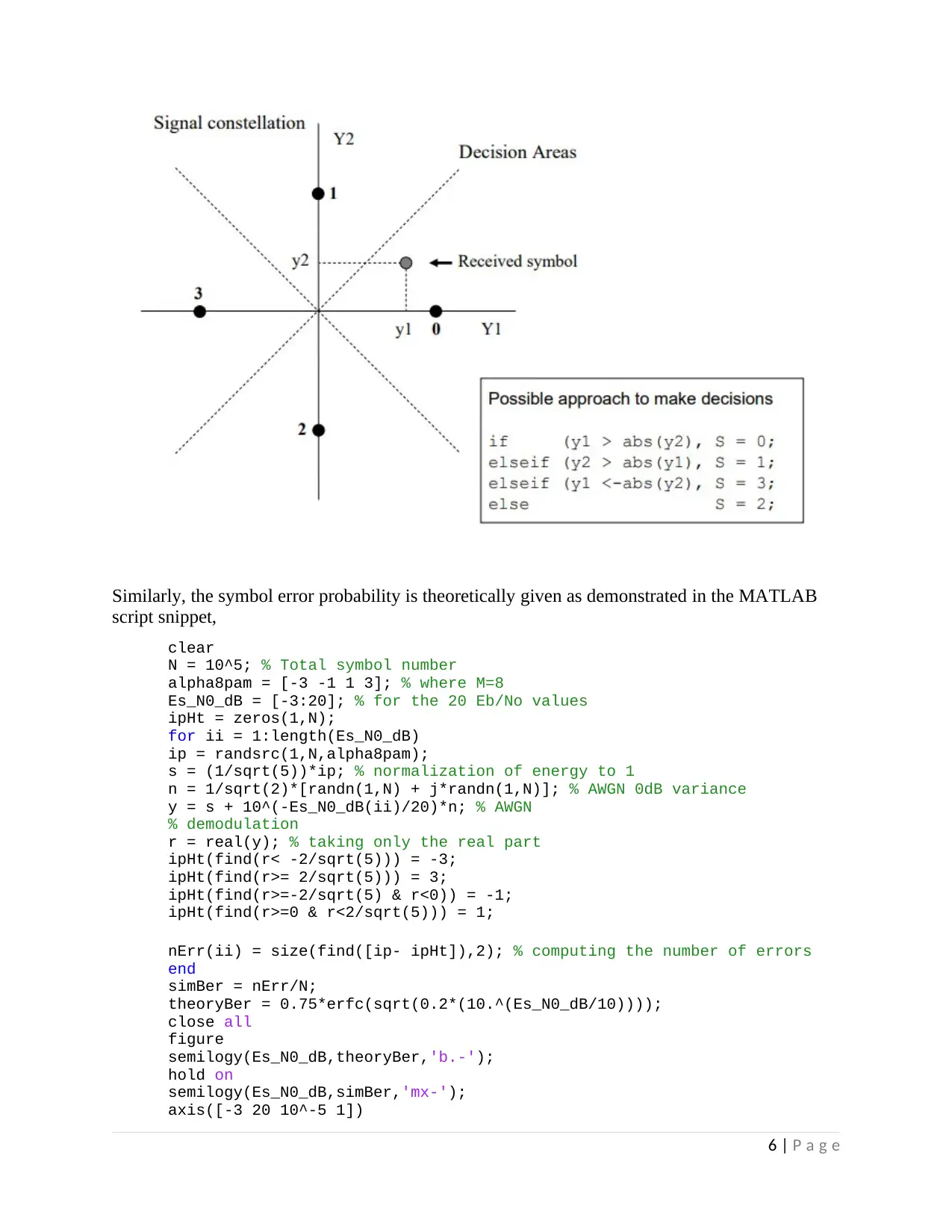
Similarly, the symbol error probability is theoretically given as demonstrated in the MATLAB
script snippet,
clear
N = 10^5; % Total symbol number
alpha8pam = [-3 -1 1 3]; % where M=8
Es_N0_dB = [-3:20]; % for the 20 Eb/No values
ipHt = zeros(1,N);
for ii = 1:length(Es_N0_dB)
ip = randsrc(1,N,alpha8pam);
s = (1/sqrt(5))*ip; % normalization of energy to 1
n = 1/sqrt(2)*[randn(1,N) + j*randn(1,N)]; % AWGN 0dB variance
y = s + 10^(-Es_N0_dB(ii)/20)*n; % AWGN
% demodulation
r = real(y); % taking only the real part
ipHt(find(r< -2/sqrt(5))) = -3;
ipHt(find(r>= 2/sqrt(5))) = 3;
ipHt(find(r>=-2/sqrt(5) & r<0)) = -1;
ipHt(find(r>=0 & r<2/sqrt(5))) = 1;
nErr(ii) = size(find([ip- ipHt]),2); % computing the number of errors
end
simBer = nErr/N;
theoryBer = 0.75*erfc(sqrt(0.2*(10.^(Es_N0_dB/10))));
close all
figure
semilogy(Es_N0_dB,theoryBer,'b.-');
hold on
semilogy(Es_N0_dB,simBer,'mx-');
axis([-3 20 10^-5 1])
6 | P a g e
⊘ This is a preview!⊘
Do you want full access?
Subscribe today to unlock all pages.

Trusted by 1+ million students worldwide
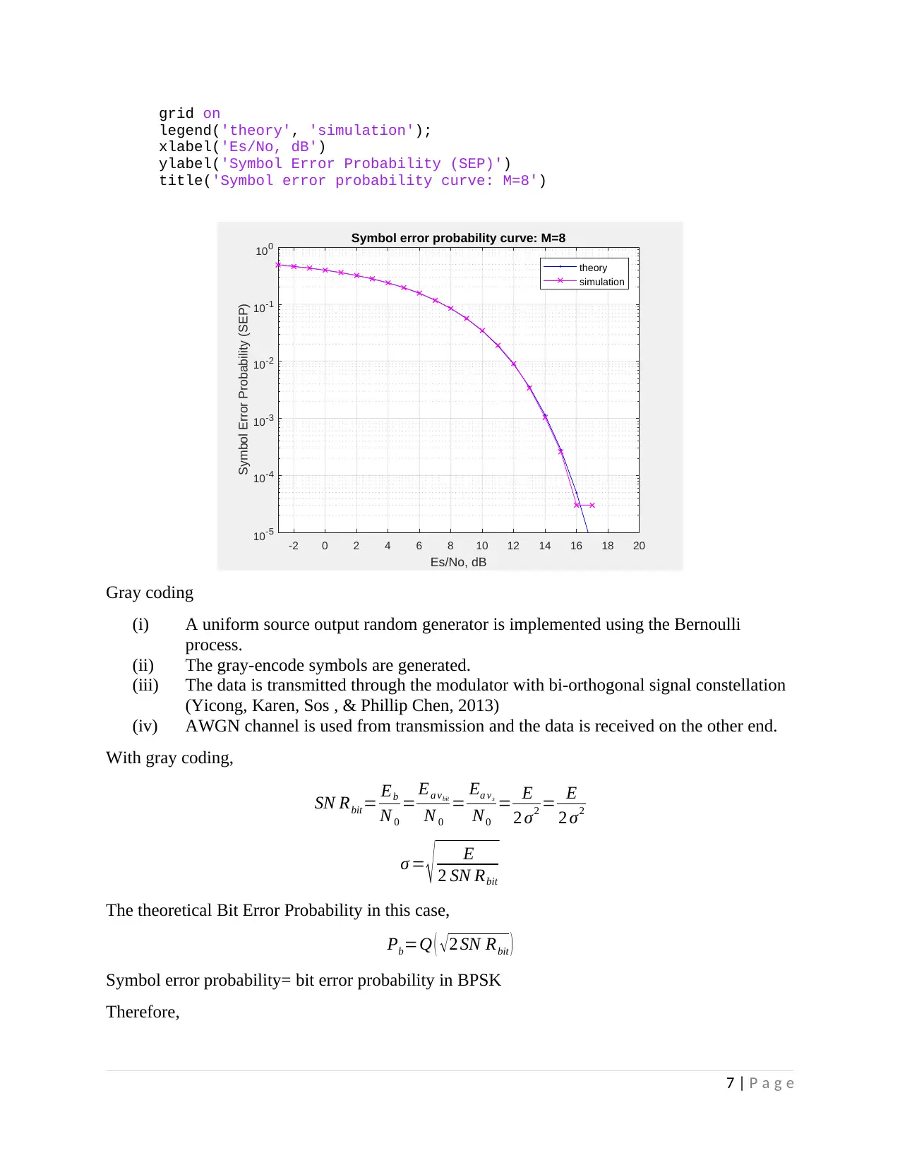
grid on
legend('theory', 'simulation');
xlabel('Es/No, dB')
ylabel('Symbol Error Probability (SEP)')
title('Symbol error probability curve: M=8')
-2 0 2 4 6 8 10 12 14 16 18 20
Es/No, dB
10 -5
10 -4
10 -3
10 -2
10 -1
10 0
Symbol Error Probability (SEP)
Symbol error probability curve: M=8
theory
simulation
Gray coding
(i) A uniform source output random generator is implemented using the Bernoulli
process.
(ii) The gray-encode symbols are generated.
(iii) The data is transmitted through the modulator with bi-orthogonal signal constellation
(Yicong, Karen, Sos , & Phillip Chen, 2013)
(iv) AWGN channel is used from transmission and the data is received on the other end.
With gray coding,
SN Rbit= Eb
N 0
= Ea vbit
N 0
= Ea vs
N0
= E
2 σ2 = E
2 σ2
σ = √ E
2 SN Rbit
The theoretical Bit Error Probability in this case,
Pb=Q ( √2 SN Rbit )
Symbol error probability= bit error probability in BPSK
Therefore,
7 | P a g e
Paraphrase This Document
Need a fresh take? Get an instant paraphrase of this document with our AI Paraphraser
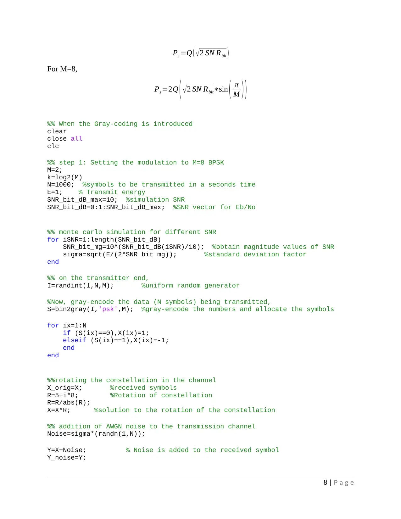
Ps =Q ( √2 SN Rbit )
For M=8,
Ps =2Q ( √ 2 SN Rbit∗sin ( π
M ) )
%% When the Gray-coding is introduced
clear
close all
clc
%% step 1: Setting the modulation to M=8 BPSK
M=2;
k=log2(M)
N=1000; %symbols to be transmitted in a seconds time
E=1; % Transmit energy
SNR_bit_dB_max=10; %simulation SNR
SNR_bit_dB=0:1:SNR_bit_dB_max; %SNR vector for Eb/No
%% monte carlo simulation for different SNR
for iSNR=1:length(SNR_bit_dB)
SNR_bit_mg=10^(SNR_bit_dB(iSNR)/10); %obtain magnitude values of SNR
sigma=sqrt(E/(2*SNR_bit_mg)); %standard deviation factor
end
%% on the transmitter end,
I=randint(1,N,M); %uniform random generator
%Now, gray-encode the data (N symbols) being transmitted,
S=bin2gray(I,'psk',M); %gray-encode the numbers and allocate the symbols
for ix=1:N
if (S(ix)==0),X(ix)=1;
elseif (S(ix)==1),X(ix)=-1;
end
end
%%rotating the constellation in the channel
X_orig=X; %received symbols
R=5+i*8; %Rotation of constellation
R=R/abs(R);
X=X*R; %solution to the rotation of the constellation
%% addition of AWGN noise to the transmission channel
Noise=sigma*(randn(1,N));
Y=X+Noise; % Noise is added to the received symbol
Y_noise=Y;
8 | P a g e
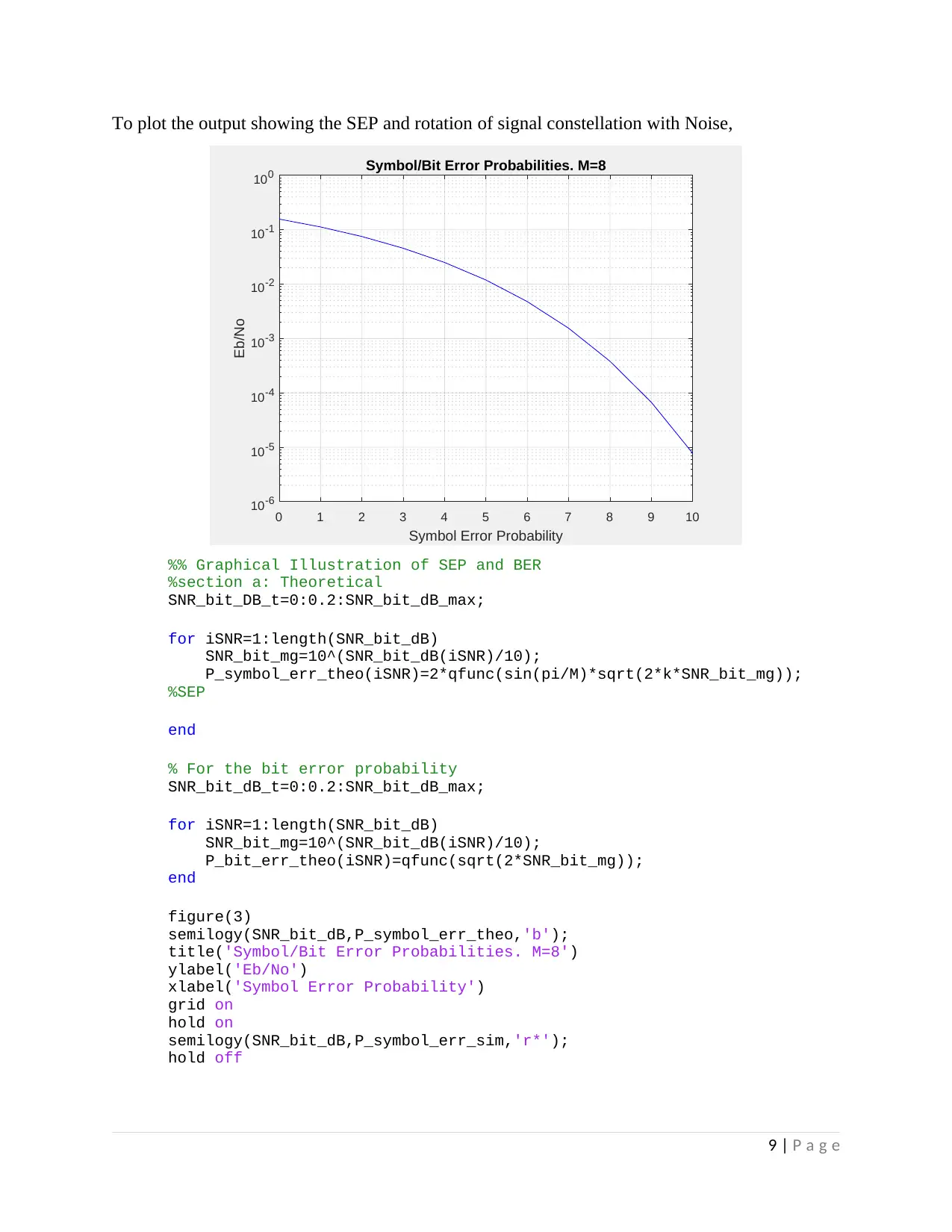
To plot the output showing the SEP and rotation of signal constellation with Noise,
0 1 2 3 4 5 6 7 8 9 10
Symbol Error Probability
10-6
10-5
10-4
10-3
10-2
10-1
100
Eb/No
Symbol/Bit Error Probabilities. M=8
%% Graphical Illustration of SEP and BER
%section a: Theoretical
SNR_bit_DB_t=0:0.2:SNR_bit_dB_max;
for iSNR=1:length(SNR_bit_dB)
SNR_bit_mg=10^(SNR_bit_dB(iSNR)/10);
P_symbol_err_theo(iSNR)=2*qfunc(sin(pi/M)*sqrt(2*k*SNR_bit_mg));
%SEP
end
% For the bit error probability
SNR_bit_dB_t=0:0.2:SNR_bit_dB_max;
for iSNR=1:length(SNR_bit_dB)
SNR_bit_mg=10^(SNR_bit_dB(iSNR)/10);
P_bit_err_theo(iSNR)=qfunc(sqrt(2*SNR_bit_mg));
end
figure(3)
semilogy(SNR_bit_dB,P_symbol_err_theo,'b');
title('Symbol/Bit Error Probabilities. M=8')
ylabel('Eb/No')
xlabel('Symbol Error Probability')
grid on
hold on
semilogy(SNR_bit_dB,P_symbol_err_sim,'r*');
hold off
9 | P a g e
⊘ This is a preview!⊘
Do you want full access?
Subscribe today to unlock all pages.

Trusted by 1+ million students worldwide
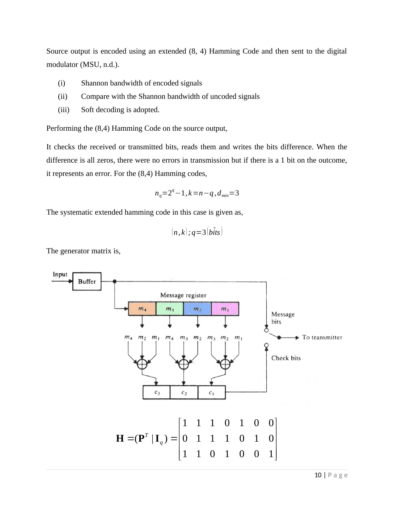
Source output is encoded using an extended (8, 4) Hamming Code and then sent to the digital
modulator (MSU, n.d.).
(i) Shannon bandwidth of encoded signals
(ii) Compare with the Shannon bandwidth of uncoded signals
(iii) Soft decoding is adopted.
Performing the (8,4) Hamming Code on the source output,
It checks the received or transmitted bits, reads them and writes the bits difference. When the
difference is all zeros, there were no errors in transmission but if there is a 1 bit on the outcome,
it represents an error. For the (8,4) Hamming codes,
nq=2q −1, k =n−q , dmin=3
The systematic extended hamming code in this case is given as,
( n , k ) ; q=3 ( ˇbits )
The generator matrix is,
1 1 1 0 1 0 0
( | ) 0 1 1 1 0 1 0
1 1 0 1 0 0 1
T
q
H P I
10 | P a g e
Paraphrase This Document
Need a fresh take? Get an instant paraphrase of this document with our AI Paraphraser
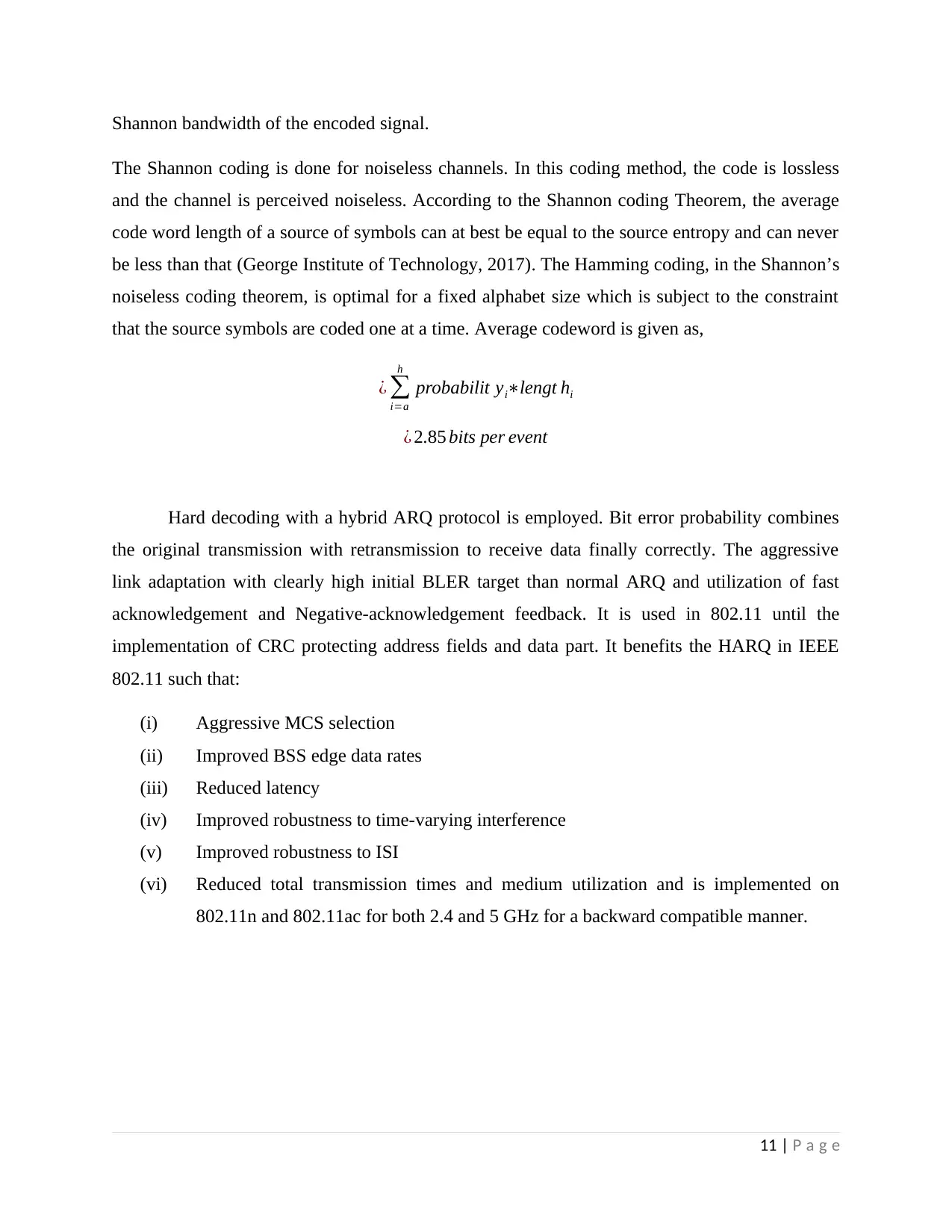
Shannon bandwidth of the encoded signal.
The Shannon coding is done for noiseless channels. In this coding method, the code is lossless
and the channel is perceived noiseless. According to the Shannon coding Theorem, the average
code word length of a source of symbols can at best be equal to the source entropy and can never
be less than that (George Institute of Technology, 2017). The Hamming coding, in the Shannon’s
noiseless coding theorem, is optimal for a fixed alphabet size which is subject to the constraint
that the source symbols are coded one at a time. Average codeword is given as,
¿ ∑
i=a
h
probabilit yi∗lengt hi
¿ 2.85 bits per event
Hard decoding with a hybrid ARQ protocol is employed. Bit error probability combines
the original transmission with retransmission to receive data finally correctly. The aggressive
link adaptation with clearly high initial BLER target than normal ARQ and utilization of fast
acknowledgement and Negative-acknowledgement feedback. It is used in 802.11 until the
implementation of CRC protecting address fields and data part. It benefits the HARQ in IEEE
802.11 such that:
(i) Aggressive MCS selection
(ii) Improved BSS edge data rates
(iii) Reduced latency
(iv) Improved robustness to time-varying interference
(v) Improved robustness to ISI
(vi) Reduced total transmission times and medium utilization and is implemented on
802.11n and 802.11ac for both 2.4 and 5 GHz for a backward compatible manner.
11 | P a g e
REFERENCES
George Institute of Technology. (2017). Coding Theory and Application. Retrieved from Georgia
Tech Lorraine: Modification of a Hamming Code:
http://bloch.ece.gatech.edu/sp10_ece6606/code_modifications.pdf
MSU. (n.d.). Hamming Codes. Retrieved from First-order Reed-Muller Codes:
http://users.math.msu.edu/users/jhall/classes/codenotes/Hamming.pdf
Yicong, Z., Karen, P., Sos , A., & Phillip Chen, C. L. (2013). (n, k, p)-Gray Code for Image
Systems. IEEE Transactions on Cybernetics, 515-529.
12 | P a g e
⊘ This is a preview!⊘
Do you want full access?
Subscribe today to unlock all pages.

Trusted by 1+ million students worldwide
1 out of 12
Your All-in-One AI-Powered Toolkit for Academic Success.
+13062052269
info@desklib.com
Available 24*7 on WhatsApp / Email
![[object Object]](/_next/static/media/star-bottom.7253800d.svg)
Unlock your academic potential
Copyright © 2020–2026 A2Z Services. All Rights Reserved. Developed and managed by ZUCOL.
