Digital Logic and Circuit Design Homework 2 Solutions - ECE 201
VerifiedAdded on 2023/04/21
|8
|1121
|457
Homework Assignment
AI Summary
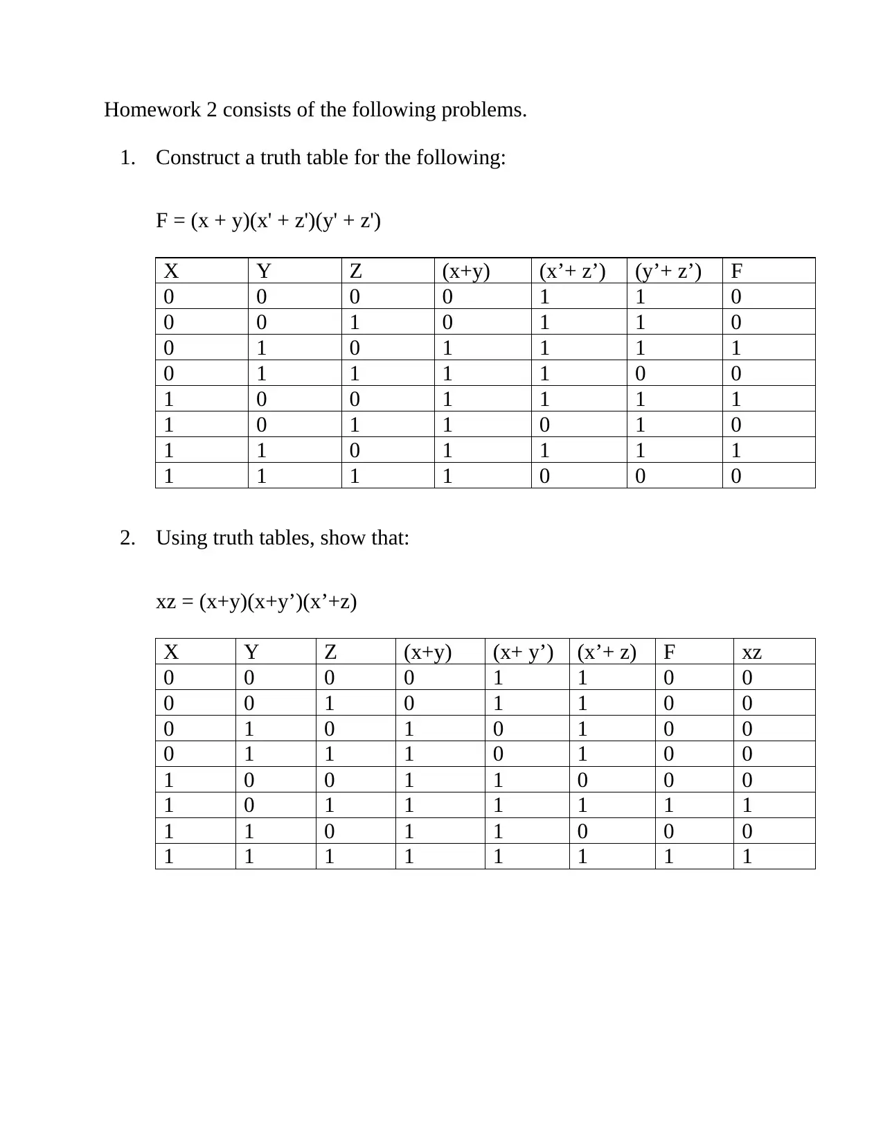
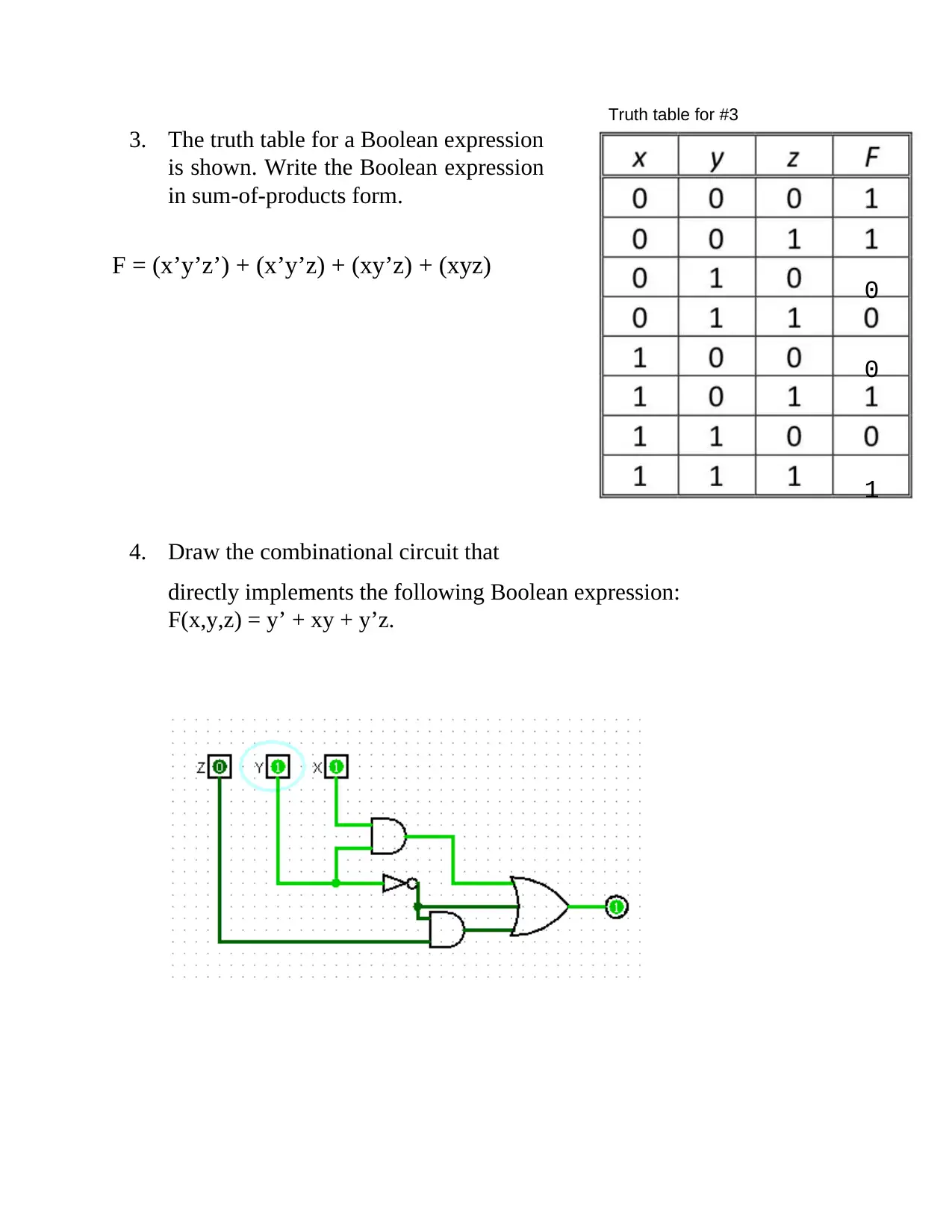
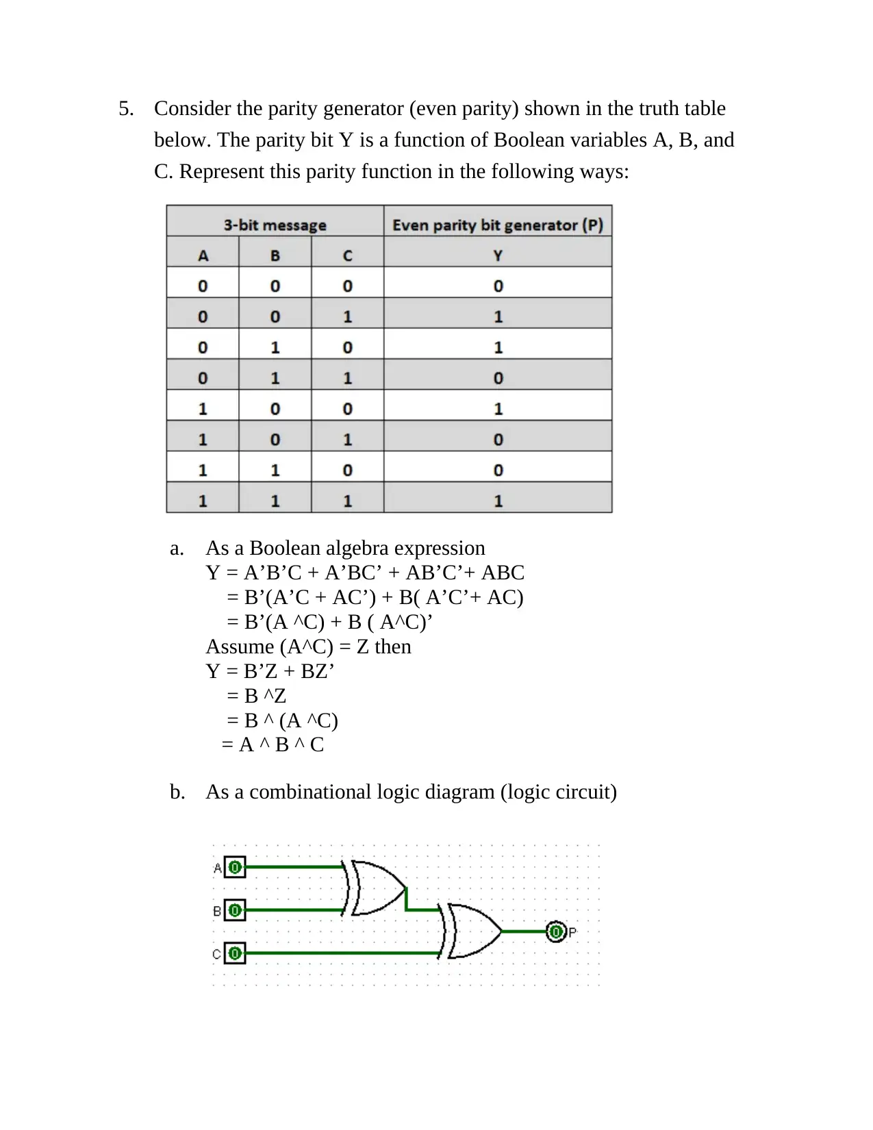
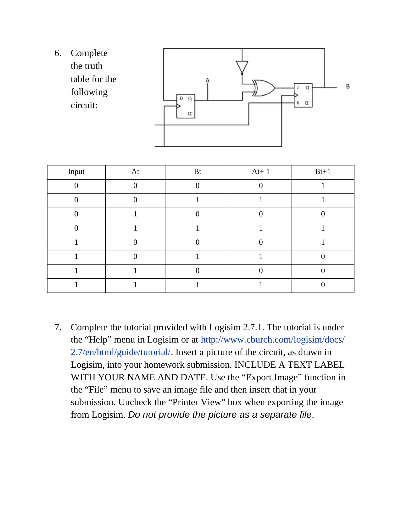
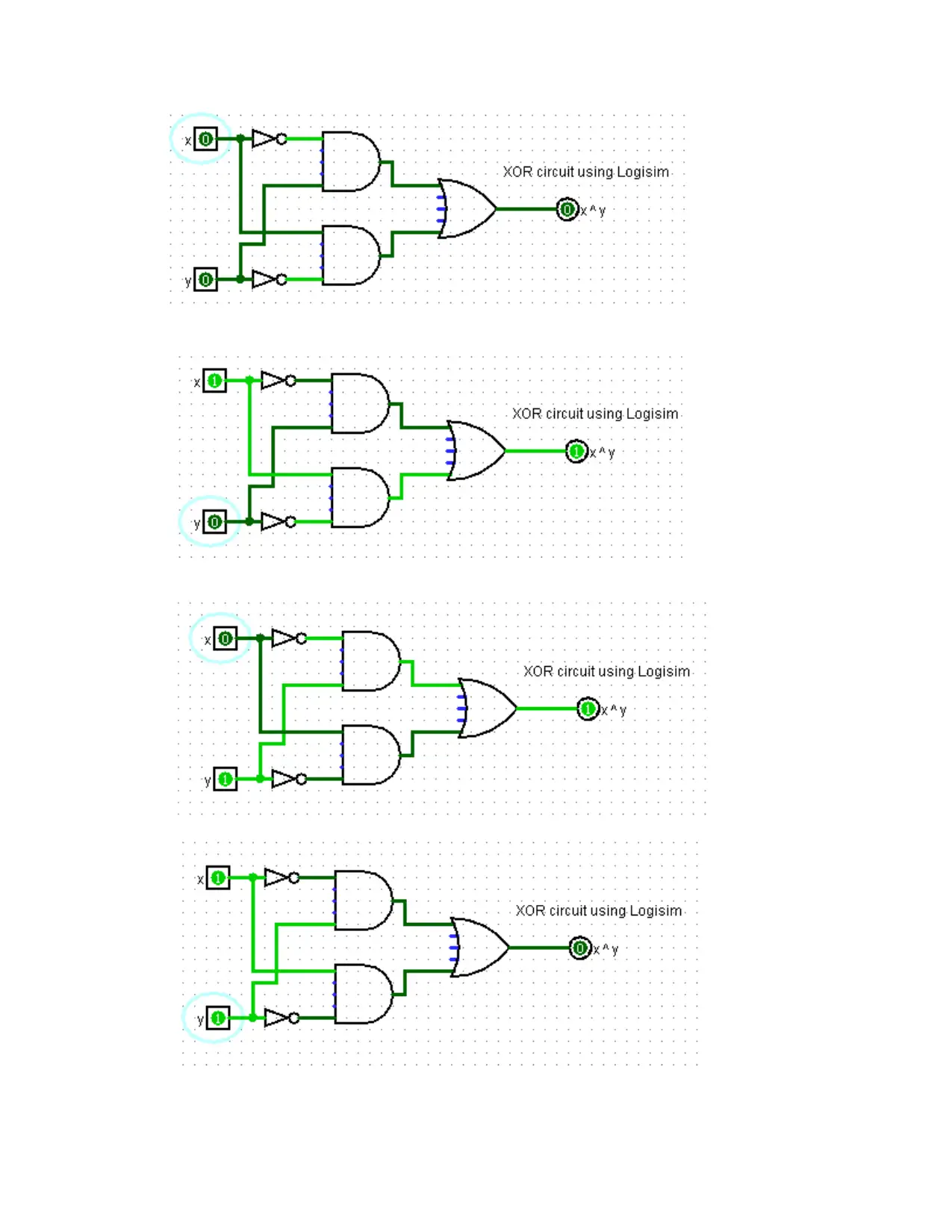
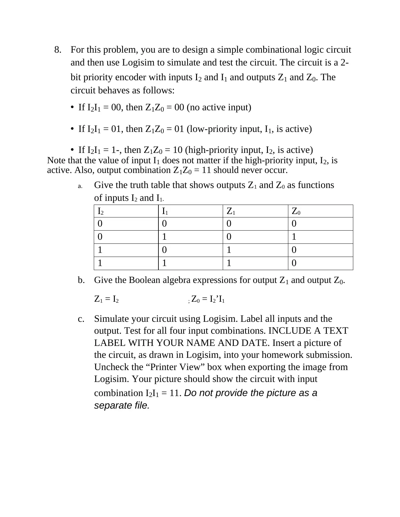
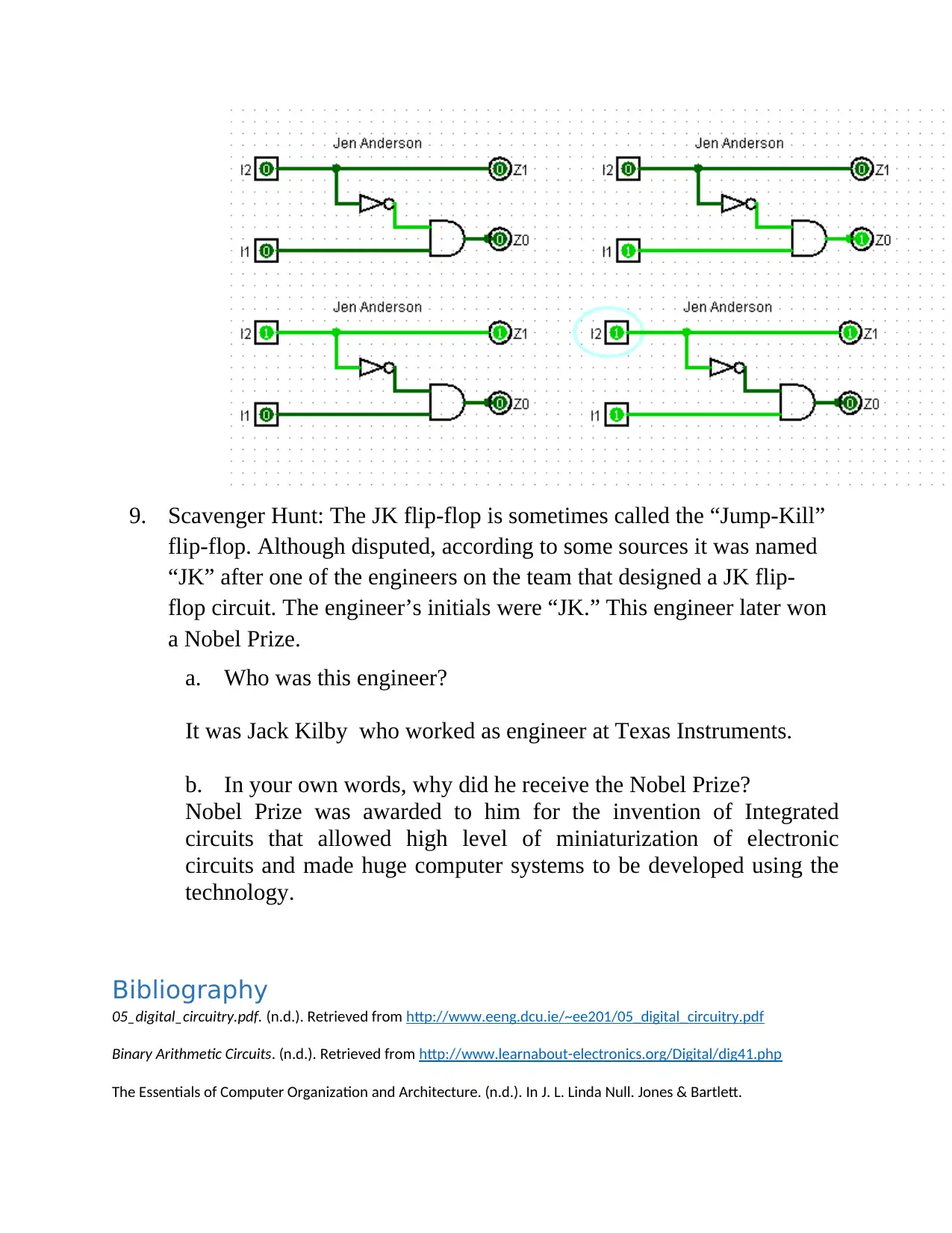
This homework assignment focuses on fundamental concepts in digital logic and circuit design. The assignment includes constructing truth tables for Boolean expressions, using truth tables to prove Boolean identities, writing Boolean expressions in sum-of-products form, and drawing combinational circuits. Students are required to analyze and design circuits, including a parity generator and a 2-bit priority encoder. The use of the Logisim simulator is central to the assignment, requiring students to create and test circuits within the software. Additionally, the assignment includes questions on memory addressing, RAM chip configurations, and instruction set design, as well as a scavenger hunt question related to the JK flip-flop. The solutions provided cover all aspects of the assigned problems, including detailed steps and circuit diagrams.

• Download the Logisim 2.7.1 from http://sourceforge.net/projects/circuit/. Logisim is a simple
logic simulator designed for educational use. Pick the platform appropriate for your
computer. You will need Logisim for this homework and later assignments. More information
about Logisim is available at http://www.cburch.com/logisim/.
logic simulator designed for educational use. Pick the platform appropriate for your
computer. You will need Logisim for this homework and later assignments. More information
about Logisim is available at http://www.cburch.com/logisim/.
Paraphrase This Document
Need a fresh take? Get an instant paraphrase of this document with our AI Paraphraser

Homework 2 consists of the following problems.
1. Construct a truth table for the following:
F = (x + y)(x' + z')(y' + z')
X Y Z (x+y) (x’+ z’) (y’+ z’) F
0 0 0 0 1 1 0
0 0 1 0 1 1 0
0 1 0 1 1 1 1
0 1 1 1 1 0 0
1 0 0 1 1 1 1
1 0 1 1 0 1 0
1 1 0 1 1 1 1
1 1 1 1 0 0 0
2. Using truth tables, show that:
xz = (x+y)(x+y’)(x’+z)
X Y Z (x+y) (x+ y’) (x’+ z) F xz
0 0 0 0 1 1 0 0
0 0 1 0 1 1 0 0
0 1 0 1 0 1 0 0
0 1 1 1 0 1 0 0
1 0 0 1 1 0 0 0
1 0 1 1 1 1 1 1
1 1 0 1 1 0 0 0
1 1 1 1 1 1 1 1

Truth table for #3
3. The truth table for a Boolean expression
is shown. Write the Boolean expression
in sum-of-products form.
F = (x’y’z’) + (x’y’z) + (xy’z) + (xyz) 0
0
1
4. Draw the combinational circuit that
directly implements the following Boolean expression:
F(x,y,z) = y’ + xy + y’z.
3. The truth table for a Boolean expression
is shown. Write the Boolean expression
in sum-of-products form.
F = (x’y’z’) + (x’y’z) + (xy’z) + (xyz) 0
0
1
4. Draw the combinational circuit that
directly implements the following Boolean expression:
F(x,y,z) = y’ + xy + y’z.
⊘ This is a preview!⊘
Do you want full access?
Subscribe today to unlock all pages.

Trusted by 1+ million students worldwide

5. Consider the parity generator (even parity) shown in the truth table
below. The parity bit Y is a function of Boolean variables A, B, and
C. Represent this parity function in the following ways:
a. As a Boolean algebra expression
Y = A’B’C + A’BC’ + AB’C’+ ABC
= B’(A’C + AC’) + B( A’C’+ AC)
= B’(A ^C) + B ( A^C)’
Assume (A^C) = Z then
Y = B’Z + BZ’
= B ^Z
= B ^ (A ^C)
= A ^ B ^ C
b. As a combinational logic diagram (logic circuit)
Paraphrase This Document
Need a fresh take? Get an instant paraphrase of this document with our AI Paraphraser

6. Complete
the truth
table for the
following
circuit:
Input At Bt At+ 1 Bt+1
0 0 0 0 1
0 0 1 1 1
0 1 0 0 0
0 1 1 1 1
1 0 0 0 1
1 0 1 1 0
1 1 0 0 0
1 1 1 1 0
7. Complete the tutorial provided with Logisim 2.7.1. The tutorial is under
the “Help” menu in Logisim or at http://www.cburch.com/logisim/docs/
2.7/en/html/guide/tutorial/. Insert a picture of the circuit, as drawn in
Logisim, into your homework submission. INCLUDE A TEXT LABEL
WITH YOUR NAME AND DATE. Use the “Export Image” function in
the “File” menu to save an image file and then insert that in your
submission. Uncheck the “Printer View” box when exporting the image
from Logisim. Do not provide the picture as a separate file.

⊘ This is a preview!⊘
Do you want full access?
Subscribe today to unlock all pages.

Trusted by 1+ million students worldwide

8. For this problem, you are to design a simple combinational logic circuit
and then use Logisim to simulate and test the circuit. The circuit is a 2-
bit priority encoder with inputs I2 and I1 and outputs Z1 and Z0. The
circuit behaves as follows:
• If I2I1 = 00, then Z1Z0 = 00 (no active input)
• If I2I1 = 01, then Z1Z0 = 01 (low-priority input, I1, is active)
• If I2I1 = 1-, then Z1Z0 = 10 (high-priority input, I2, is active)
Note that the value of input I1 does not matter if the high-priority input, I2, is
active. Also, output combination Z1Z0 = 11 should never occur.
a. Give the truth table that shows outputs Z1 and Z0 as functions
of inputs I2 and I1.
I2 I1 Z1 Z0
0 0 0 0
0 1 0 1
1 0 1 0
1 1 1 0
b. Give the Boolean algebra expressions for output Z1 and output Z0.
Z1 = I2 ; Z0 = I2’I1
c. Simulate your circuit using Logisim. Label all inputs and the
output. Test for all four input combinations. INCLUDE A TEXT
LABEL WITH YOUR NAME AND DATE. Insert a picture of
the circuit, as drawn in Logisim, into your homework submission.
Uncheck the “Printer View” box when exporting the image from
Logisim. Your picture should show the circuit with input
combination I2I1 = 11. Do not provide the picture as a
separate file.
Paraphrase This Document
Need a fresh take? Get an instant paraphrase of this document with our AI Paraphraser

9. Scavenger Hunt: The JK flip-flop is sometimes called the “Jump-Kill”
flip-flop. Although disputed, according to some sources it was named
“JK” after one of the engineers on the team that designed a JK flip-
flop circuit. The engineer’s initials were “JK.” This engineer later won
a Nobel Prize.
a. Who was this engineer?
It was Jack Kilby who worked as engineer at Texas Instruments.
b. In your own words, why did he receive the Nobel Prize?
Nobel Prize was awarded to him for the invention of Integrated
circuits that allowed high level of miniaturization of electronic
circuits and made huge computer systems to be developed using the
technology.
Bibliography
05_digital_circuitry.pdf. (n.d.). Retrieved from http://www.eeng.dcu.ie/~ee201/05_digital_circuitry.pdf
Binary Arithmetic Circuits. (n.d.). Retrieved from http://www.learnabout-electronics.org/Digital/dig41.php
The Essentials of Computer Organization and Architecture. (n.d.). In J. L. Linda Null. Jones & Bartlett.
1 out of 8
Related Documents
Your All-in-One AI-Powered Toolkit for Academic Success.
+13062052269
info@desklib.com
Available 24*7 on WhatsApp / Email
Unlock your academic potential
Copyright © 2020–2025 A2Z Services. All Rights Reserved. Developed and managed by ZUCOL.


