ProductsLogo
LogoStudy Documents
LogoAI Grader
LogoAI Answer
LogoAI Code Checker
LogoPlagiarism Checker
LogoAI Paraphraser
LogoAI Quiz
LogoAI Detector
PricingBlogAbout Us
logo

Feedback Control Strategy for a Dye Injection Process

Verified

Added on  2023/06/07

|9
|1918
|455
AI Summary
This article discusses the design of a feedback control strategy for a dye injection process in industrial automation. It covers the use of a PID controller to control the mixer and improve the dye injection process. The article also discusses the use of a cascaded architecture to control the two process variables and achieve system stability. Safety and environmental considerations are also discussed.

Contribute Materials

Your contribution can guide someone’s learning journey. Share your documents today.
Document Page
MASTER OF ENGINEERING
(INDUSTRIAL AUTOMATION)-MIA
ME503 INDUSTRIAL PROCESS CONTROL SYSTEMS
ASSIGNMENT 2
V1.0
STUDENT NAME
STUDENT ID NUMBER
PROFESSOR (TUTOR)
DATE OF SUBMISSION

Secure Best Marks with AI Grader

Need help grading? Try our AI Grader for instant feedback on your assignments.
Document Page
ASSIGNMENT 2- PROJECT MIDTERM
FEEDBACK CONTROL STRATEGY FOR A DYE INJECTION PROCESS.
INTRODUCTION
Dye injection systems are used in both large and small scale applications. The system is
used to dye clothing based on set instructions. The amount of dye input in the pipe with flowing
water determines the concentration of a color on the cloth. The mixer mixes the dye and the
water together to ensure proper consistency of the two inputs before releasing the liquid into the
pipe. Such a system requires a controller to ensure that the desired level of concentration is
obtained at the output [1]. The system has inputs and output as described in the table below,
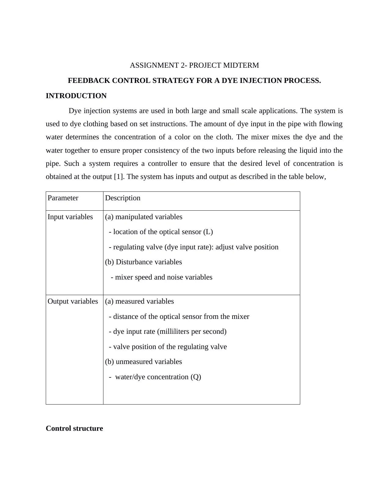
Parameter Description
Input variables (a) manipulated variables
- location of the optical sensor (L)
- regulating valve (dye input rate): adjust valve position
(b) Disturbance variables
- mixer speed and noise variables
Output variables (a) measured variables
- distance of the optical sensor from the mixer
- dye input rate (milliliters per second)
- valve position of the regulating valve
(b) unmeasured variables
- water/dye concentration (Q)
Control structure
Document Page
An open loop system can easily become unstable and it is important to use a feedback
loop which tests for errors. The feedback loop takes the input and compares it to the reference
input. The difference between the two process variables is the error of the system. Some of the
key causes of errors in such systems are disturbances from the external and internal environment
of the system. There are a number of control structure which can be implemented in such a
situation such as the proportional, proportional-integral, and the proportional-integral-derivative
controllers. These controllers can be implemented for system in the first order, second order, and
other higher orders. The proportional controller is used in the first order systems. It manipulates
a proportional gain constant which is used to alter the value of the output. The gain parameter is
multiplied with the system first order system to give a new yield to the system. The gain
parameter minimizes the steady state error but it does not eliminate the errors. The gain
parameter is denoted as, Kp. Adjusting the value increasingly minimizes the steady state error.
The value may be increased to a given value which is consider the optimum value which results
in a reduced amplitude and phase margin. Exceeding the value may cause the output to oscillate
during dead time or lag. The proportional-integral controller, on the other hand, eliminates the
steady state error completely. The control parameters are denoted as Kp and Ki. The controller is
implemented in areas where speed is not a performance factor. Unfortunately, the controller is
not able to predict future errors in the system and it is not able to reduce the rise time nor
eliminate the oscillations that may result when the value of the proportional gain parameter is
very high. The PID controller solves the issues that other controllers are unable to solve. It
guarantees optimum control dynamics to obtain zero steady state error, faster response which
implies a shorter rise time, no oscillations, no overshoots, and higher stability. The controller can
be implemented in systems of higher orders unlike the proportional controller which is limited to
first order systems only [2].
PROBLEM STATEMENT
The dye injection system has the dye injection and water as the inputs. The two meet at
the mixer and the mixer mixes the components to form a concentration which flows forward.
There is an optical sensor along the film which monitors the dye/water concentration. A black
dye is used to design the shirts which blends with the water and is mixed at the mixer. There is
need to have controllers that monitor the amount of dye that is allowed to flow through the
regulating valve. Another controller is needed to determine if the mixing process is correct and if
Document Page
it is done within the estimated time before it flows to the collection point or the output. The
optical sensor or detection may be placed at a distance too far from the mixer such that it may
fail to provide the correct dye/water concentration which could lead to destabilization of the
system or process.
AIMS & OBJECTIVES
a) To design a controller for the mixer to ensure that the desired dye/water concentration is
sent to the collection or output point.
b) To determine the type of controller to be implemented, the control valve model as well as
model a feedback control loop.
METHODOLOGY
Design of a PID controller that control the mixer and improves the dye injection process.
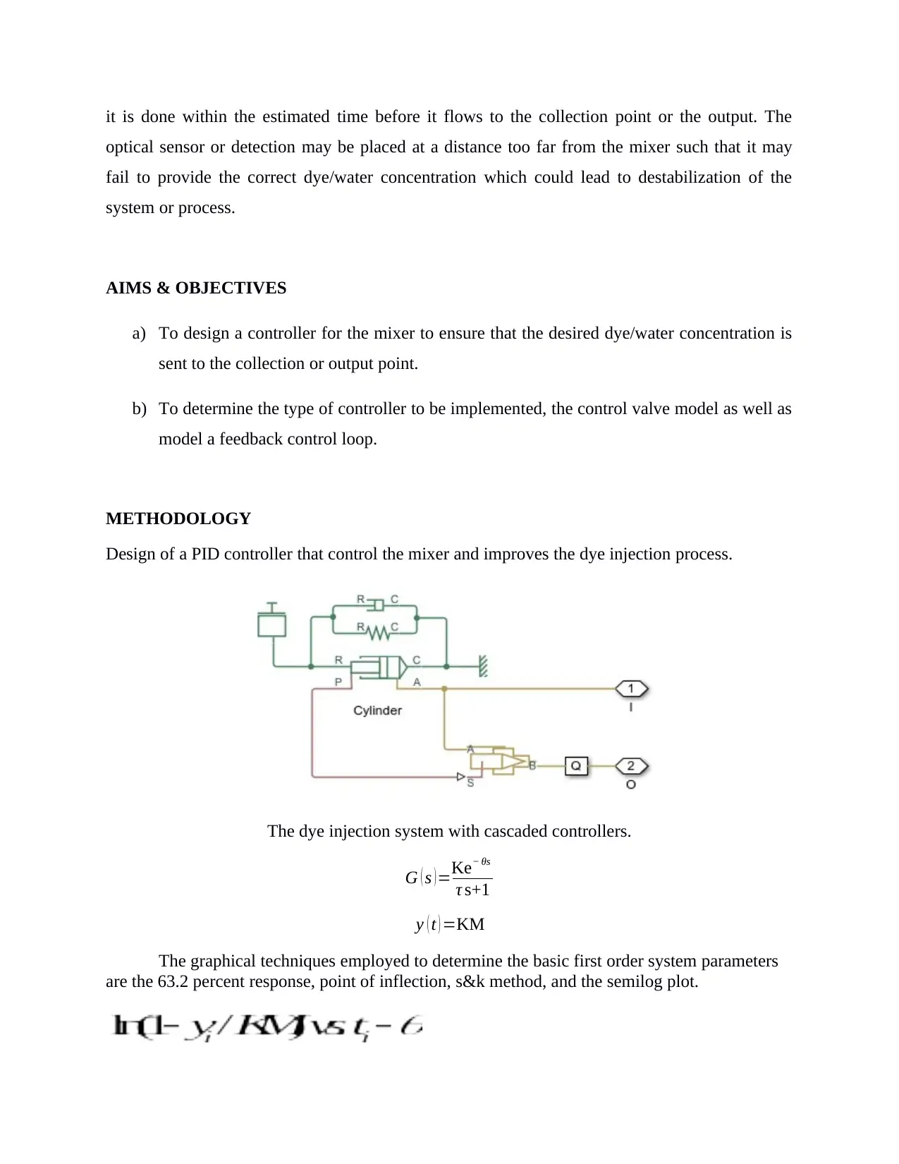
The dye injection system with cascaded controllers.
G ( s )=Ke θs
τ s+1
y ( t ) =KM
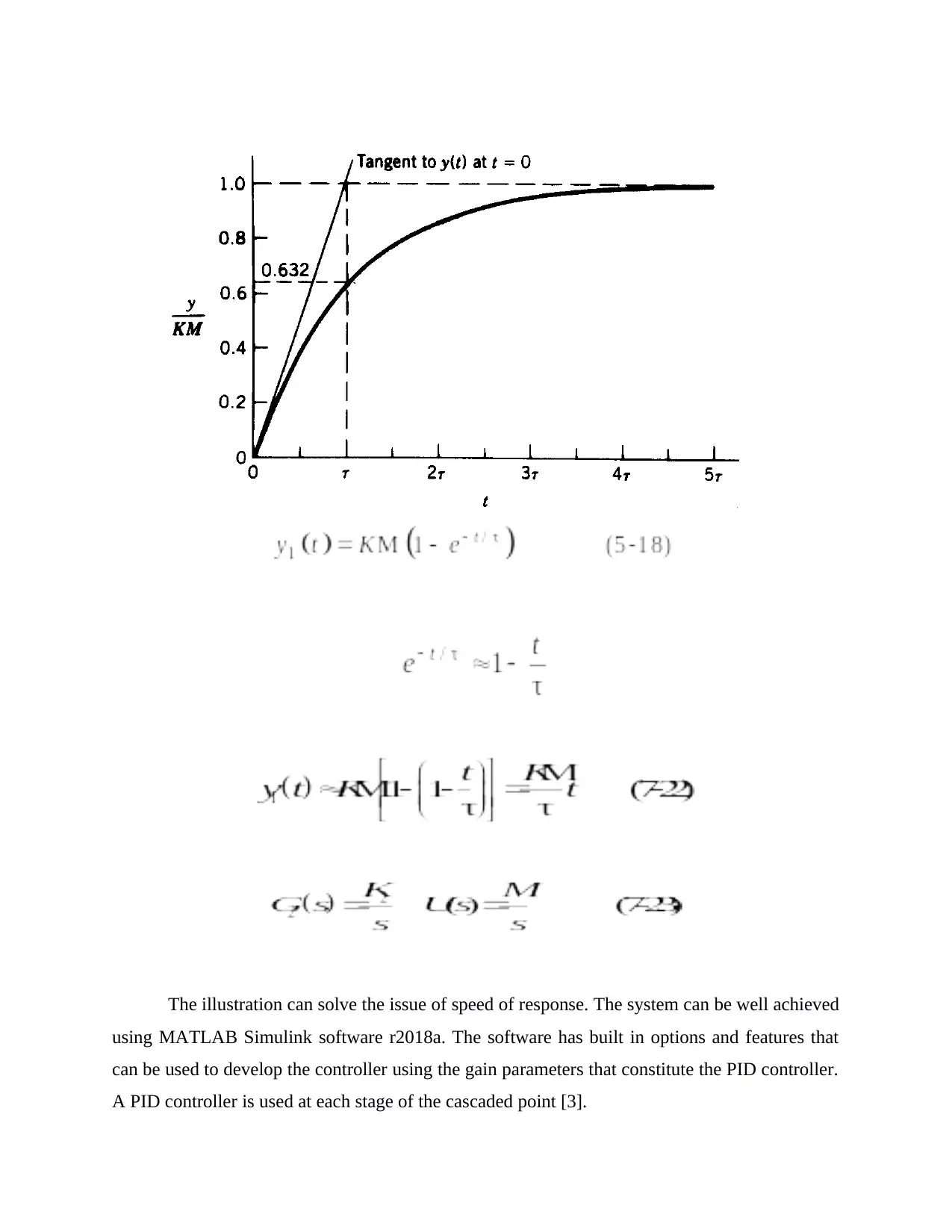
The graphical techniques employed to determine the basic first order system parameters
are the 63.2 percent response, point of inflection, s&k method, and the semilog plot.

Paraphrase This Document

Need a fresh take? Get an instant paraphrase of this document with our AI Paraphraser
Document Page
The illustration can solve the issue of speed of response. The system can be well achieved
using MATLAB Simulink software r2018a. The software has built in options and features that
can be used to develop the controller using the gain parameters that constitute the PID controller.
A PID controller is used at each stage of the cascaded point [3].
Document Page
Control strategy
a) Start:
b) Determine the system plant transfer function (first order system)
c) Determine the process variables, input variables, the measured and unmeasured variables,
as well as the sources of disturbance (external and internal)
d) Determine the most appropriate controller for the system which achieve the ultimate
control of the system (PID controller is most prevalent)
e) Implement it in block diagram or a MATLAB Simulink for illustration purposes
f) end:
ANALYSIS & MODELING
PID controller Vs. Cascaded architecture.
The PID controller as earlier highlighted is quite prevalent in a number of industrial
applications. It is implemented in systems that require to maintain system stability while
controlling the output in the presence of external disturbances. The controller requires a sensor
that monitors the output and sends back a feedback loop which measures the changes against the
disturbance variable. The controller is a feed forward implementation that requires proper
installation of the sensor to ensure that it measures the output and sends back the measurement to
the input section to ensure that the error is rectified and the expected output is yielded [4].
Document Page
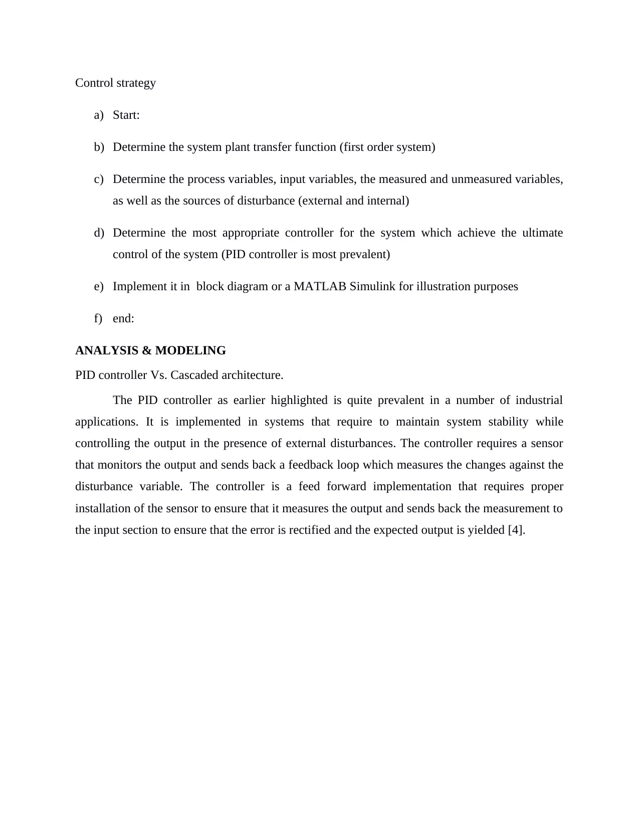
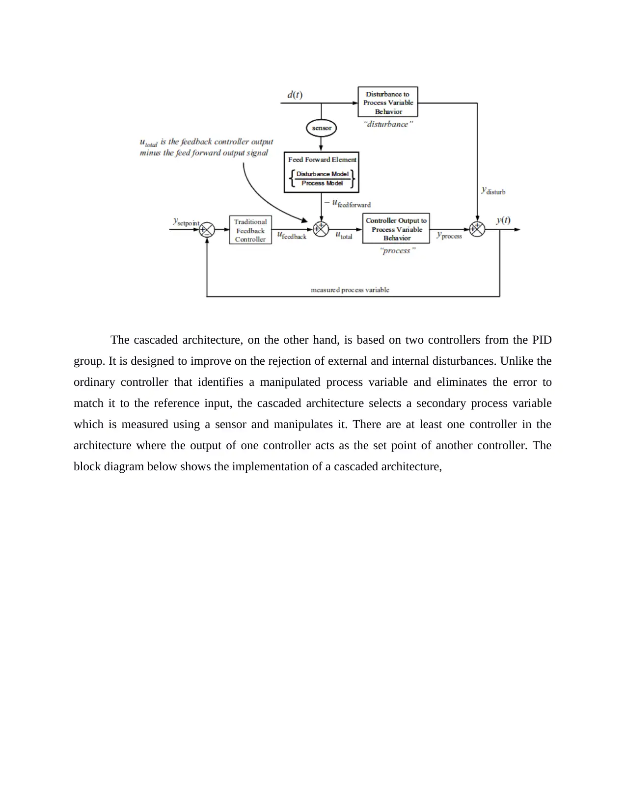
The cascaded architecture, on the other hand, is based on two controllers from the PID
group. It is designed to improve on the rejection of external and internal disturbances. Unlike the
ordinary controller that identifies a manipulated process variable and eliminates the error to
match it to the reference input, the cascaded architecture selects a secondary process variable
which is measured using a sensor and manipulates it. There are at least one controller in the
architecture where the output of one controller acts as the set point of another controller. The
block diagram below shows the implementation of a cascaded architecture,

Secure Best Marks with AI Grader

Need help grading? Try our AI Grader for instant feedback on your assignments.
Document Page
The cascaded architecture is preferred in case a secondary process variable is identified
and it needs to be controlled as well. I would use the cascaded architecture on this project
implementing two PID controllers to control the location of the optical sensor in terms of
calibration of the position and the dye connection valve regulation [5].
Safety is a great concern in industrial automation. The system must guarantee secure
operation of the system in dealing with the system such that human operators can manage it even
remotely from a control point. The controller equipment used should be cost-friendly such that
the designer uses the most efficient equipment that are pocket friendly. There are economic
considerations which are involved with cost considerations of the system as well as the
fabrication cost model used during large scale manufacture of the system. The use of the
controller should focus on creating a better environment especially where the controller is used.
The controller should use components which do not aggravate the environmental conditions. The
disposal of items after usage should also follow the environmental laws. Some nations require
one to dispose of electronic waste in designated centers. The proper implementation of the
controllers and disposal of the waste, thereafter, is carried out using the correct procedures as
stipulated by the environment regulation commissions in a given state.
CONCLUSION
Document Page
In a nutshell, it is possible to develop controllers for the system that injects dye for
clothes designs in the fashion industry. The system can be modeled using a feed forward
structure or a cascaded architecture based on the process variables. For this analysis, the
modeling proposes that one uses the cascaded architecture to control the two process variables
which could be used in determining the system stability. The project seeks to define the merits
and demerits of using a proportional, proportional-integral, and a proportional-integral-derivative
controller. The PID controller solves the issues that other controllers are unable to solve. It
guarantees optimum control dynamics to obtain zero steady state error, faster response which
implies a shorter rise time, no oscillations, no overshoots, and higher stability. The PID
controller achieve the ultimate control of a system and it is preferred to other controllers
especially when controlling a higher order system plant.
REFERENCES
[1]R. Farkh, K. Laabidi and M. Ksouri, "Robust PI/PID controller for interval first order system
with time delay", International Journal of Modelling, Identification and Control, vol. 13, no. 12,
p. 67, 2011.
[2]"ROBINAIR UV Dye Injection Kit - 1DZK9|16355 - Grainger", Grainger.com, 2018.
[Online]. Available: https://www.grainger.com/product/ROBINAIR-UV-Dye-Injection-Kit-
1DZK9. [Accessed: 11- Sep- 2018].
[3] TAGHERT, P. H., BASTIANI, M. J., HO, R. K. & GOODMAN, C. S. Guidance of pioneer
growth cones: Filopodial contacts and coupling revealed with an antibody to Lucifer Yellow.
Devl Biol. 94, 391-399, 2012.
[4] VANEY, D. I. Many diverse types of retinal neurons show tracer coupling when injected
with biocytin or Neurobiotin.Neuroscience Letters, 125, 187-190, 2009.
[5]WILLIAMS, D. A., FOGARTY, K. E., TSIEN, R. Y. & FAY, F. S. Calcium gradients in
single smooth muscle cells revealed by the digital imaging microscope using Fura-2.
Nature, Lond. 318,558-561, 2008.
1 out of 9
[object Object]

Your All-in-One AI-Powered Toolkit for Academic Success.

Available 24*7 on WhatsApp / Email

[object Object]