Dynamic Analysis Report: Blast Loading on I-Beam using FEA Methods

Verified

Added on  2022/08/01

|22
|1712
|30
Report
AI Summary
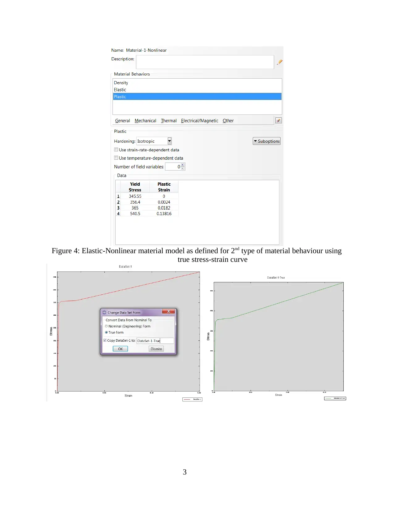
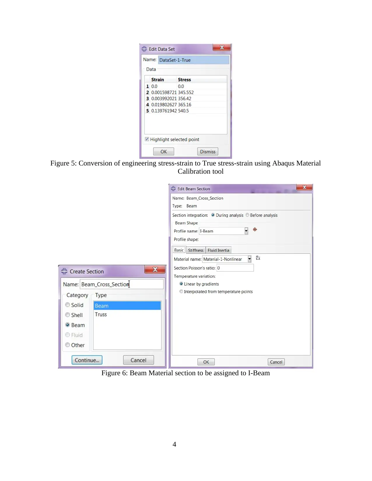
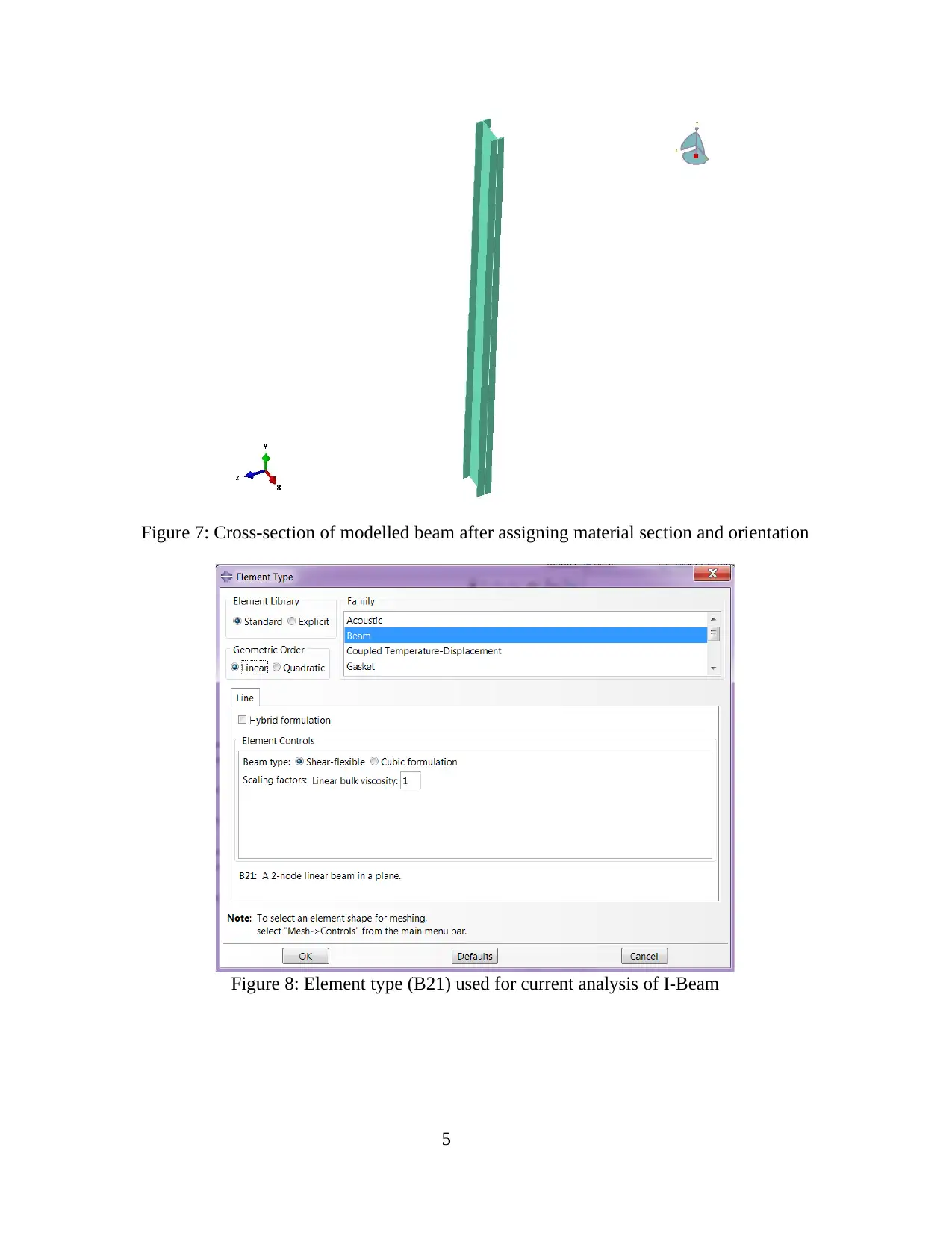
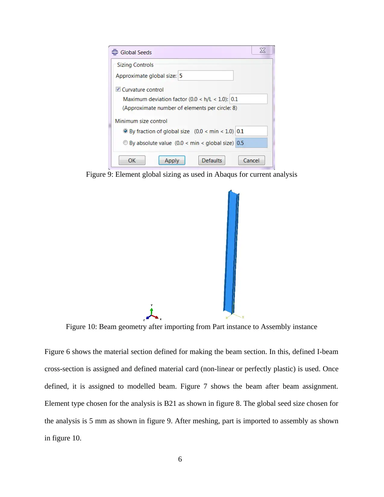
This report details a finite element analysis (FEA) of an I-beam subjected to blast loading, conducted using Abaqus. The study involves creating a non-linear dynamic FE model, defining material properties (linear-perfectly plastic and linear-nonlinear), and applying blast loads. The analysis explores different boundary conditions (one end pinned, both ends pinned) and investigates the impact of strain rate dependence on material behavior. The results include displacement and stress comparisons, as well as a comparison of reaction forces with Biggs data. The report compares the effectiveness of perfectly plastic versus non-linear material models. The study concludes with the observation that strain rate dependence has negligible effect. The report provides a detailed breakdown of the modeling process, results, and conclusions. The report is contributed by a student and is published on Desklib, a platform providing AI-based study tools and assignments for students.
Document Page
Dynamic Analysis using blast loading on an I-
Beam using Finite Element methods in Abaqus
<Student Name>
<Student Number>
Assignment Report
Supervisor: <XXX>
Department Name
University Name
<Month Year>
tabler-icon-diamond-filled.svg

Paraphrase This Document

Need a fresh take? Get an instant paraphrase of this document with our AI Paraphraser
Document Page
TABLE OF CONTENTS
TABLE OF CONTENTS..................................................................................................................i
TASK 1: Setting up non-linear FE Model.......................................................................................1
TASK 2: Results Of non-linear analysis and Comparison with Biggs-data..................................11
TASK 3: Results Of non-linear analysis with both ends pinned...................................................15
TASK 4: Using Strain rate dependence in Non-linear material.....................................................18
i
Document Page
TASK 1: Setting up non-linear FE Model
In Task 1, a non-linear dynamic FE model is to be prepared for blast wall stiffener beam with
several given inputs. The modelling steps for the model are described below. In figure 1,
Modeled geometry of beam along with I-beam cross-section is shown. This is modelled in
Abaqus as shown in figure 2. The length of the beam is 5150 mm as given in inputs.
Regarding material properties, 2 different types of material models are to be used. First is, linear-
perfectly plastic for which only yield strength of material is to be defined, it is shown in figure 3.
Second is, linear-nonlinear for which non-linear relationship between stress and strain post yield
point is necessary, it is shown in figure 4. The provided engineering stress-strain data is
converted into true stress-strain data using Abaqus material calibration as shown in figure 5.
Figure 1: Dimensions of beam and I Cross-section to be modelled
1
Document Page
Figure 2: I-Beam Cross-section Dimensions as used in Abaqus modelling
Figure 3: Elastic-Perfectly plastic material model as defined for 1st type of material behaviour
2
tabler-icon-diamond-filled.svg

Paraphrase This Document

Need a fresh take? Get an instant paraphrase of this document with our AI Paraphraser
Document Page
Figure 4: Elastic-Nonlinear material model as defined for 2nd type of material behaviour using
true stress-strain curve
3
Document Page
Figure 5: Conversion of engineering stress-strain to True stress-strain using Abaqus Material
Calibration tool
Figure 6: Beam Material section to be assigned to I-Beam
4
Document Page
Figure 7: Cross-section of modelled beam after assigning material section and orientation
Figure 8: Element type (B21) used for current analysis of I-Beam
5
tabler-icon-diamond-filled.svg

Paraphrase This Document

Need a fresh take? Get an instant paraphrase of this document with our AI Paraphraser
Document Page
Figure 9: Element global sizing as used in Abaqus for current analysis
Figure 10: Beam geometry after importing from Part instance to Assembly instance
Figure 6 shows the material section defined for making the beam section. In this, defined I-beam
cross-section is assigned and defined material card (non-linear or perfectly plastic) is used. Once
defined, it is assigned to modelled beam. Figure 7 shows the beam after beam assignment.
Element type chosen for the analysis is B21 as shown in figure 8. The global seed size chosen for
the analysis is 5 mm as shown in figure 9. After meshing, part is imported to assembly as shown
in figure 10.
6
Document Page
Figure 11: Load step of Explicit Dynamic as created in Abaqus for Solution with 30 micro
seconds as total simulation time
Figure 12: Loading amplitude as created in Abaqus to replicate the loading and unloading cycle
in 10 microseconds
7
Document Page
Figure 13: Pinned Boundary condition as applied on bottom node of I-Beam
Figure 14: Sliding Boundary condition as applied on top node of I-Beam
Figure 11 shows explicit dynamic step that is created in Abaqus with 30 micro second total time.
No mass scaling is used in the analysis. Figure 12 shows the amplitude created to define the
increase and decrease of peak load in 10 micro seconds each. The calculated load for both the
pressure 1.05 and 2.1 bar is shown in Table 1 and Table 2. Pinned and sliding boundary
8
tabler-icon-diamond-filled.svg

Paraphrase This Document

Need a fresh take? Get an instant paraphrase of this document with our AI Paraphraser
Document Page
condition defined is shown in figure 13 and 14. Final model after loads and boundary conditions
definition is shown in figure 15.
Figure 15: I-Beam geometry after applying loads and boundary conditions
Table 1: Calculation of Line load for application on I Beam for 1.05 Bar
Peak Pressure 1.05 bar
Width 1000 mm
Length 5150 mm
Peak Load 540750 N
Uniformly Distributed load 105 N/mm
Table 2: Calculation of Line load for application on I Beam for 2.10 Bar
Peak Pressure 2.1 bar
Width 1000 mm
Length 5150 mm
Peak Load 1081500 N
Uniformly Distributed load 210 N/mm
9
Document Page
Justification for choosing current modelling method –
The Beam modelling method in Abaqus is quite accurate and many benchmark studies have been
performed as available in literature where it has been proven that for simpler problems, 1D beam
modelling approach is found to be nearly accurate with certain assumptions.
The choice of linear element is justified by the fact that the mesh convergence study is
performed. Choosing non-linear elements does not change the results hence linear elements are
chosen. Mesh density is justified again with mesh convergence study.
10
chevron_up_icon
1 out of 22
circle_padding
hide_on_mobile
zoom_out_icon