Ask a question from expert
Dynamic System Modelling of a Motor Bike
17 Pages2333 Words216 Views
Added on 2020-02-18
Dynamic System Modelling of a Motor Bike
Added on 2020-02-18
BookmarkShareRelated Documents
ABSTRACT This paper seeks to discuss the second degree of freedom dynamic system modelling ofa motor bike. The key software used for analysis is the MATLAB software. Damping is vital inpreventing the uncontrollable oscillation of the system about its equilibrium point. Most of themotorbikes are used to race on solely flat surfaces but others are exposed to uneven terrain. Thisis done to ensure that the motorbike does not only survive good straight-line speed and ensuresthat it can corner in a quick and safe manner. While operating in straight motion, the mainfunction of the suspension geometric system is to separate the unsprang mass. The mass definesthe chassis and rider from any road irregularities. This is accomplished using a soft set up withlow stiffness. For instance, if the motorbike encounters a bump in the road, the suspension iscompressed and the rider notices little or no discomfort, then the suspension or shock absorbersare said to be intact. Former engineering designs may not have successfully accomplished tosolve the issue of a motorbike having to speed from straight line of motion to negotiating a sharpbend. The flaw in the design leads to a suspension which is flexible in almost all directions asituation which affects lateral stability[ CITATION Cos02 \l 1033 ]. Unfortunately, the single DOF indynamic modelling does not adequately model all the systems.
TABLE OF CONTENTSABSTRACT................................................................................................................................................1INTRODUCTION AND ASSUMPTIONS.................................................................................................3Introduction.............................................................................................................................................3Assumptions............................................................................................................................................4FREE VIBRATION RESPONSE................................................................................................................4(i)Schematic diagram of free vibration................................................................................................4(ii)Free body diagram of free vibration.............................................................................................4(iii)Equation of motion as per newton’s second law of motion..........................................................4(iv)Discussion....................................................................................................................................6FORCED VIBRATION RESPONSE..........................................................................................................7(i)Schematic diagram of forced vibration and free body diagram of free vibration.............................7.................................................................................................................................................................7(ii)Equation of motion as per newton’s second law of motion..........................................................7(iii)Discussion....................................................................................................................................8ANALYSIS.................................................................................................................................................8MAGNIFICATION AND TRANSMISSIBILITY FACTOR......................................................................8MODELLING THE SYSTEM IN SIMULINK.........................................................................................11(iii)Minimum Scope: Reflection and Discussion.................................................................................14CONCLUSION.........................................................................................................................................18REFERENCES..........................................................................................................................................18
INTRODUCTION AND ASSUMPTIONSThe free body system of a motorbike in the second degree of freedom, has the followingdynamic system modelling.The values used in the calculations for this assignment were stipulated in the previous projectwhile tackling the single DOF tasks. The systems that require two independent coordinates todescribe their motion are called the two degree of freedom systems. Assumptions(a)The system has second degree of freedom.(b)The springs and dampers are not fault and do not experience any drag.(c)The resistance force is neglected
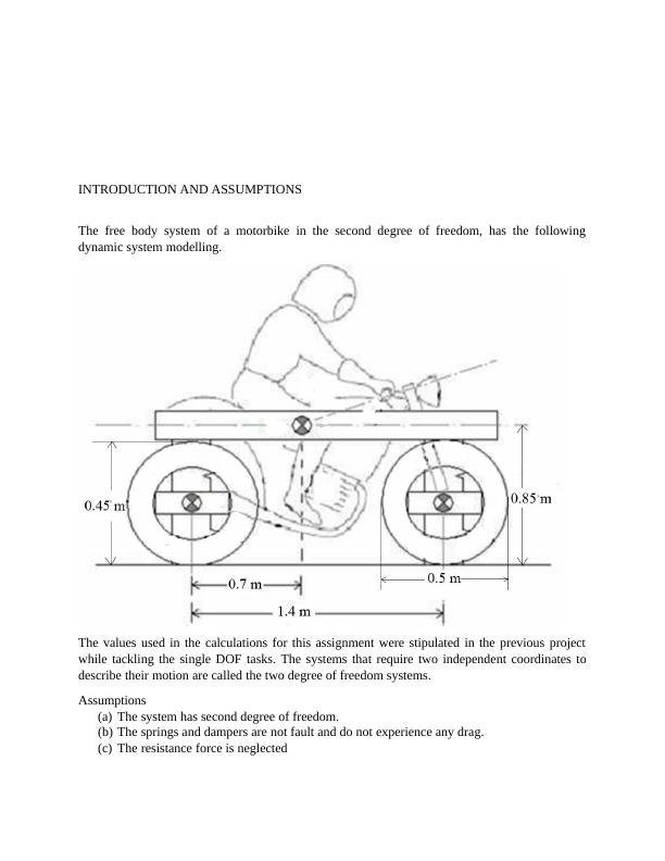
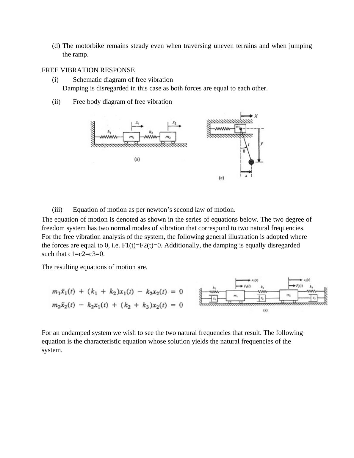
(d)The motorbike remains steady even when traversing uneven terrains and when jumpingthe ramp.FREE VIBRATION RESPONSE(i)Schematic diagram of free vibrationDamping is disregarded in this case as both forces are equal to each other.(ii)Free body diagram of free vibration(iii)Equation of motion as per newton’s second law of motion. The equation of motion is denoted as shown in the series of equations below. The two degree offreedom system has two normal modes of vibration that correspond to two natural frequencies. For the free vibration analysis of the system, the following general illustration is adopted where the forces are equal to 0, i.e. F1(t)=F2(t)=0. Additionally, the damping is equally disregarded such that c1=c2=c3=0. The resulting equations of motion are,For an undamped system we wish to see the two natural frequencies that result. The following equation is the characteristic equation whose solution yields the natural frequencies of the system.
End of preview
Want to access all the pages? Upload your documents or become a member.
Related Documents
Magnification Factor and DOF simulation- Projectlg...
|25
|3505
|357
MECH3422 - Dynamic System Modelling and Controllg...
|10
|1352
|258
ENEM14015 - Dynamic System Modelling and Controllg...
|24
|2963
|176
Application of Mechanical Control for Quad Bike: ENEM20001lg...
|20
|1928
|280
AMME3500 SYSTEMS DYNAMICS AND CONTROL.lg...
|20
|3316
|1
ENEM14015 - Dynamic System Modelling and Control | Assignmentlg...
|10
|1212
|245