The Contribution of DYNAMO Visual Programming Software in the Evolution of BIM
VerifiedAdded on 2022/08/20
|50
|19073
|28
AI Summary
Contribute Materials
Your contribution can guide someone’s learning journey. Share your
documents today.
DYNAMO and BIM
THE CONTRIBUTION OF DYNAMO VISUAL PROGRAMMING SOFTWARE IN THE
EVOLUTION OF BIM
Table of Contents
THE CONTRIBUTION OF DYNAMO VISUAL PROGRAMMING SOFTWARE IN THE
EVOLUTION OF BIM................................................................................................................1
1. Introduction to the study...................................................................................................2
1.1. Background...................................................................................................................3
1.2. Purpose..............................................................................................................................5
1.3. Goal...................................................................................................................................6
1.4. Limitations........................................................................................................................6
2. LITERATURE REVIEW.....................................................................................................6
2.1. Definition and history of Building Information Modelling (BIM)...................................6
2.1.1. The current state of Building Information Modelling (BIM)........................................7
2.1.2. Conditions to be met so as to qualify as a BIM model..................................................9
2.1.3. The value of BIM in the context of building design.....................................................9
2.2. Autodesk Revit..................................................................................................................9
2.2.1. The History of Revit......................................................................................................9
2.2.2. Configurations in Revit...............................................................................................11
1. Model elements...................................................................................................................11
iii. Datums.........................................................................................................................12
2. View-specific elements.......................................................................................................12
3. Views..................................................................................................................................12
2.2.3. The Revit Hierarchy....................................................................................................13
2.3. Dynamo Visual Programming Software.........................................................................15
2.3.1. The concept of Visual programming...........................................................................15
2.3.2. Dynamo Visual Programming Software.....................................................................16
2.3.3. The value of Dynamo Visual Programming Software in Revit..................................17
2.4. Object-oriented Programming.........................................................................................18
2.5. Application Project Interface (API)................................................................................19
Chapter 3........................................................................................................................................20
1
THE CONTRIBUTION OF DYNAMO VISUAL PROGRAMMING SOFTWARE IN THE
EVOLUTION OF BIM
Table of Contents
THE CONTRIBUTION OF DYNAMO VISUAL PROGRAMMING SOFTWARE IN THE
EVOLUTION OF BIM................................................................................................................1
1. Introduction to the study...................................................................................................2
1.1. Background...................................................................................................................3
1.2. Purpose..............................................................................................................................5
1.3. Goal...................................................................................................................................6
1.4. Limitations........................................................................................................................6
2. LITERATURE REVIEW.....................................................................................................6
2.1. Definition and history of Building Information Modelling (BIM)...................................6
2.1.1. The current state of Building Information Modelling (BIM)........................................7
2.1.2. Conditions to be met so as to qualify as a BIM model..................................................9
2.1.3. The value of BIM in the context of building design.....................................................9
2.2. Autodesk Revit..................................................................................................................9
2.2.1. The History of Revit......................................................................................................9
2.2.2. Configurations in Revit...............................................................................................11
1. Model elements...................................................................................................................11
iii. Datums.........................................................................................................................12
2. View-specific elements.......................................................................................................12
3. Views..................................................................................................................................12
2.2.3. The Revit Hierarchy....................................................................................................13
2.3. Dynamo Visual Programming Software.........................................................................15
2.3.1. The concept of Visual programming...........................................................................15
2.3.2. Dynamo Visual Programming Software.....................................................................16
2.3.3. The value of Dynamo Visual Programming Software in Revit..................................17
2.4. Object-oriented Programming.........................................................................................18
2.5. Application Project Interface (API)................................................................................19
Chapter 3........................................................................................................................................20
1
Secure Best Marks with AI Grader
Need help grading? Try our AI Grader for instant feedback on your assignments.
DYNAMO and BIM
Methodology..................................................................................................................................20
Chapter overview.......................................................................................................................20
Building information modeling notion......................................................................................20
Brief history of BIM..................................................................................................................20
BIM dimension..........................................................................................................................21
Visual programming essentials..................................................................................................22
Dynamo......................................................................................................................................23
Dynamo user interface...............................................................................................................23
Dynamo and Revit.....................................................................................................................24
Starting Dynamo........................................................................................................................25
Experimental methodology........................................................................................................26
Methods......................................................................................................................................26
Details of the dynamo script...................................................................................................26
Elements placement................................................................................................................26
The case study............................................................................................................................27
Application designing................................................................................................................29
Existing groups..........................................................................................................................35
Summary of the chapter.............................................................................................................40
Chapter 4........................................................................................................................................41
Results............................................................................................................................................41
The chapter overview.................................................................................................................41
Experimental results...................................................................................................................41
Discussion of the results............................................................................................................41
Parameterization in BIM models...............................................................................................42
Chapter 5........................................................................................................................................43
Conclusion and Recommendation.................................................................................................43
Conclusion.................................................................................................................................43
Recommendation to the study....................................................................................................44
List of reference.............................................................................................................................44
2
DYNAMO and BIM
1. Introduction to the study
This chapter outlines the background, purpose, aims and limitations of this thesis.
1.1. Background
Currently in the world of architectural engineering, civil engineering and general construction, a
lot of emphasis is being given to time saving abilities; as such, engineers are under a lot of
pressure to save time while also delivering quality and precise work. In order to be able to
deliver the requisite standards of work at the shortest time possible, engineers need to apply a
wide range of methods and tools. Luckily enough due to the wonders of technology such
methods and tools are abundantly available (Singh, 2017). Over the last couple of years, several
construction companies have taken drastic efforts towards automating the work of their
architectural engineers and civil engineers and as such they have moved from hand drawings to
using computer software and BIM (Sacks & Pikas, 2013). The term BIM is an acronym for
Building information modelling which refers to an intelligent three dimensions model- founded
process that is usually used by architectural engineers and other professionals within the
construction and engineering fields to generate in-depth insights and tools for more efficient
planning, designing, constructs and perfect management of buildings and other forms of
infrastructure (Thomson, 2016) .
In recent times, the computing capabilities that are used to epitomize and analyse three-
dimensional models for buildings has improved drastically. The recent advent and evolution of
Building Information Modelling (BIM) has drastically transformed the Architectural,
Engineering and general construction fields from a drawing-based, Computer Aided Design
(CAD) sector to a fully-fledged management and transfer of information-based industry. The
increasing demand for proficiency and time saving during the process of constructing buildings
has stimulated the civil engineering, architectural and general construction industry towards the
full exploitation of the possibilities offered by the current tech-based advancements in the field
of structural design (Kranz, 2016). Various facets of structural design that include but are not
limited to geometrical simulations, performance analysis, mathematical optimization and even
the process of automation have begun to revolutionize the construction industry by inadvertently
arousing attention towards cutting edge techniques of modelling and testing building designs
inside virtual backgrounds (Chi & Wang, 2013). At the moment, the architectural industry
prompts the comprehension behind digital tech-based models by recognising three-dimensional
modelling not only as an exemplification of the actual building but also as a virtual model that is
used to test the actual state of affairs and reclaim crucial information that will aid in achieving
the requisite proficiency that is demanded for by all shareholders (Gamil, 2017). The more
enhanced and effectual these simulations are along the preliminary phases of design, the grander
the possibility for general realization of the project’s goals.
3
DYNAMO and BIM
The progressive advancements in automation have led to the development of parametric design
which refers to the application of visual programming software which in essence, is directly
connected to the main BIM software (Borland, 2019). In attempts to achieve greater targets of
simulation reliability, efficiency and quality standards, parametric modelling has upheld itself
has one of the most effective tools. Parametric modelling facilitates the creation of malleable and
adjustable designs that can be pooled together with analysis, optimization and computation tools
(Garber, 2017). As such, it raises the overall efficiency of the building model. Furthermore, at
the moment these tools have the ability to integrate Building Information Modelling (BIM)
backgrounds, thereby creating room for more evolved and advanced applications. Although the
application of Virtual Programming software such as Dynamo, Grasshopper and Rhino in the
architectural, civil engineering and general construction fields is still at an all-time low, it is also
factual to argue that more and more investors in the aforementioned industry have become
conscious to the prospective advantages that they would reap by making use of Virtual
Programming software (Holzer, 2016). Moreover, the application of parametric modelling is
drastically increasing due to the fact that more and more countries are in the process of
establishing and enforcing new laws that require mandatory BIM application in particular sets of
projects (de Mattos Nascimentoa, 2016).
The application of visual programming software in BIM has played a very huge role in the
evolution of Building information modelling (BIM). The concept of “Visual Programming
Language” enables designers to construct very realistic relationships using graphical user
interfaces. Instead of developing programming ‘code’ from scratch, the users of visual
programming software can be able bring together conventional associations by connecting pre-
packaged nodes together to make up a complete traditional visual programming algorithm
(Meža, & Dolenc, 2015). Basically, this means that by using visual programming language, a
designer can be able to leverage computational concepts without necessarily having to write new
programming codes (Marcos, 2018). Computational design frameworks such as Visual
Programming software grant users the requisite resources and abilities for systematic automated
geometry creation, alteration and regulation of family parameters using external data and
information dissemination within a given platform and between different design platforms.
Computational design is a term used to refer to the ability to tie creative techniques of solving
problems with powerful and novel computational algorithms that have the ability to program,
mimic, script, regulate and produce various design solutions (Borges, 2018). In recent years,
computational Design has had a massive influence on Architectural endeavours. Design exploits,
be it hefty or minor, have begun to demand for new computational capabilities that allow
architectural engineers to customize their practices and perhaps, pursue cutting edge, innovative
design programs (Nemirovsky, 2017). Computations such as the use of Visual programming can
be leveraged for different for example, architectural engineering design, and the automation of
redundant production process and the construction of expressive form-generators. Irrespective of
the application of computation, it is very clear that designers need frameworks that can enable
4
Secure Best Marks with AI Grader
Need help grading? Try our AI Grader for instant feedback on your assignments.
DYNAMO and BIM
them to carry out their tasks with easily, more efficiently and within the shortest possible time
(Weinberg, 2019).
At the moment, Dynamo visual programming software is the leading software in the realm of
architectural design and as such is regarded as the leading driver of BIM evolution. Dynamo
visual programming software is an open source Add-in for Autodesk Revit and Vasari which
enables architectural designers to design conventional computation-based designs and
automation processes by making use of a node-based Visual Programming Interface (Cantrell,
and Mekies, 2018). Dynamo Visual Programming software gives architectural designers the
capabilities of sophisticated data manipulation, absolute geometric regulation and relational
frameworks all of which are impossible to achieve using traditional modelling interfaces. On top
of that, Dynamo Visual Programming software grants any architectural designer the surplus
advantage of the ability to leverage computational design workflows within the perspective of a
BIM background, as such; the user is gifted with the ability to construct conventional systems to
regulate Vasari families and constraints (Dutt and Swartz, 2016). In summary, it would be
correct to say that Dynamo Visual Programming software brings out a new essential means in
which architectural engineering designers can work with geometric information within Autodesk
Vasari and Revit towards creating regulatory frameworks for developing, arranging and
visualizing various geometrical concepts (Veloso and Scheeren, 2018). Basically, the Dynamo
Visual Programming framework enables architectural designers to come up with unique systems
and associations that have expanded individual perceptions on how BIM can be used to drive
design ideation.
In summary, it is correct to argue that design ideation through the use of Building Information
Modelling (BIM) is driven towards greater heights by parametric design tools which are based
on 3D CAD software such as Revit which serve to lengthen the margin of potential of BIM. On
top of that, tools like Revit create room for extensive customization capabilities via a set of add-
ins that extend BIM’s native capabilities. In most cases, this add-ins are technologically
advanced by third parties, thus creating room for the integration of performance simulations that
support several interoperability systems such as the Building Information Modelling (BIM)
system whose role is then to solve design complications using optimization techniques, and has
the capability to considerably automate design processes (Bazafkan, 2017). The integration of
Virtual Programming tools on BIM not only instils the Building Information Modelling (BIM)
system with great tractability but also the requisite malleability to be made use of on the
immense majority of projects from the architectural, civil engineering and general construction
industry.
1.2. Purpose
The purpose of this research is to illustrate the contribution of Dynamo Visual Programming
Software in the evolution of Building information modelling (BIM). As mentioned earlier,
construction companies are constantly striving towards reducing the time taken to complete their
projects while also seeking to improve the quality of their work. This endeavour has led to the
5
DYNAMO and BIM
development of new technologies, products and highly advanced ways of thinking within the
realm of architectural engineering and general construction. This thesis is meant to demonstrate
the contribution that Dynamo Visual Programming software has had on the evolution of BIM
through the aforementioned software’s ability to come up with cutting edge possibilities for
efficient and state of the art modelling and tabulation of BIM models.
1.3. Goal
This thesis aims to illustrate the ways in which Dynamo Visual Programming software has
contributed in the evolution of Building information Modelling (BIM). Despite the fact that
Visual Programming has been widely made use of in different fields, this paper acknowledges
that it has only recently developed significance in the 3D modelling programs of architectural,
civil engineering and general construction fields. Considering the fact that Visual Programming
software are relatively new in the building industry, the goal of this paper is to look at the
various aspects of Dynamo Visual Programming Software that make it a very vital contributor to
the evolution of Building Information Modelling (BIM). Currently, there are numerous
construction companies operating within the construction industry and they use a wide variety of
software throughout the construction process. There is a wide variety of software which could be
used for modelling, energy calculations and calculations of load paths. This research is not meant
to downplay the role of other Visual Programming software but to undoubtedly bring out the role
that Dynamo Visual Programming software plays in the evolution of BIM compared to other
Visual Programming software such as, Grasshopper Visual Programming software and Rhino
Visual Programming software. The analytical applications that are materialized in this thesis
help to demonstrate the enormous possibilities that Dynamo Visual Programming software has
towards completing and improving Building Information Modelling (BIM) as a result of the fact
that it includes parametric geometries and works with Rivets which is basically, the foremost
BIM software.
1.4. Limitations
The exploration of the contribution of Dynamo Visual Programming software in the evolution of
Building Information Modelling (BIM) will be the main area of concern for this research.
Although Dynamo Visual Programming Software cannot be the only Visual Programming
software that is credited for the evolution of BIM, this thesis aims to limit itself to the Dynamo
Visual Programming software purview. The script of the research will be limited to the
aforementioned goals of the thesis. Putting the topic at hand into consideration, several case
studies can be necessary however; this thesis will comprise the generalization of the key aspects
of the Dynamo Visual Programming software with regard to BIM and analysis of Dynamo
Visual Programming elements that are perceived to drive the evolution of Building Information
Modelling (BIM).
2. LITERATURE REVIEW
In this chapter, the theoretical framework of the key aspects behind this thesis is described and
an in-depth explanation is given as to why the aforementioned aspects are important to this work.
6
DYNAMO and BIM
Furthermore, this chapter will take an in-depth look into the dynamo Visual Programming
software and its relationship with Revit and BIM as a whole.
2.1. Definition and history of Building Information Modelling (BIM)
Building Information Modelling (BIM) is a term used to refer to the procedure that is used to
create a three-dimensional model platform that lets design professionals such as architects and
civil engineering consultants to partake in the design process on an immediate and
multidisciplinary basis (Mayo and Smith, 2018). The concept of BIM is relatively new in the
arena of architecture, civil engineering and general construction but it is true to say that at the
moment, building information modelling (BIM) has been attracting a lot of attention in the
architectural, civil engineering and general construction fields. Within the last half of the decade
alone, the world has been spouting about BIM in the architectural, building and construction
fields so much that most countries are currently in the process of enacting laws and regulations
that will make the application of BIM compulsory in certain projects (Sieffert & Daudon, 2014).
BIM has been the trending catchphrase in the realm of architecture, civil engineering and general
construction and though it may appear to be new to most people, in actual sense the concepts and
technologies behind BIM have been in existence and constantly evolving for more than five
decades MANJUNATHA, 2019).
In retrospect, the idea behind the existence of BIM cannot be credited to a single individual
mainly because it has a very rich history of origination from various regions in the world
including the United States of America (USA), Central and Northern Europe and across the seas
to Japan which is situated in Asia. Basically, the concept of BIM has been in existence since the
advent of the 1970s (De Wilde and Garrigós, 2019). However, it was not until the middle of the
1980’s that the term “building model” was placed in print by a man known as Simon Ruffle.
Nearly a decade later, the term “Building Information Model” was coined and published by G.A.
Van Nederveen alongside a colleague known as F. P. Tolman in 1992. After the term ‘BIM’ was
coined, its development and evolution began officially but no significant leaps were taken until
construction and architectural companies changed their design systems from hand drawings to
AutoCAD digital drawings. AutoCAD’s 2D drawings are mostly similar to hand drawings but
the only difference is that they are done faster. The next step in the evolution of building design
was the introduction of BIM (Nikolic, & Messner, 2011). By making use of a wide variety of
computer software such as Revit, Tekla structures and numerous other types of software, the
users can be able to come up with various distinct shapes and designs within the software’s
framework in a very easy manner. From the 3D models that are generated by the software, 2D
printed drawings can then be acquired. Looking back at the history of BIM, one would
fascinatingly notice that a huge chunk of its history is entangled with the drama of the Cold War.
In summary, it would be true to argue that all these pleasing tales about the innovation and the
evolution of BIM come down to the sprint towards coming up with the most flawless collective
solution that would upset the 2D CAD work flows.
7
Paraphrase This Document
Need a fresh take? Get an instant paraphrase of this document with our AI Paraphraser
DYNAMO and BIM
2.1.1. The current state of Building Information Modelling (BIM)
Currently, the most idyllic BIM software has capability to epitomize the actual physical and
inherent features of a building as an object-focused design that is linked to a particular database.
Most modern Building Information Models have the ability to render contraptions, enhance
property specific categorization and program specific backgrounds from which designers can be
able to build model components. Furthermore, modern BIM models are mostly three-
dimensional in nature with orthographic two-dimensional plans that are made up of sectional and
elevation outlooks (Shigaki, 2016). During the course of infrastructural or architectural project
development, project representations and variations are congruently adjusted with each change in
the design. Building information models can be designed within software that may or may not be
parametric in nature but it is important to note that the best Building Information Models are
those that are designed within parametric software frameworks. The most recent versions of
BIM have the capability to handle enormous volumes of information, hence the need for
parametric software. In its current form, BIM can be able to make use of a wide variety of files
key among them being the Industry Foundation Classes (IFC) files (Johansen and Kjærvik,
2018). Industry Foundation Classes refers to open and neutral data file formats that can be
opened through various platforms such as Revit. It is also important to note that IFCs exist on a
read-only format and therefore, cannot be edited under any circumstances whatsoever (Becerik-
Gerber, & Ku, 2011). However, despite the fact that IFCs cannot be edited, they can be
influenced on a certain level using Dynamo Visual Programming Software.
An in-depth look into literature concerned with Building Information models reveals that
parametric software are vital for the ultimate efficiency and quality of any given BIM system.
Parametric can be defined as an algorithm-based method that gives room for the manifestation of
parameters and regulations that, collectively serve to delineate, encrypt and elucidate the
relationship between the intention of the model and the model’s subjective response (Wang,
2014). The role of parametric software in regards to BIM is to provide capabilities for the
generation of constraint features which include the elevation of a horizontal base, which then can
be connected to the elevation of a particular set of walls which are parametrically placed in tune
with each other thereby, forming a geometry-linked dynamic database design. The evolution of
BIM as a result of its integration with parametric software introduced a cutting-edge solution to
the challenge of absence of computable raw data during the design stage of any architectural,
civil engineering or general construction project.
The introduction of parametric modelling in BIM created the much needed room for the
architectural, civil engineering and general construction industry to change project
representations at several scales and across disjointed sketch sheets thereby, reducing in a major
proportion the long and tiresome hours that were necessary for manual redrafting of the sketches
(Högberg and SPARGREN, 2017). The application of computer-based technology in the design
sector led to extensive automation of time consuming tasks in all disciplines, thereby largely
improving general yield. During its initial discovery stages, BIM was more of a grammatical
8
DYNAMO and BIM
term than actual useful technology. As time went by, BIM evolved and computer limitations and
weird user interfaces for BIM platforms ended up with 2D line drawing programs such as
AutoCAD (Nawari, 2012). It took quite a significant amount of time to incorporate
computability in design modelling.
2.1.2. Conditions to be met so as to qualify as a BIM model
Currently, there are four conditions that must be met in order to refer to a model as BIM and they
include:
Management of information is carried out basing on one or more object-oriented models.
Features are linked to the objects in the models and are applied extensively.
The bits and pieces that make up the model are associated to each other.
A wide variety of views of information can be formed from the same model.
2.1.3. The value of BIM in the context of building design
It is a universally accepted fact that it is extremely expensive to put up buildings. Furthermore,
there is a deep rooted consensus that what makes the construction of the aforementioned
buildings that much expensive is the cost that comes with the design stage which is actually more
expensive than it should just fully be. Thanks to the invention of Building information models,
professionals in the building industry have found it much easier to come up with building models
within a computer. The models are digital in nature therefore making the computer-based models
of building more convenient and much cheaper than hand drawings which were used before BIM
was introduced to the building industry. The process of coming up with a building is made up of
an entire lifespan of the building in question ranging from its idea, design stage, construction,
serviceable life, remodelling and perhaps its disposal and it is important to note that BIM can be
very instrumental in all parts of the aforementioned stages of a building’s lifecycle (Madanayake
and Egbu, 2017).
2.2. Autodesk Revit
Autodesk Revit is essentially a building information modelling software that is used by a wide
variety of design professionals ranging from building architects, backdrop architects, structural
engineering practitioners, mechanical engineers, electrical engineers and plumbing engineers,
general designers and building contractors among others (Li, 2018). Revit Autodesk 3D
modelling software allows its users to design an extensive variety of aspects of a structure in a
manner that the designer or the architect can be able to envisage the whole structure before
transforming the different sections of the design into a drawing on a hard copy. After generating
a 3dimensional design it is then printed onto a paper in 2 dimensional formats which the
contractor can later use during the actual construction stage. Basically, the role of Revit is to
design various structures and organize their components in three-dimensional formats, interpret
the model with two-dimensional drafting features and access buildings’ raw data from the
building design's database (Sacks and Teicholz, 2018).
9
DYNAMO and BIM
2.2.1. The History of Revit
The story of Revit began in 1997 the month of October with the foundation of Charles River
Software Company by Leonid Raiz and Irwin Jungreis in Newton the state of Massachusetts,
United States of America. Leonid Raiz and Irwin Jungreis were the main developers of cutting-
edge Engineering software for mechanical modelling and their goal in forming Charles River
Software Company was to transfer the power of parametric design to the architectural, civil
engineering and general construction industry (Yadav and Kanade, 2018). Leonid and Irwin
adequately utilized the funding that they received from venture capitalists known as Atlas
Venture and North Bridge Venture Partners towards hiring a very robust team of software
developers and architects. The collective team of specialist began their jobs by developing Revit
in C++ on window’s Microsoft platform. By the year 1999, they had hired a company CEO
known as Dave Lemont and also recruited two board members known as Jon Hirschtick and Arol
Wolford who were founders of Solidworks and CMD group respectively (.
From its onset, the intended purpose of Revit was to give room for various professionals such as
architects and building practitioners to create models and representations of an actual building by
coming up with parametric three-dimensional designs that are made up of non-geometric and
geometric models and construction raw data which are also referred to as Building Information
Modelling (BIM). At that particular point in time, a wide variety of other software packages for
example, ArchiCAD and Reflex had already been introduced into the market. ArchiCAD and
Reflex were able to generate 3D models and grant their users the ability to regulate individual
features through various parametric components. The two main variations between the
functionality of Revit and that of ArchiCAD and Reflex at that particular point in time were that
in Revit were that its users were able to create parametric components in a graphical ‘family
editor’ format instead of using a programming language. As such, the design adopted the
association between various components, perceptions and interpretations in a manner that will
enable the system to automatically disseminate a change in one element so as to maintain the
consistency of the model (Imtaar, 2016). For instance, if one were to move one wall the rest of
the adjacent walls will be automatically updated such that the model will remain interlinked and
all the relevant documentations will remain coordinated. Also, the concept of dual directional
association amongst various parametric components, perceptions and interpretations was one of
the main distinguishing features between Revit releases and other related software packages at
that particular point in time. The ease of making a wide variety of changes during the design
stages of the structures drove the company towards adopting the name Revit which is basically a
contraction of Revise Instantly (Takim & Nawawi, 2013). A parametric change transmission
engine is found at the heart of Revit and was mostly relied upon as a cutting-edge technological,
perspective driven parametric system that was found to be more scalable compared to the
change-based, history driven parametric systems that were applied in mechanical CAD software.
As such, the term ‘Parametric Building Model’ was coined to mirror the fact that the ability to
alter different parameters led to the subsequent evolution of the entire building model alongside
related documentations (Danner, 2016).
10
Secure Best Marks with AI Grader
Need help grading? Try our AI Grader for instant feedback on your assignments.
DYNAMO and BIM
As a result of several advancements in Revit, the Charles River Company Changed its name to
the Revit Technology Corporation in January in 2000 and subsequently, Revit version 1.0 was
released on April 5, 2000. Since its initial introduction to the market it progressed rapidly from
releasing version 2.0 in August 2000, 3.0 in October 2000, 3.1 in February 2001, 4.0 in the
month of June 2001 and 4.0 in January 2002. During its initial stages, the Revit was only
available in the market as a monthly rental with no permanent purchase option. At the time,
licencing of software was under the full management of a fully automated process, an innovation
which at that particular moment, when human involvement and manual dissemination of
authorization codes was the only known means of purchasing other similar types of design
software packages (Jang, & Kim, 2011). In 2002, a company known as Autodesk which is well
known for the renowned AutoCAD line of products bought and took absolute control of Revit
Technology Corporation at a cost of 133 million US dollars. After Autodesk took over the
ownership rights of Revit in 2002, they embarked on serious and extensive research, expansion
and enhancement of Revit software capabilities. Several years down the line, Autodesk has come
up with numerous versions of Revit starting in the year 2005 when they introduced Revit
Structure to 2006 when they introduced Revit MEP. It is important to note that following the
2006 release, Autodesk renamed Revit Building to Revit Architecture. In 2012, Autodesk
introduced Revit LT which was then the latest version of Revit in the Market. Revit LT was a lite
version of Revit which lacked a number of features for example, rendering and multi-user
environments (Fakhrutdinov, 2018). However, since the introduction of Revit 2013, the various
classes of Revit were put together into one software package which is simply referred to as
Revit. Currently as a result of their Revit platform, Autodesk is a key player in the market of
BIM and is in competition with major firms such as Nemetscheck who are the creators of
ArchiCAD and AllPlan alongside Vector works and Gehry Technologies.
2.2.2. Configurations in Revit
The Revit hierarchy basically refers to an already existent order of classifications under which all
components inside the Revit software fall. Each and every component in Revit has to fall under a
specific grouping. The list of groupings is permanent in the software and therefore cannot be
formed nor erased (Garcia, 2019). User variations of complete groupings are normally associated
to graphical forms. It is important to note that everything that is part of a Revit Model is
classified as an object. These objects include 3D components, 2D components, views and sheets.
Simultaneously, any time of object answers to an organized hierarchy who role is to put together
various pieces of data into models. Basically, Revit makes use of a variety of elements while
executing different projects. These elements include:
1. Model elements
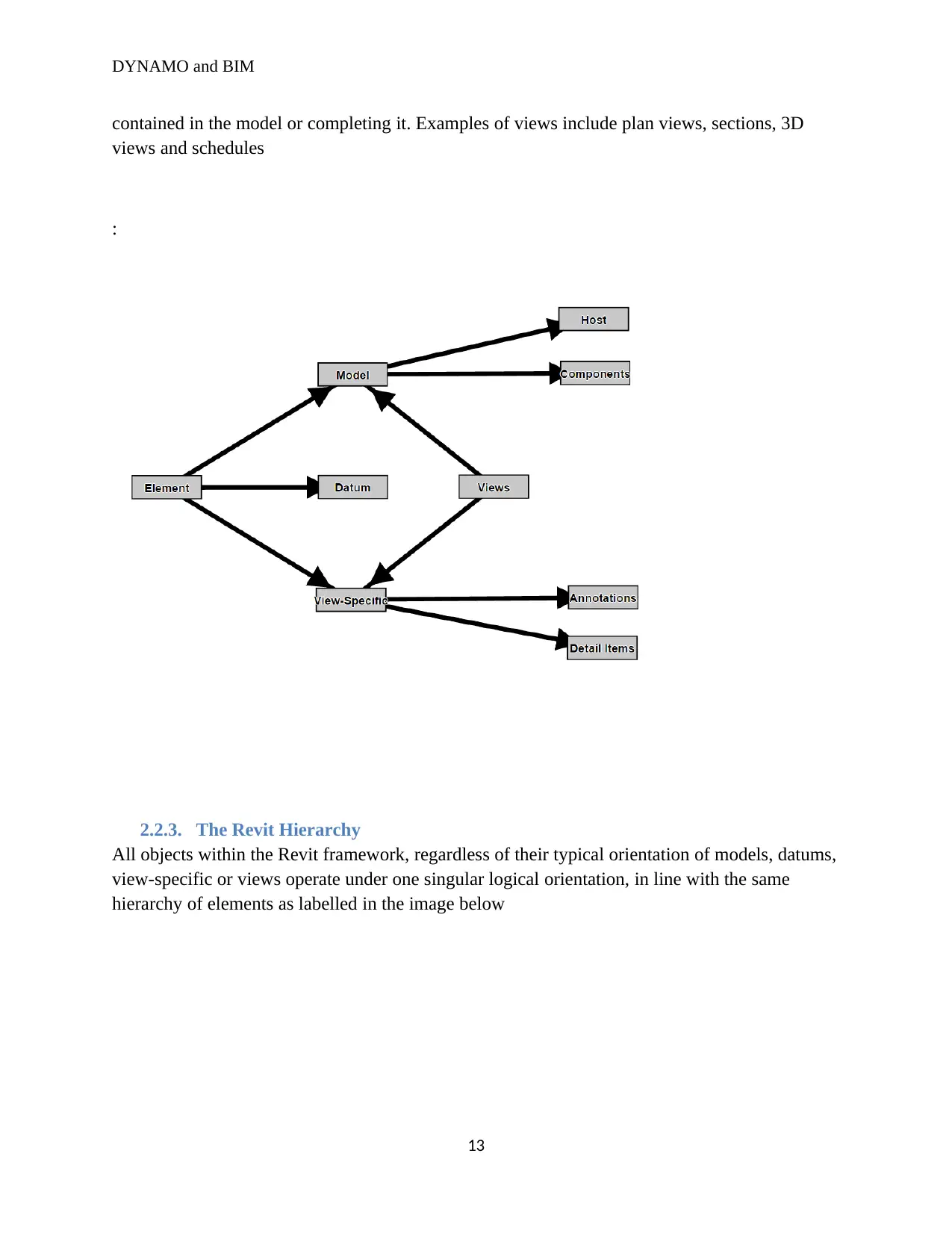
Model elements epitomize the authentic 3D geometry of the building and display in relevant
outlooks of the model. Generally speaking, there three known types of model elements namely:
11
DYNAMO and BIM
i. Hosts
Hosts are largely assembled at the construction location. They are system families in Revit and
are referred to as “Host” elements mainly because they habitually host other design elements.
Examples of hosts include:
Walls and ceilings
Structural walls and roofs
ii. Model components
Model components refer to all the other types of elements found within the building design. They
include windows, doors, cabinets, beams, braces, and mechanical columns.
iii. Datums
Datums are the key references found within the model, particularly the “Levels”, as a result of
the fact that a major chunk of the elemental composition of the models are attached or referred to
the aforementioned levels. Datums are exceptional mainly due to the fact that even though they
are presented in outlook as 2D elements, and are not displayed in 3D views, they are in fact
three-dimensional elements. Their purpose is to aid in defining the context of the project as in,
coming up with grids, levels and reference planes.
2. View-specific elements
View-Specific elements exhibit only in the views in which they are positioned and their role is
to aid in describing or documenting the model. Essentially, there are 2 types of view-specific
elements namely:
i. Annotation elements
Annotation elements refer to sets of 2D components whose role is to document the model and
maintain the model’s scale on paper. Annotation elements include dimensions, tags and keynotes
among others.
ii. Details
Details are two dimensional bits and pieces that provide in-depth specifics about the building
model in a particular view. Details are model-scaled and they include detail lines, filled regions
and other 2D detail components.
3. Views
Views are components that give room for the ultimate access and subsequent documentation of
all the raw data that are contained within the model. Views play the role of connecting model
objects and view-specific objects. Let´s consider a situation where Model objects purely exist
within the model but on the other hand view specific objects exist solitarily in the views within
which in which they are positioned, the role of the views will be to show the information
12
DYNAMO and BIM
contained in the model or completing it. Examples of views include plan views, sections, 3D
views and schedules
:
2.2.3. The Revit Hierarchy
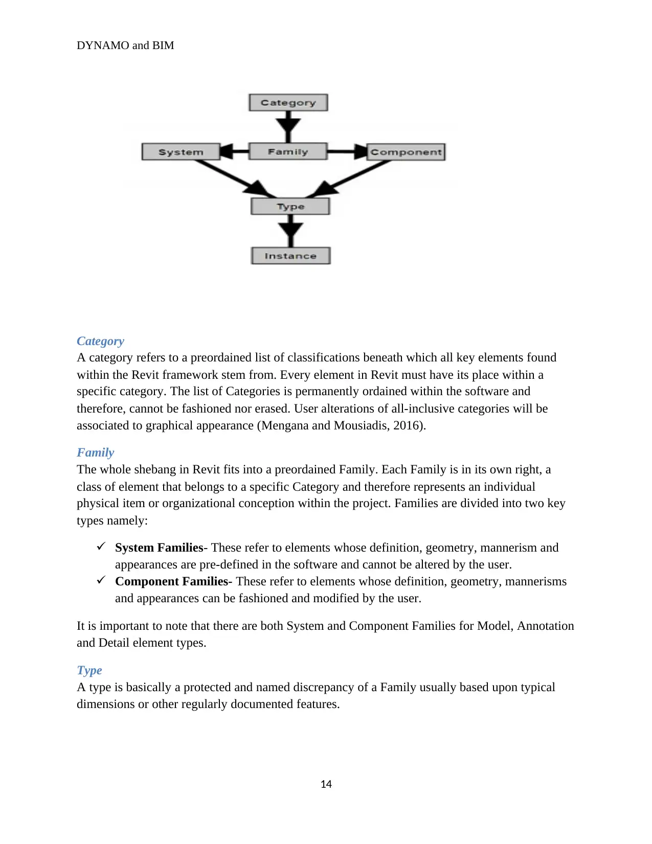
All objects within the Revit framework, regardless of their typical orientation of models, datums,
view-specific or views operate under one singular logical orientation, in line with the same
hierarchy of elements as labelled in the image below
13
Paraphrase This Document
Need a fresh take? Get an instant paraphrase of this document with our AI Paraphraser
DYNAMO and BIM
Category
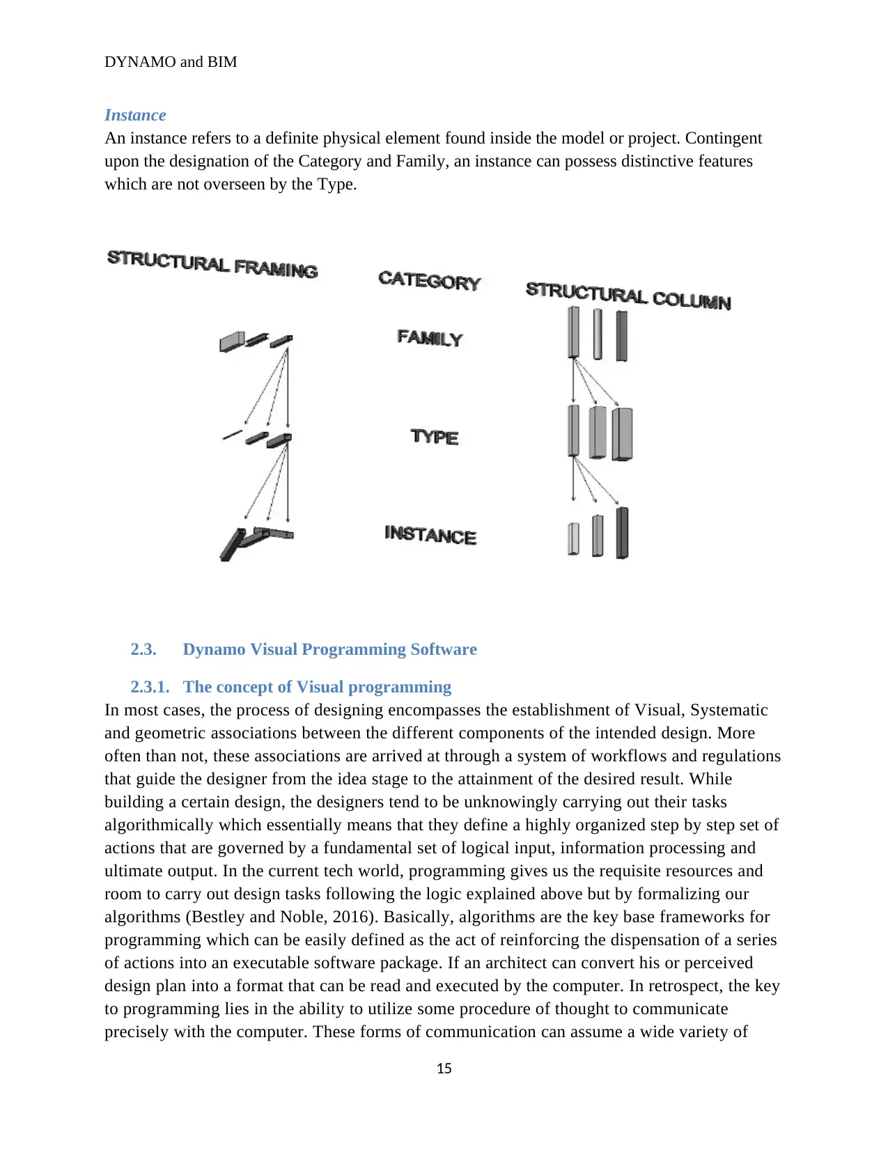
A category refers to a preordained list of classifications beneath which all key elements found
within the Revit framework stem from. Every element in Revit must have its place within a
specific category. The list of Categories is permanently ordained within the software and
therefore, cannot be fashioned nor erased. User alterations of all-inclusive categories will be
associated to graphical appearance (Mengana and Mousiadis, 2016).
Family
The whole shebang in Revit fits into a preordained Family. Each Family is in its own right, a
class of element that belongs to a specific Category and therefore represents an individual
physical item or organizational conception within the project. Families are divided into two key
types namely:
System Families- These refer to elements whose definition, geometry, mannerism and
appearances are pre-defined in the software and cannot be altered by the user.
Component Families- These refer to elements whose definition, geometry, mannerisms
and appearances can be fashioned and modified by the user.
It is important to note that there are both System and Component Families for Model, Annotation
and Detail element types.
Type
A type is basically a protected and named discrepancy of a Family usually based upon typical
dimensions or other regularly documented features.
14
DYNAMO and BIM
Instance
An instance refers to a definite physical element found inside the model or project. Contingent
upon the designation of the Category and Family, an instance can possess distinctive features
which are not overseen by the Type.
2.3. Dynamo Visual Programming Software
2.3.1. The concept of Visual programming
In most cases, the process of designing encompasses the establishment of Visual, Systematic
and geometric associations between the different components of the intended design. More
often than not, these associations are arrived at through a system of workflows and regulations
that guide the designer from the idea stage to the attainment of the desired result. While
building a certain design, the designers tend to be unknowingly carrying out their tasks
algorithmically which essentially means that they define a highly organized step by step set of
actions that are governed by a fundamental set of logical input, information processing and
ultimate output. In the current tech world, programming gives us the requisite resources and
room to carry out design tasks following the logic explained above but by formalizing our
algorithms (Bestley and Noble, 2016). Basically, algorithms are the key base frameworks for
programming which can be easily defined as the act of reinforcing the dispensation of a series
of actions into an executable software package. If an architect can convert his or perceived
design plan into a format that can be read and executed by the computer. In retrospect, the key
to programming lies in the ability to utilize some procedure of thought to communicate
precisely with the computer. These forms of communication can assume a wide variety of
15
DYNAMO and BIM
computer languages ranging from Java Script, Python or C programming. If one is in a
position to come up with repetitive collection of commands then the next logical step would
be to translate it for the computer. Once these commands are translated to the computer, it
will be able to carry out whatever task that is asked of it through the aforementioned
commands. In summary, one would say that the power of programming lies in the fact that it
enables the computer to execute different sets of tasks that are assigned to it, numerous times
without the possibility of delay or mundane errors (Minsky and Papert, 2017).
The concept of Visual Programming is quite similar to programming which has been
explained above mainly because the path to the desired outcome is principally the same for
both programming and visual programming, as in they share the same background of
formalization. However, when dealing with Visual Programming the requisite set of
commands and associations of the program are defined via a Visual or graphical user
interface. Basically, this is done by linking pre-packaged nodes together rather than typing a
series of text bound by syntax (Felleisen and Krishnamurthi, 2018). In a way, the Visual
aspect of programming diminishes the barriers to full access to Revit and creates a means
through which designers can communicate with the main BIM software. Currently, there are
numerous visual programming software packages that fit into this category but Dynamo
Visual Programming software is by far the most useful software within this category.
2.3.2. Dynamo Visual Programming Software
Dynamo Visual Programming Software is a tech-based package that functions alongside Revit
and performs the role of extending the capabilities and power of Revit. Dynamo Visual
Programming Software carries out its intended purpose by providing the much needed access to
the Revit Application Programming Interface (API) in an easier and handier method. It is also
important to note that while using Dynamo Visual Programming Software the user does not have
to type in sophisticated programming codes but instead he or she can come up with meaningful
programs by influencing the built-in graphic elements which are also referred to as nodes. It is
important to note that Dynamo was not originally developed with the aim of being used in BIM
but instead it bears an enormous historical value as a key simulation language accompanied with
graphic-based representations which were formed inside the realm of cutting-edge system
crescendos and analytical backdrops (Yan, 2017). Dynamo was originally developed with an aim
of being used for industrial dynamics but as time went by, it evolved and was introduced into
various sectors to be applied in a wide variety of aspects including but not limited to urban
design, population and asset studies and most recently, Building and Information Modelling
(BIM).
The journey of Dynamo Visual Programming software began in 1958 when unknowingly, a
programmer known as Richard Bennett who at the time was a staff member of MIT was asked
by Jay Wright Forester to calculate the requisite solutions to a set of equations for a Harvard
Business Review paper which was concerned with the topic of Industrial Dynamics. In his own
volition, Richard Bennett implemented a system referred to as “Simulation of Industrial
16
Secure Best Marks with AI Grader
Need help grading? Try our AI Grader for instant feedback on your assignments.

DYNAMO and BIM
Management Problems with lots of equations” (SIMPLE). SIMPLE served as a proof of the
applicability behind the theory of Dynamo Visual programming software because it was able to
perceive coded equations as symbolic inputs and thereby calculate their answers. Dynamo was
initially designed under the stewardship of Jay Wright Forrester, Phyllis Fox, and Alexander
among others with the following goals:
To facilitate the easing of usage of programming concepts by the industrial dynamics
design community which was not necessarily made up of experienced programmers.
To facilitate the instantaneous implementation of the assembled design without having to
under the tedious job of generating a transitional item file.
To facilitate the generation of graphical Outputs while making use of line printers and
Pen plotter visuals.
At the moment, Autodesk owns the ownership rights of Dynamo Visual Programming Software
and it is important to note that since its innovation, the software has been upgraded several times
so much that it currently boasts of the capabilities to come up with a wide variety of design
forms that would be nearly impossible to create while solely using Revit. In its current format,
dynamo can be used for a wide variety of applications mainly because Dynamo’s base
programming is made up of nodes and an ordinary coding technique. Essentially speaking, the
aforementioned nodes can be interlinked together with a goal of coming up with a set of scripts
that have the ability to influence and control various objects in Revit. Dynamo is linked to Revit
in a manner that if a user were to alter some elements in Revit the same elements will change in
Dynamo too and vice versa. All the elements that exist in Revit can be read directly and made
use of by Dynamo (Zaker and Coloma, 2018). Each node in Dynamo possesses its own function
and a distinct programming code within it. In most cases, nodes occur inform of figures, inputs
and string coordinates among others. Furthermore, the output of each and every node can be
linked to numerous sets of inputs and likewise, each and every input can be linked to numerous
sets of outputs contingent to the nodes in question. In rare cases some nodes only possess a
single input or output that can be linked. In summary, it is important to note that the specifics
within which Dynamo Visual Programming software operates are very extensive and
complicated hence the reason why Autodesk has put in place a web based Dynamo homepage
which contains a very vital user forum where questions associated with the usage of Dynamo can
be answered by other experienced Dynamo users and a common pool of ideas can be formed
with programming professionals and Dynamo experts.
2.3.3. The value of Dynamo Visual Programming Software in Revit
Currently, there several software packages that could be used alongside Revit in place of
Dynamo Visual Programing Software. Users can be able to extrapolate load paths using a wide
variety of calculating software packages such as Robot Structural analysis. Furthermore, there
are lots of software packages that can be used to calculate thermal diffusion losses. Putting the
aforementioned facts into consideration, it is hard to fathom why Dynamo Visual Programming
Software is held in such high regards when it comes to its applications in Building Information
17
DYNAMO and BIM
Modelling (BIM) especially its associations with Revit (Wetzel and Thabet, 2018). The main
question that comes to mind is why is Dynamo Visual Programming Software so unique? Well,
as was previously revealed Dynamo Visual Programming enables the user to alter certain
outcomes by applying certain variations to specific equations in order to attain a wide array of
results for each component. However, this is not the only reason why Dynamo is very valuable
to Revit and BIM in general. There are several other reasons behind the praise of Dynamo Visual
Programming software some of which are outlined below.
i. Automation and Replications
When solely using Revit, in most cases the user will have to manually carry out numerous tasks
repeatedly therefore, making the whole process tedious and time consuming but when Revit is
used in combination with Dynamo Visual Programming Software, the user can repeat several
tasks as quickly as possible.
ii. Acquisition of the requisite access to Revit’s Data organization
Just like other similar software packages, Revit can be influenced using programming
techniques. Despite the fact that Dynamo is unlike the typical instruments of programming, it has
the ability to access Revit’s organizational Data and alter or acquire specific sets of information
within Revit. Dynamo Visual Programming software is designed in a manner that it can be able
to make use of code block nodes and Python nodes to write codes that are analogous to scripted
programming software packages.
iii. Amalgamation with other software
Dynamo Visual Programming software can easily be interlinked with other software packages
via nodes whose purposes are to create room for the user to minimize time wastages while using
Revit. For example, the outputs obtained from Dynamo Visual Programming software can be
stored in an excel spread shit file.
iv. Being able to test a wide variety of tasks in the shortest time possible
This feature goes back to the feature of automation and recurrence. The fact that Dynamo Visual
Programming software is able to undertake a variety of tasks at a quicker rate gives the user
room for making mistakes since he or she will be able to redo the tasks and optimize them within
the shortest time possible while using Dynamo.
2.4. Object-oriented Programming
As has been revealed by previous literature, Revit uses a wide variety of objects which contain
varying characteristics. This ability to use different objects is referred to as object-oriented
programming. Basically, there are four known doctrines of object-oriented programming known
as abstraction, polymorphism, encapsulation and inheritance. Before taking an in-depth look into
these doctrines it is important to understand that even though it is quite difficult to manipulate
the objects while using Revit alone, the emergence of Dynamo Visual Programming Software as
eased the process of accessing Revit’s elements and manipulating their constraints (Cruz, 2018).
18
DYNAMO and BIM
i. Abstraction
Abstraction refers to the process through which sophisticated scripts and codes are abridged. For
instance, while using Revit, despite the fact that it is quite easy for the designer to change the
elevation of a certain wall the programming script that is needed to make these alterations is very
sophisticated. However, while using Revit in connection with Dynamo Visual Programming
software the designer does not have to worry about the challenge of the programming script
because the ability to simplify the sophisticated scripts the designer can see the easier path
towards changing the wall’s elevation.
ii. Polymorphism
Polymorphism is a term which derives its roots from a Greek word which means “many shapes”.
This doctrine provides a means through which a user can make use of the Revit Families, as in, if
the user interacts with a wide variety of objects which share a similar means of acquiring the
requisite access to their features, the user will be able to use the same means of access for all the
objects.
iii. Encapsulation
When using Revit to create Models, the user has to incorporate a wide variety of objects ranging
from stockades, floorings and rooftops among others. When all these objects are linked together
they tend to communicate with each other, however, each of the aforementioned objects
surreptitiously maintains its form within its Revit family and therefore, other objects do not have
straight contact to its form. This basically means that, despite the fact that an object’s form can
vary according to the different techniques used by the designer, the features of any particular
object can only be changed from within, as in, if the designer intends to alter certain properties of
a wall, he or she as to make the desired changes from the wall itself and not from any other
object such as the floor.
iv. Inheritance
Anyone who has ever had the chance to use Revit will notice that objects contained in Revit
share identical traits. These traits often include but are not limited to elevation, surface area and
length. Since the objects have identical attributes, the user is able to utilize the same key script
for all of them albeit with some minor changes to different objects. Basically, as was formerly
outlined, a hierarchy can be created from various aspects such as categories, types, instances and
families. The initial script that is used by the user can be reused while dealing with all the other
subsequent objects. It is also important to understand that the highest class within the hierarchy is
the parent class and logically, the lowest class is the children class which falls beneath the parent
class.
2.5. Application Project Interface (API)
During the commencement of any particular project, Revit automatically fashions a database for
that project. Unless one is a tech wizard, it is nearly impossible to acquire the requisite access to
the Revit database without making use of a programming apparatus. However, there is no need
19
Paraphrase This Document
Need a fresh take? Get an instant paraphrase of this document with our AI Paraphraser
DYNAMO and BIM
for worry because since the development and application of Dynamo Visual Programming
software Revit users can now easily gain access to the Revit database using the Application
Program Interface (API). Application Programming Interfaces (API) refers to a set of
components which occur beneath all the applications and software packages and their role is to
share the available pieces of raw data amongst each other (Thorsen, 2016). In the current tech
universe, it is a universally known fact that all sorts of processor-based programs that are
interlinked together, for example, Revit and Dynamo make use of Application Program
Interfaces (API).
Chapter 3
Methodology
Chapter overview
This chapter and its subsequent sub topics aim at explaining the research experimental course in
achieving the research objectives. To bring out the full idea of the experiment progression with
the building information modeling (BIM), the chapter is divided into major sub sections each
detailing critically its components and describing fully the methodology while outlining the
model geometry. The chapter also seeks to show how the dynamo can be implemented in the
Revit model.
Building information modeling notion
Brief history of BIM
As cited earlier in this thesis, BIM is user interactive software that enables the constructors to
share and exchange building ideas which includes the how the entire building process will take
place. It is a celebrated algorithm which has restructured the building industry, special thanks to
Professor Charles M. Eastman, from the Georgia Institute of Technology who invented this
building idea around the year 1970 (Smith, 2014). It took only about a decade before Professor
Charles was upgraded to give the world the first the BIM functional model. Over time the idea
has been improved with more technology been added to it. Today engineers can use BIM to have
a technical overview of the building course, use it to plan, design, construct a building and even
gobble a building; the idea has completely shifted from being scholar-based to technical based.
The use of BIM is round the globe is evenly spread, with construction present in the USA, Great
UK, China, Hong Kong, Dubai, South Africa and in Australia. Some governments for instance
the American and British government have moved steps ahead by setting the use of BIM in new
20
DYNAMO and BIM
major construction as a compulsory regulation. Its three dimension replica generation is doing
the magic (Johnson, 2015).
BIM dimension
Building or rather setting up a constructional site is not an event but a continuous process which
is developed by setting up of extreme dimensions and stages of construction. As the building
grows its takes different LOD values mostly from 100 to 200 and far beyond it (Solihin and
Eastman, 2015). The same concept applies to the BIM modeling functions. It is imperative to
note that BIM models consists of 5 dimensions; 3D, 4D, 5D, 6D and 7D, all these dimensions
plays different roles at different levels of the construction phase. The 3D dimension also named
the 3rd dimension is simple basic components of the building geography which comprises the X,
Y and Z components of the building giving the engineers and the constructors the visualization
of the building, it is advantageous since it allows the engineers to have a look on the structure
visualization thus enabling them to share their ideas on the expectation of the building structure
which will also empower them to solve mistakes that would have been found during the last
stages and construction period of the building (Osello, 2012).
The 4th dimension is based on other building aspects like time and scheduling of events (Zhang
and Venugopal, 2013). The idea to implement the 4th dimension on building models was first
sourced in the late 20th century around 1990 by Sir Retik. It was generated from the idea the 3D
dimensions of a building was not enough since other major aspects also needed to be considered.
It was presumed that adequate planning of available resources will constitute proper planning.
Sir Retik was experimenting on computers ability to produce graphical images which he
succeeded and produced a functional constructional dimension which also formed basis for the
5th building model. It is important that crucial items like time and space available are sorted with
clearly planned time for each stage of construction, suitable sequencing of building proceedings
which be advantageous since it ensures that they exists proper coordination of architects and
constructors, augmentation of safety procedures since construction will be equated. Unlike the
4th dimension the 5th dimension focus on the monetary side of construction (Woo, 2016). It is
budgetary based, an item that makes it one of the most significant building dimension, it allow
the promoters and the owners to have a fiscal visualization and the space to plan on the probable
man power, machinery and the best financially suitable construction constituents. Generally, a
proper fiscal planning is the key in ensuring a smooth construction from the beginning till the
end. The 5D building model was approved due a consideration that up to 62% of new
construction sites, daily constructional operation are hampered due to financial constraints. It
allowed room for instant fiscal estimations against time in which the building constructors will
have the pleasure of gauging their pecuniary muscle before deciding on to kick off the
construction process (Sanguinetti and Eastman, 2012).
The 6th dimension focuses on the energy consumption by the construction; it aims at information
the engineers of the need to use efficient data and energy resources in powering the site, also it
forms the basis of the building adoption to renewable energy after completion, it advantageous
21
DYNAMO and BIM
since it permits quicker decision making considering energy. Lastly the 7th building dimension
emphases on up keep of the building till its start of demolition. It ensures that all the safety
appliances such as the fire extinguishers are on place, proper lighting condition and any other
appliances installed on during the construction phase. It is beneficial since it ensure that the
building remain safe during it usage time and also ensures that the safety mechanism in place
such as emergency exits are fully functionally (Ibrahim and Schipporeit, 2014).
The knowledge and impact of each building dimension that existed before the year 1990 is
totally different with what is presumed of it today. Thanks to ever changing world and a
constantly upgrading technology transferred into building industry. It is possible to gauge today
the level at which BIM beam is used and how it was used previously; with level 0 at the year
1990, level 1 at the year 2000, level 2 at the year 2010 and finally now at gauging level 3 at the
year 2020 (Sanguinetti & Eastman, 2012). As noted above, the levels of BIM usage changes
every 10 years, nobody knows what the future holds for the BIM D’s, but it looks positive with
immeasurable level of certainty.
Visual programming essentials
Human beings like simplified exertion, and for that reason the need to reduce work load by use
of pivots and levels in manually work was greatly emphasized. In programming world, the
visual programming was introduced as a clinical pivot to assist the engineers and constructors
design buildings and other constructional needs. The visual programming is supported by the
visual syntax and semantics that do create the visual images in the work space (Shin & Magnenat
2014).
As mentioned above the visual syntax and semantics in visual programming are designed in a
meek manner which does enable the engineers to construct meaningful constructional objects
without the need of cramming some common programming nodes and syntax. The combination
of parametric scripting with building analytics in visual programming results in creation of high
definition graphic images of building
Visual Programming Language (VPL) is the specified type of programming language which
enables the engineers to design the building images without the writing some specified
programming codes but rather enjoying using the pre-packaged nodes that only need supervised
connection to create wonderful images (Burnett, 2011). This is exclusively advantageous since it
saves time that would have been used for the writing of the textual code and the difficult to
understand the basic programming knowledge before designing items Booth & Stumpf 2013).
Ideally VPL language is designed same for text based programming and visual programming
which makes it an ideal visual tool, though critics argue that the algorithms and simplified nodes
used in the VPL do not meet the minimum requirement for a competitive programming
environment.
22
Secure Best Marks with AI Grader
Need help grading? Try our AI Grader for instant feedback on your assignments.
DYNAMO and BIM
Dynamo
Dynamo is an add-in software for Autodesk Revit and Vasari; mostly used with Autodesk Revit,
which enable engineers and constructors to design graphical images in the workspace with the
use of computational design and automation processes assisted by a functional nodes that are
task specified( Kensek, 2014). By providing users with powerful functions such as mathematical
maneuvers, gradients, listing, scripting, geometry handling, Excel data importation and
exportation, it enables them to perform sophisticated data manipulation, execution of relational
structure, and comprehensive geometric controls by sourcing, reading and writing data from
external sources and editing and manipulating data to fit, functions that are impossible when
using a conventional modeling interface (Seghier & Samuel, 2017). This is because dynamo
enables it’s’ users to control computational scheme workflows inside the setting of a BIM
environs. Through networking of a Revit document with the Revit application and the Dynamo,
images can be manipulated, sorted, read and data fitted to fit the required specification. Revit
nodes are the core functioning elements of Revit Application Programming Interface, thus
gaining the ability to control families by manipulation, creating, deleting, formatting families
within its domain and editing family’s parameters. The .dyn format is used to save dynamo
scripts and projects (Kensek, 2015).
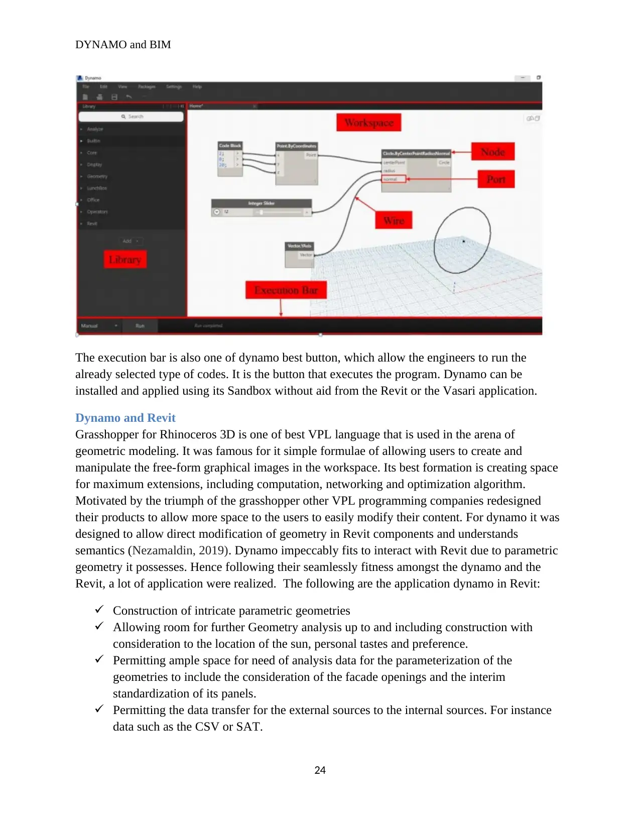
Dynamo user interface
Dynamo user interface is a simple interface which enables engineers to appreciate the visual
programming process. It is simple divided into two major sides the right and the left hand side.
The left sides contains a list of prepared nodes that can be used to execute the desired graphical
representation while the right sides contains the workspace which allows the engineers to
observe what is being designed visual with the aim of making necessary corrections and interim
actions enabled by the graphical code editor (Kensek, 2014). The dynamo workplace is the main
core of the visual programming which encompasses the processes of connecting the nodes with
Wires. Nodes are the objects and spaces which are connected with wire to form the visual
program assisted by nimble rectangular points on Node which acts as the receptors for the wires,
thus encouraging the flow of information from left to right via the ports. Since information is
flowing from the left to right, the input nodes are on the left while the output nodes are on the
right side of the ports.
23
DYNAMO and BIM
The execution bar is also one of dynamo best button, which allow the engineers to run the
already selected type of codes. It is the button that executes the program. Dynamo can be
installed and applied using its Sandbox without aid from the Revit or the Vasari application.
Dynamo and Revit
Grasshopper for Rhinoceros 3D is one of best VPL language that is used in the arena of
geometric modeling. It was famous for it simple formulae of allowing users to create and
manipulate the free-form graphical images in the workspace. Its best formation is creating space
for maximum extensions, including computation, networking and optimization algorithm.
Motivated by the triumph of the grasshopper other VPL programming companies redesigned
their products to allow more space to the users to easily modify their content. For dynamo it was
designed to allow direct modification of geometry in Revit components and understands
semantics (Nezamaldin, 2019). Dynamo impeccably fits to interact with Revit due to parametric
geometry it possesses. Hence following their seamlessly fitness amongst the dynamo and the
Revit, a lot of application were realized. The following are the application dynamo in Revit:
Construction of intricate parametric geometries
Allowing room for further Geometry analysis up to and including construction with
consideration to the location of the sun, personal tastes and preference.
Permitting ample space for need of analysis data for the parameterization of the
geometries to include the consideration of the facade openings and the interim
standardization of its panels.
Permitting the data transfer for the external sources to the internal sources. For instance
data such as the CSV or SAT.
24
DYNAMO and BIM
Authorizing the accessing of the Revit programming interface (API) files which enables
the users to control and manipulate the families and exercise the manipulation of
parameters.
And lastly dynamo in Revit can be applied to allow data mining such as the quantity
takeoffs.
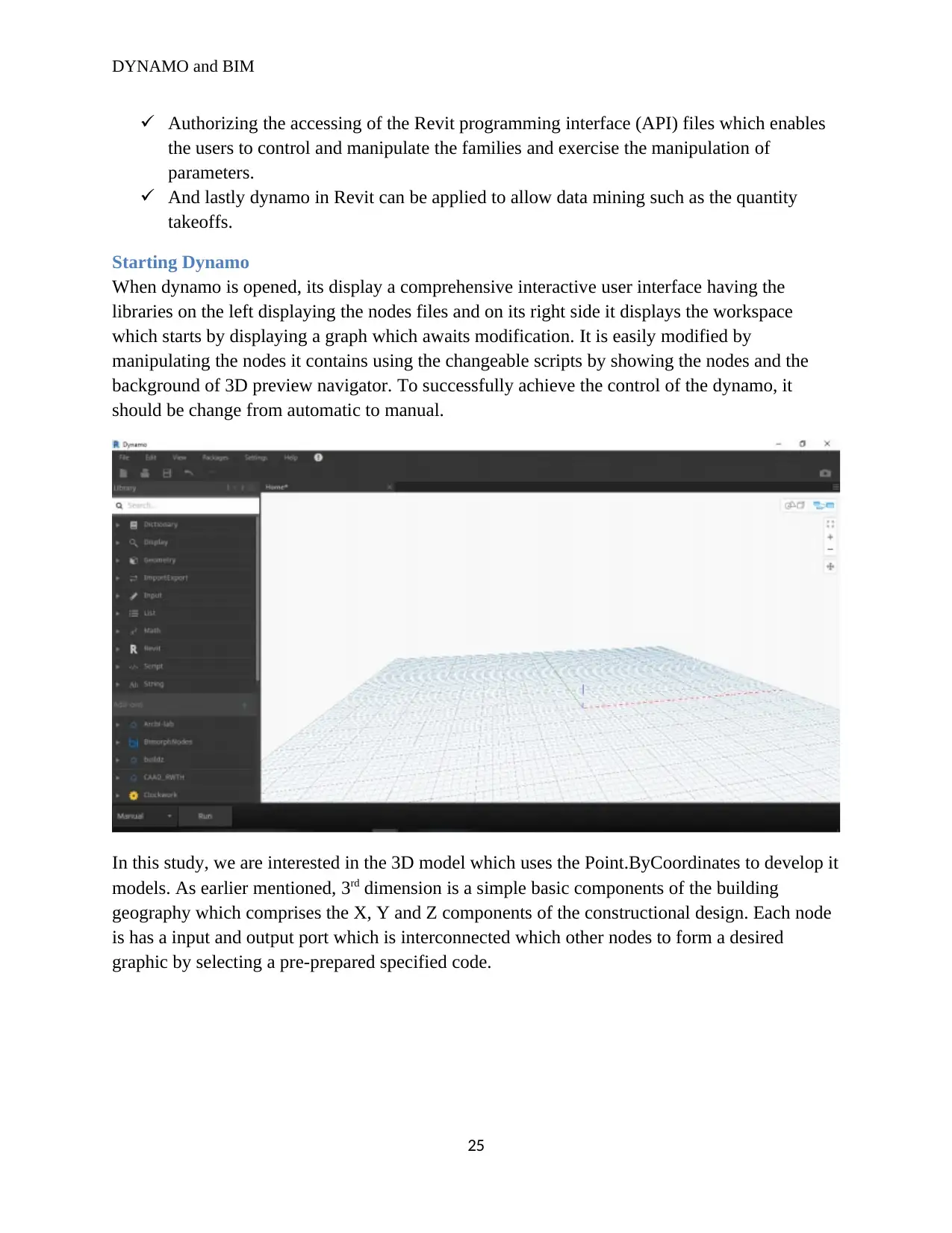
Starting Dynamo
When dynamo is opened, its display a comprehensive interactive user interface having the
libraries on the left displaying the nodes files and on its right side it displays the workspace
which starts by displaying a graph which awaits modification. It is easily modified by
manipulating the nodes it contains using the changeable scripts by showing the nodes and the
background of 3D preview navigator. To successfully achieve the control of the dynamo, it
should be change from automatic to manual.
In this study, we are interested in the 3D model which uses the Point.ByCoordinates to develop it
models. As earlier mentioned, 3rd dimension is a simple basic components of the building
geography which comprises the X, Y and Z components of the constructional design. Each node
is has a input and output port which is interconnected which other nodes to form a desired
graphic by selecting a pre-prepared specified code.
25
Paraphrase This Document
Need a fresh take? Get an instant paraphrase of this document with our AI Paraphraser
DYNAMO and BIM
Experimental methodology
Methods
This study focuses on the use of dynamo in the building and construction industry, to realize the
best results with interaction with dynamo software, it was necessary to install the Revit
application which supports the performance of the dynamo. This is because of the architectural
template which are visible in the dynamo can be easily accessed in the Revit model. Dynamo
script can function both manually and automatic modes, however the challenge with the
automated mode is that it is prone to errors, inaccuracy rendering it inefficient. Due to these
unbearable challenges with the automated mode it was necessary that we use the manually mode
of the dynamo to achieve our desired results. The measurement scale in Revit workspace is
accurate since it is measured in millimeters, therefore necessitating the need to rescale the
measurement in the dynamo to extra-large. The ability of dynamo to contain the homemade
nodes created in the custom node script makes it obligatory to clear all the files and contents
available in the computer from previously installed version of dynamo which could have created
run time errors within the application. To solve this, dynamo was uninstalled then downloaded
and installed again.
Details of the dynamo script
Dynamo is a simple building programming software designed to support people and engineers to
design building and other constructional interests. It is modest that someone with little or no
programming experience can use to design something meaningful (Elsayed, & Squasi, 2017). It
is because of its clearly and smartly designed user interface which has all the elements saved in
distinctive folders. For example, when dealing with specific files say floor, there is a specified
node for that particular task.
Elements placement
It is much easier to place elements using the Revit model due to its accurate measuring abilities.
But due to the experimental objective, the study was limited to using the dynamo workspace. To
realize this objective straightforwardly by place the elements via the dynamo workspace, it was
essential to activate the automatic mode of the dynamo nodes which hence activates the
connection of nodes to each other (Nguyen, 2020). The placement of the building elements are
done following chronological order starting from the floor, wall and finally to the roof. During
this orders each placement element is placed and resettled to fit the requirement placing
specification. This is because each building object requires different specification of varied
elements.
Floors
These are the steps and procedures followed during the installation of the floor in the dynamo
visual programming software:
We start by picking the floor node, under the model element node.
26
DYNAMO and BIM
It is then followed by moderate holding of the anticipated location where the floor lines
will run across.
The node picks the lines and converts them into visible and realistic floor surface using
the CurveElement.Curve node.
Finally the Floor.ByOutlineTypeAndLevel node places the floor.
It also allows one to edit the floor details (Kensek, 2017).
Walls
These are the steps and procedures followed during the installation of the walls in the dynamo
visual programming software:
We start by picking the wall node, under the model element node.
It is then followed by moderate holding of the anticipated location where the wall lines
will run across.
The node picks the lines and converts them into visible and realistic wall surface using
the Element.SetParameterByName node.
Finally the Element.SetParameterByName node and AutoCad lines places the wall.
It also allows one to edit the wall details.
Roofs
These are the steps and procedures followed during the installation of the roofs in the dynamo
visual programming software:
We start by picking the roof node, under the model element node.
It is then followed by moderate holding of the desired location where the roof lines will
run across.
The node picks the lines and converts them into visible and realistic roof surface using
the FootPrintRoof.ByEdgesAndSlopes node.
Finally the FootPrintRoof.ByEdgesAndSlopes places the roof.
It also allows one to edit the roof details.
Windows and doors
To create windows and doors in the dynamo visual programming software we select a host
which horde the doors and windows. It is in simple building plan that the windows and doors are
located alongside the walls of the designated building. Therefore the host will be the walls, it is
possible to create multiple doors and windows having the same specification using
Springs.HostedInstance.ByPoints node while the node Curve.PointsAtEqualChordLength divides
the number of doors and windows present in a wall (Kensek, 2017).
The case study
Using dynamo to program the building is a lot easier and also fun like in nature. Just more like
driving a car you need to understand some basic concept; it’s the engine the powers the car and
the driver control the engine. Same notion applies to the application of dynamo in Revit. The
27
DYNAMO and BIM
engineer using the dynamo does not design the building but do govern the dynamo as it propels
itself to design building using the commanded predesigned codes. So back to our car idea, to
impeccably drive it you need to have a solid background of how the car engine functions, not too
deep like the car mechanic, but good enough to know when to refuel the oil, gas and checking
the if the car types are okay or any other crucial part. Knowing this concept, let’s look at the
advantages of the dynamo in Revit.
Why dynamo and Revit
i. Thinking mutually and comprehensively
Relating with the concept of car, as you drive along with it, you continuously increase
your understanding of it, for instance for a manually powered car, the you will have
problems drive it on higher gears like 3 or 4 in a complicated and rough terrain whereby
you will be forced to use lower gears such as 1 and 2. The same concept applies to using
dynamo to building. Well, through the interaction with desired design, the architects rely
on instinct and creativity to design a building which can be a challenging task. However,
dynamo provide a crucial link for the architects to change the design basing the
technicalities that arrive on due course. Therefore, dynamo and Revit Autodesk
applications present to the engineers the ability to think mutually and comprehensively
inclusively (Denis, 2014).
ii. Enabling the testing of building performance
Everything under developing requires testing to ensure that it has met the minimum
conditions set for it development. Before building even starts its own construction, the
engineers constructing it will have the immaculate opportunity to view it, measure its
correspondence with the building dimension for instance the 3D, 4D up to 7D. By doing
so it enables the engineers to check and test the building, thereby acknowledging if it is
fit for construction or if it requires some small changes before it acknowledged for
construction (Mengana & Mousiadis, 2016).
iii. Ease of exploring building design preferences
The only reason for the creation of Revit and Dynamo was because the need of allowing
the building engineers multiple designing architectures basing on different needs of the
construction wants (Sandzhiev and DA, 2016). Using dynamo computation framework
industrial engineers can formulate over a hundred pieces of designs upon which the
constructors can decide the best option to go for.
Images of different construction designs
28
Secure Best Marks with AI Grader
Need help grading? Try our AI Grader for instant feedback on your assignments.
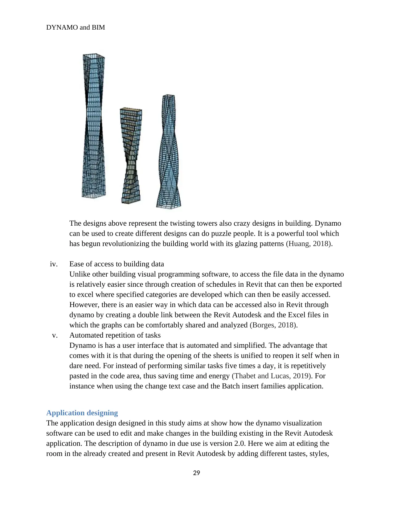
DYNAMO and BIM
The designs above represent the twisting towers also crazy designs in building. Dynamo
can be used to create different designs can do puzzle people. It is a powerful tool which
has begun revolutionizing the building world with its glazing patterns (Huang, 2018).
iv. Ease of access to building data
Unlike other building visual programming software, to access the file data in the dynamo
is relatively easier since through creation of schedules in Revit that can then be exported
to excel where specified categories are developed which can then be easily accessed.
However, there is an easier way in which data can be accessed also in Revit through
dynamo by creating a double link between the Revit Autodesk and the Excel files in
which the graphs can be comfortably shared and analyzed (Borges, 2018).
v. Automated repetition of tasks
Dynamo is has a user interface that is automated and simplified. The advantage that
comes with it is that during the opening of the sheets is unified to reopen it self when in
dare need. For instead of performing similar tasks five times a day, it is repetitively
pasted in the code area, thus saving time and energy (Thabet and Lucas, 2019). For
instance when using the change text case and the Batch insert families application.
Application designing
The application design designed in this study aims at show how the dynamo visualization
software can be used to edit and make changes in the building existing in the Revit Autodesk
application. The description of dynamo in due use is version 2.0. Here we aim at editing the
room in the already created and present in Revit Autodesk by adding different tastes, styles,
29
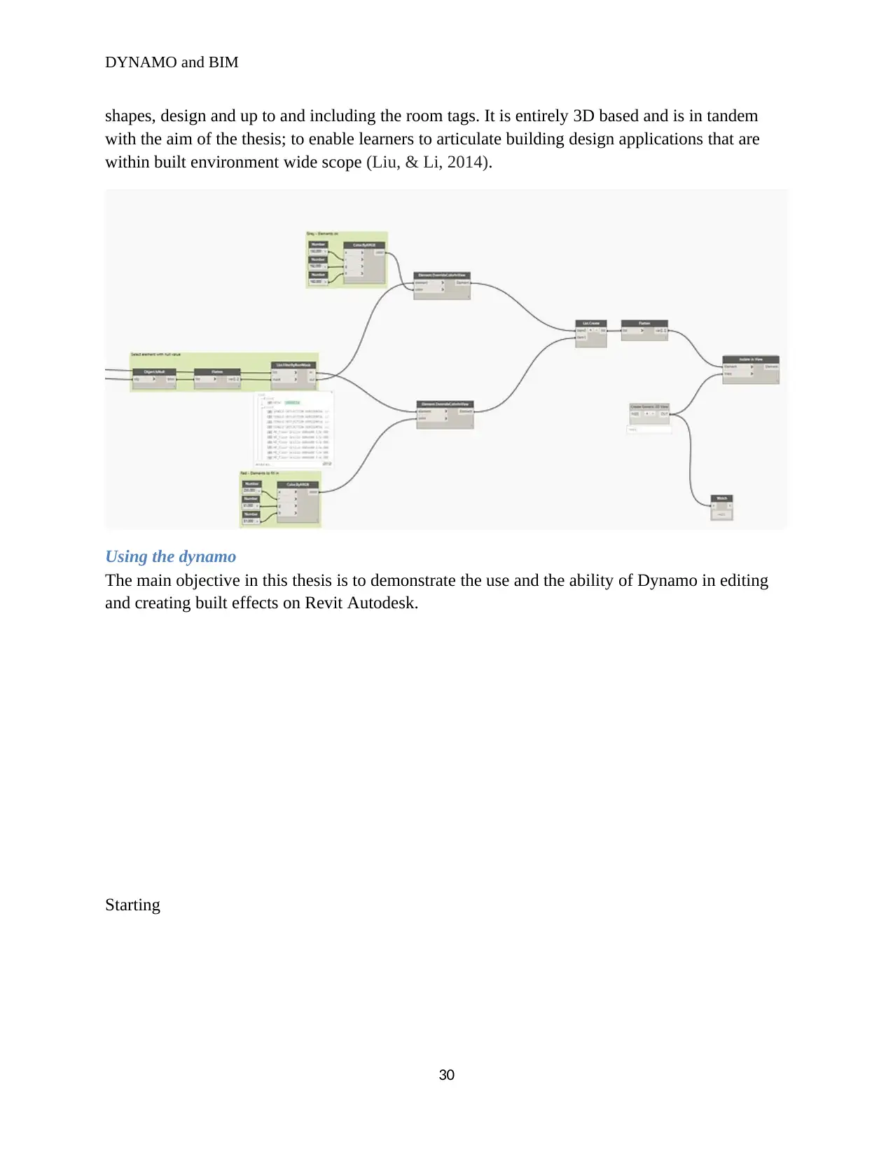
DYNAMO and BIM
shapes, design and up to and including the room tags. It is entirely 3D based and is in tandem
with the aim of the thesis; to enable learners to articulate building design applications that are
within built environment wide scope (Liu, & Li, 2014).
Using the dynamo
The main objective in this thesis is to demonstrate the use and the ability of Dynamo in editing
and creating built effects on Revit Autodesk.
Starting
30
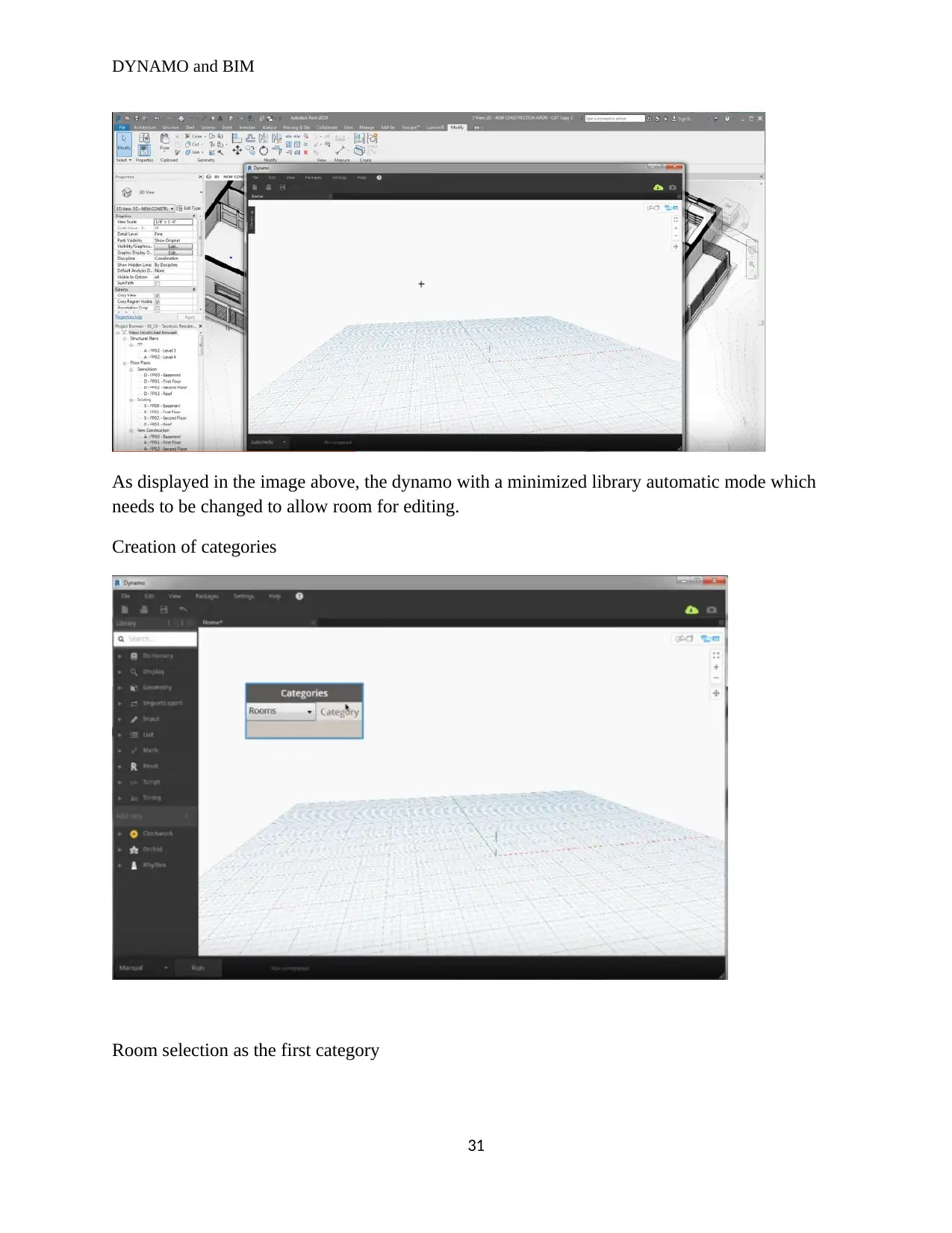
DYNAMO and BIM
As displayed in the image above, the dynamo with a minimized library automatic mode which
needs to be changed to allow room for editing.
Creation of categories
Room selection as the first category
31
As displayed in the image above, the dynamo with a minimized library automatic mode which
needs to be changed to allow room for editing.
Creation of categories
Room selection as the first category
31
Paraphrase This Document
Need a fresh take? Get an instant paraphrase of this document with our AI Paraphraser
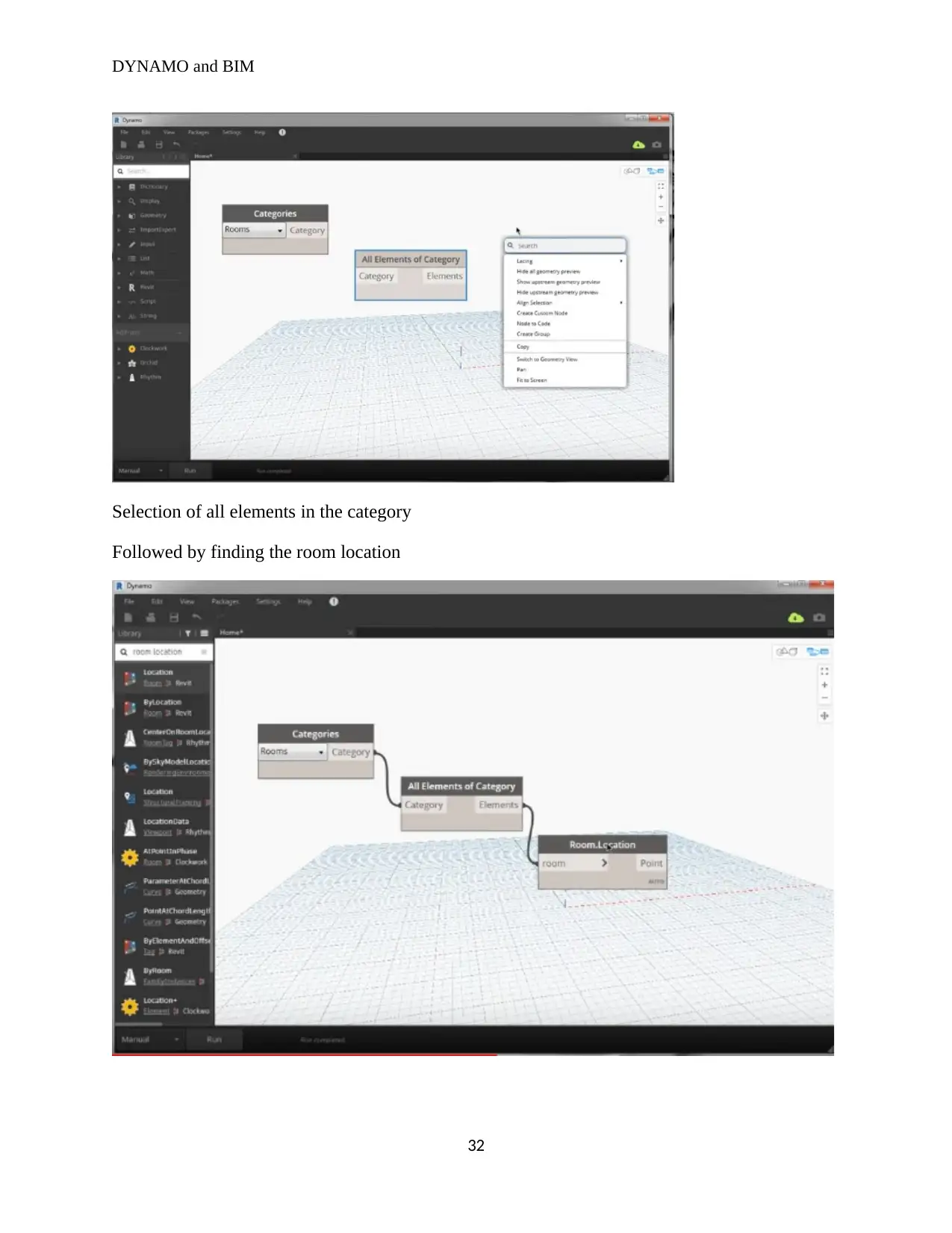
DYNAMO and BIM
Selection of all elements in the category
Followed by finding the room location
32
Selection of all elements in the category
Followed by finding the room location
32
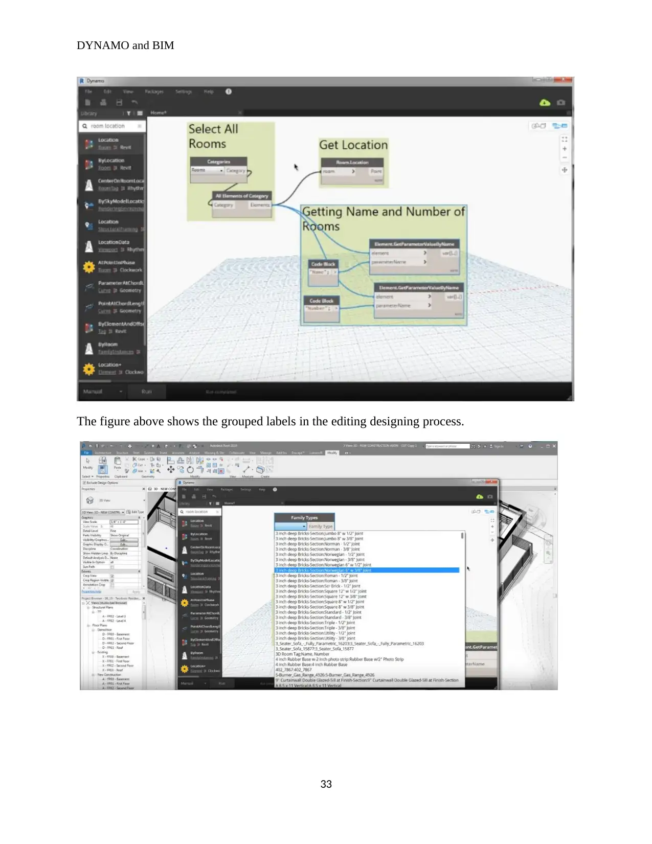
DYNAMO and BIM
The figure above shows the grouped labels in the editing designing process.
33
The figure above shows the grouped labels in the editing designing process.
33
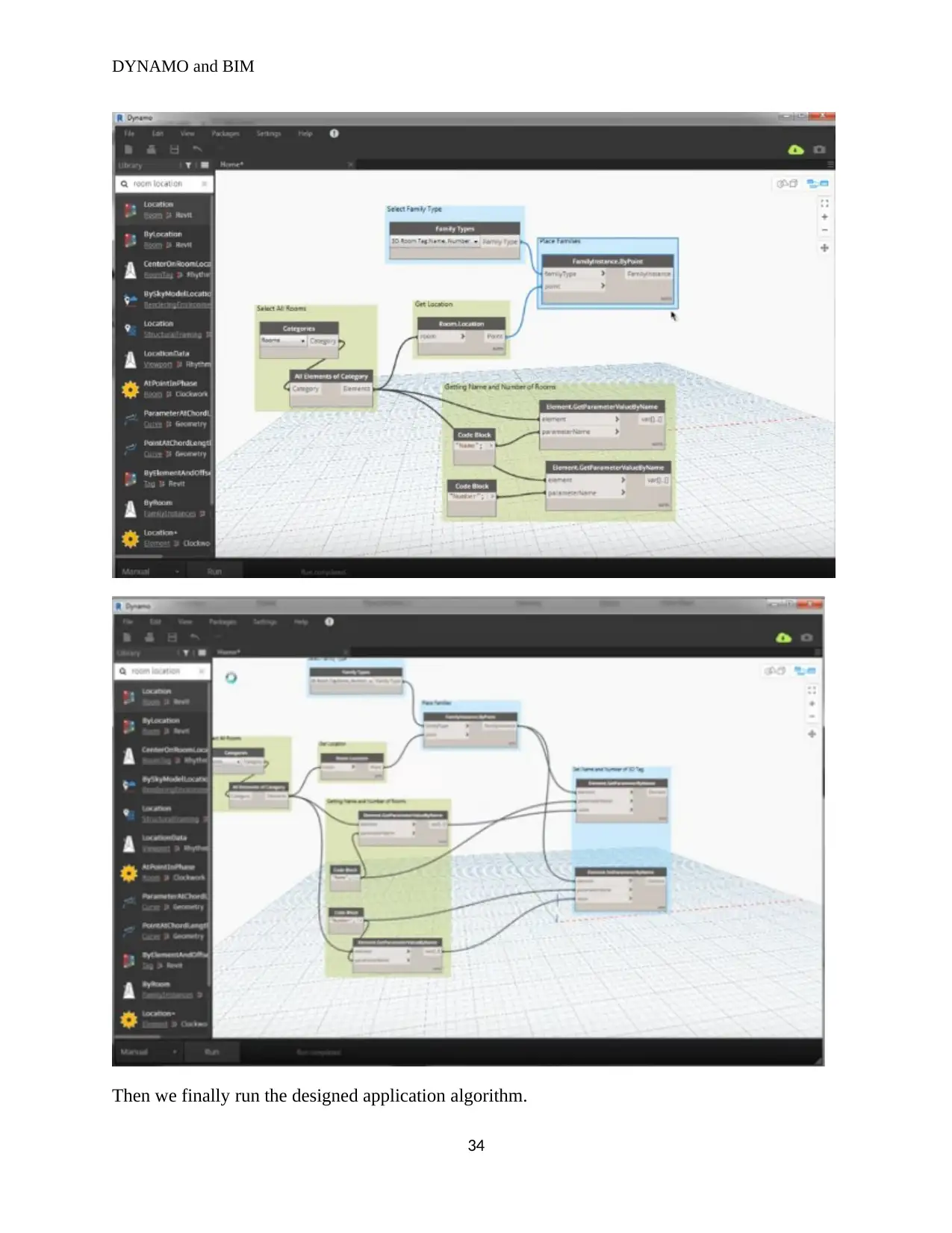
DYNAMO and BIM
Then we finally run the designed application algorithm.
34
Then we finally run the designed application algorithm.
34
Secure Best Marks with AI Grader
Need help grading? Try our AI Grader for instant feedback on your assignments.
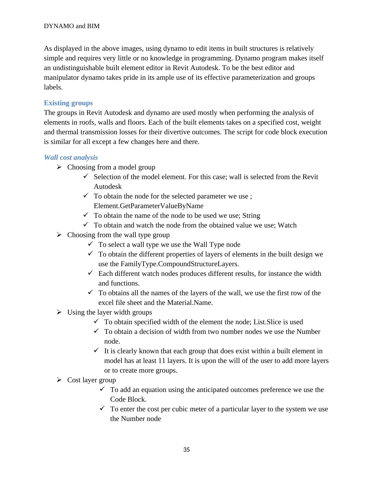
DYNAMO and BIM
As displayed in the above images, using dynamo to edit items in built structures is relatively
simple and requires very little or no knowledge in programming. Dynamo program makes itself
an undistinguishable built element editor in Revit Autodesk. To be the best editor and
manipulator dynamo takes pride in its ample use of its effective parameterization and groups
labels.
Existing groups
The groups in Revit Autodesk and dynamo are used mostly when performing the analysis of
elements in roofs, walls and floors. Each of the built elements takes on a specified cost, weight
and thermal transmission losses for their divertive outcomes. The script for code block execution
is similar for all except a few changes here and there.
Wall cost analysis
Choosing from a model group
Selection of the model element. For this case; wall is selected from the Revit
Autodesk
To obtain the node for the selected parameter we use ;
Element.GetParameterValueByName
To obtain the name of the node to be used we use; String
To obtain and watch the node from the obtained value we use; Watch
Choosing from the wall type group
To select a wall type we use the Wall Type node
To obtain the different properties of layers of elements in the built design we
use the FamilyType.CompoundStructureLayers.
Each different watch nodes produces different results, for instance the width
and functions.
To obtains all the names of the layers of the wall, we use the first row of the
excel file sheet and the Material.Name.
Using the layer width groups
To obtain specified width of the element the node; List.Slice is used
To obtain a decision of width from two number nodes we use the Number
node.
It is clearly known that each group that does exist within a built element in
model has at least 11 layers. It is upon the will of the user to add more layers
or to create more groups.
Cost layer group
To add an equation using the anticipated outcomes preference we use the
Code Block.
To enter the cost per cubic meter of a particular layer to the system we use
the Number node
35
DYNAMO and BIM
To calculate the equation for the code block node we do use the Math.Sum
node
To display the cost of the wall conditioned by its area and cost per cubic
meters we use the Watch node.
Excel group
The main purpose for an excel group is to create data and transfer it into the
excel file created.
To create list of the excel files we need to use the List Create node to create
three different list for the excel file each taking a specified role for the cost
estimation services.
To switch the roles and the columns of the list created we use the
List.Transpose node.
To choose a specified file in the program we use File Path node.
To select the excel file to begin either row or column we use the Number
node
To write of edit the name of the wall we use the String node in the excel
group
To change the selected excel file from the input folders we apply the
Data.ExportExcel
Excel text group
The excel files requires the excel text group which does describes the
outcomes numbers.
Using the excel text group only two nodes are used effectively, the List
Create and the String nodes which perform listing of texts and naming of
texts respectively.
Total wall cost group
To obtain the total cost of wall layers cost we use the Code block
node
To calculate the equation of the code block node we apply the
Math.Sum node.
To demonstrate the cost of the entire wall cost we apply the Watch
node.
Floor cost analysis
Choosing from a model group
Selection of the model element. For this case; Floor is selected from the Revit
Autodesk
To obtain the node for the selected parameter we use ;
Element.GetParameterValueByName
36
DYNAMO and BIM
To obtain the name of the node to be used we use; String
To obtain and watch the node from the obtained value we use; Watch
Choosing from the Floor type group
To select a Floor type we use the Floor Type node
To obtain the different properties of layers of elements in the built design we
use the FamilyType.CompoundStructureLayers.
Each different watch nodes produces different results, for instance the width
and functions.
To obtains all the names of the layers of the Floor, we use the first row of the
excel file sheet and the Material.Name.
Using the layer width groups
To obtain specified width of the element the node; List.Slice is used
To obtain a decision of width from two number nodes we use the Number
node.
It is clearly known that each group that does exist within a built element in
model has at least 11 layers. It is upon the will of the user to add more layers
or to create more groups.
Cost layer group
To add an equation using the anticipated outcomes preference we use the
Code Block.
To enter the cost per cubic meter of a particular layer to the system we use
the Number node
To calculate the equation for the code block node we do use the Math.Sum
node
To display the cost of the Floor conditioned by its area and cost per cubic
meters we use the Watch node.
Excel group
To create list of the excel files we need to use the List Create node to create
three different list for the excel file each taking a specified role for the cost
estimation services.
To swap the roles and the columns of the list created we use the
List.Transpose node.
To choose a specified file in the program we use File Path node.
To select the excel file to begin either row or column we use the Number
node
To write of edit the name of the Floor we use the String node in the excel
group
37
Paraphrase This Document
Need a fresh take? Get an instant paraphrase of this document with our AI Paraphraser
DYNAMO and BIM
To change the selected excel file from the input folders we apply the
Data.ExportExcel
Excel text group
The excel files requires the excel text group which does describes the
outcomes numbers.
Using the excel text group only two nodes are used effectively, the List
Create and the String nodes which perform listing of texts and naming of
texts respectively.
Total Floor cost group
To obtain the total cost of Floor layers cost we use the Code block
node
To calculate the equation of the code block node we use the Math.Sum
node.
To display the cost of the entire Floor we use the Watch node.
Roof cost analysis
Choosing from a model group
Selection of the model element. For this case; Roof is selected from the Revit
Autodesk
To obtain the node for the selected parameter we use ;
Element.GetParameterValueByName
To obtain the name of the node to be used we use; String
To obtain and watch the node from the obtained value we use; Watch
Choosing from the Roof type group
To select a Roof type we use the Roof Type node
To obtain the different properties of layers of elements in the built design we
use the FamilyType.CompoundStructureLayers.
Each different watch nodes produces different results, for instance the width
and functions.
To obtains all the names of the layers of the Roof, we use the first row of the
excel file sheet and the Material.Name.
Using the layer width groups
To obtain specified width of the element the node; List.Slice is used
To obtain a decision of width from two number nodes we use the Number
node.
It is clearly known that each group that does exist within a built element in
model has at least 11 layers. It is upon the will of the user to add more layers
or to create more groups.
Cost layer group
38
DYNAMO and BIM
To add an equation using the anticipated outcomes preference we use the
Code Block.
To enter the cost per cubic meter of a particular layer to the system we use
the Number node
To calculate the equation for the code block node we do use the Math.Sum
node
To display the cost of the Roof conditioned by its area and cost per cubic
meters we use the Watch node.
Excel group
To create list of the excel files we need to use the List Create node to create
three different list for the excel file each taking a specified role for the cost
estimation services.
To swap the roles and the columns of the list created we use the
List.Transpose node.
To choose a specified file in the program we use File Path node.
To select the excel file to begin either row or column we use the Number
node
To write of edit the name of the Roof we use the String node in the excel
group
To change the selected excel file from the input folders we apply the
Data.ExportExcel
Excel text group
The excel files requires the excel text group which does describes the
outcomes numbers.
Using the excel text group only two nodes are used effectively, the List
Create and the String nodes which perform listing of texts and naming of
texts respectively.
Total Roof cost group
To acquire the total cost of Roof layers cost we apply the Code block
node
To calculate the equation of the code block node we apply the
Math.Sum node.
To exhibit the cost of the entire Roof cost we apply the Watch node.
The cost analysis is an important aspect in the building industry as it in tandem with the fifth
building dimension, which requires that financial planning of new construction should be
obligated to inclusion. As earlier mentioned, 62% of new construction structures have their
building activities hindered due to some financial constrains that can up to 87% can be
39
DYNAMO and BIM
eliminated by conducting effective and comprehensive cost analysis on built elements (Ahn &
Yang, 2011).
Only 87% of building financial planning can be effective, the remaining of percentage of the
building fail because of other financial factors and constrains such as the inflation and currency
based glitches.
Summary of the chapter
The third chapter and its subsequent sub topics aimed at explaining the research experimental
course in achieving the research objectives. Beginning by providing a definition and a brief
history of the BIM; defining BIM as user interactive software developed by Professor Charles M.
Eastman, from the Georgia Institute of Technology, that enables the constructors to share and
exchange building ideas that includes the exactly how the entire building process will take its
course. BIM is renowned system which has modernized the building industry. It took only about
a decade before Professor Charles was upgraded to give the world the first the BIM functional
model. Today engineers can use BIM to have a technical overview of the building course, use it
to plan, design, construct a building and even gobble a building; the idea has completely shifted
from being scholar-based to technical based. The chapter then focuses on BIM building
dimensions giving a knowledgably content of each building dimension from the third to the
seventh dimension.
The 3rd, 4th , 5th , 6th and 7th dimension deals with simple basic components of the building
geography which comprises the X, Y and Z components of the building giving the engineers and
the constructors the visualization of the building, building aspects like time and scheduling of
events, budget concerns; significant building dimension since allow the promoters and the
owners to have a fiscal visualization and the space to plan on the probable man power,
machinery and the best financially suitable construction constituents, focuses on the energy
consumption by the construction; it aims at information the engineers of the need to use efficient
data and energy resources in powering the site, emphases on up keep of the building till its start
of demolition ensuring that all the safety appliances such as the fire extinguishers are on place,
proper lighting condition and any other appliances installed on during the construction phase
respectively.
The chapter then swiftly induces Dynamo, defining it as add-in software for Autodesk Revit and
Vasari; mostly used with Autodesk Revit, which enable engineers and constructors to design
graphical images in the workspace with the use of computational design and automation
processes assisted by a functional nodes that are task specified. By providing users with powerful
functions such as mathematical maneuvers, gradients, listing, scripting, geometry handling,
Excel data importation and exportation, it enables them to perform sophisticated data
manipulation, execution of relational structure, and comprehensive geometric controls by
sourcing, reading and writing data from external sources and editing and manipulating data to fit,
functions that are impossible when using a conventional modeling interface.
40
Secure Best Marks with AI Grader
Need help grading? Try our AI Grader for instant feedback on your assignments.
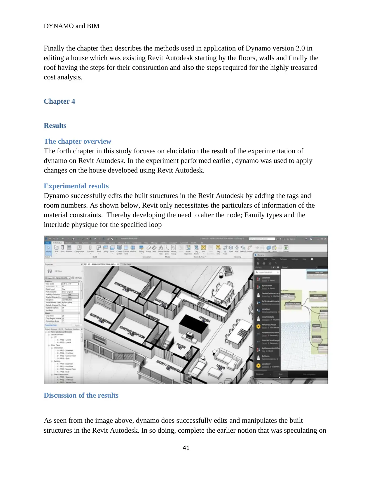
DYNAMO and BIM
Finally the chapter then describes the methods used in application of Dynamo version 2.0 in
editing a house which was existing Revit Autodesk starting by the floors, walls and finally the
roof having the steps for their construction and also the steps required for the highly treasured
cost analysis.
Chapter 4
Results
The chapter overview
The forth chapter in this study focuses on elucidation the result of the experimentation of
dynamo on Revit Autodesk. In the experiment performed earlier, dynamo was used to apply
changes on the house developed using Revit Autodesk.
Experimental results
Dynamo successfully edits the built structures in the Revit Autodesk by adding the tags and
room numbers. As shown below, Revit only necessitates the particulars of information of the
material constraints. Thereby developing the need to alter the node; Family types and the
interlude physique for the specified loop
Discussion of the results
As seen from the image above, dynamo does successfully edits and manipulates the built
structures in the Revit Autodesk. In so doing, complete the earlier notion that was speculating on
41
DYNAMO and BIM
the use of dynamo as an interactive add in built software in Revit Autodesk. The active and
interactive user library and ample workspace that do exist in the dynamo makes the coding
process guileless due to its architectural template. The architectural template is actual detail
that’s makes it an outstanding built engineering add in soft wares (Ritter & Borrmann, 2015).
However, other special aspects of the dynamo such as the ability to check and test building
designs, ease of access to building data and the finally the most central role in the building
design is by allowing the architects to think more mutually and comprehensively inclusive. The
combination of the many small and crucial available in dynamo domain makes it an impeccable
building model (Christenson, 2019)
It also important to note that dynamo algorithm is in line with all the building dimensions.
Dynamo is judged and associated with the third dimension since it produces graphical images
linking it to the X, Y and Z components of the specified dimension. As shown in the previous
chapter dynamo has the basic capability to compact with all the building dimensions as shown:
4th , 5th , 6th and 7th dimension deals with building aspects like time and scheduling of events,
budget concerns; significant building dimension since allow the promoters and the owners to
have a fiscal visualization and the space to plan on the probable man power, machinery and the
best financially suitable construction constituents, focuses on the energy consumption by the
construction; it aims at information the engineers of the need to use efficient data and energy
resources in powering the site, emphases on up keep of the building till its start of demolition
ensuring that all the safety appliances such as the fire extinguishers are on place, proper lighting
condition and any other appliances installed on during the construction phase respectively. The
specification of the 4th, 5th, 6th and 7th building dimensions are refurbished in the designing of the
building architecture where while the architect interacts with the dynamo workspace and library,
performs the cost elements analysis and comprehensive parametric which do focus on the other
building dimensions (Thabet & Miller, 2019).
Parameterization in BIM models
Parameterization is usually done in BIM models to estimate the effects of altering elements
constrains such as the height and the width of the specified building surface for instance the
windows and the doors (Ignatova & Smarsly, 2015). It sought to answer questions such as;
To what extend does the energy distribution gets impacted by altering the Width of the
window?
To what extend does the price gets impacted by altering the Width of the window?
To what extend does the energy distribution gets impacted by altering the height of the
window?
To what extend does the price gets impacted by altering the Width of the window?
To what extend does the energy distribution gets impacted by altering the Width and
height of the window?
To what extend does the energy distribution gets impacted by altering the position of the
window?
42
DYNAMO and BIM
To what extend does the price gets impacted by altering the Width of the window?
To what extend does the price gets impacted by altering the Width and height of the
window?
The questions raised above are in fulfillment of the 5th and the 6th building dimension.
Dynamo has the capacity to handle such building items by just entering the right nodes
into its systems (Zhang and Chang, 2016). Parameterization therefore is an important
aspect in the building dimension.
Chapter 5
Conclusion and Recommendation
This is the last chapter of the thesis and it is apprehensive about the conclusions and the
recommendation; the final thoughts, application and knowledge learned and observed during the
experimentations of this thesis. During the experimentation it is probable that fundamental skills
were learnt and can be used as point of reference when conducting other research on dynamo or
any other related software basing on its capacity and application to handle different roles and
tasks.
Conclusion
Basing on the experiment conducted in this study it was concluded that dynamo can be
used to perform interim changes in the built models that already existing in the Revit
Autodesk. The experiment performed earlier succeeded in the editing the built structure
in the Revit using the dynamo by adding tags and names to different rooms that were
already in the house, this was based on the 3rd dimension of the BIM. The success of
BIM in editing and manipulation the 3rd dimension lead to conclusion that the dynamo
can also deal with the other building dimension. It was also concluded that 4th , 5th , 6th
and 7th dimension compacts with building aspects like time and scheduling of events,
budget concerns; significant building dimension since allow the promoters and the
owners to have a fiscal visualization and the space to plan on the probable man power,
machinery and the best financially suitable construction constituents, focuses on the
energy consumption by the construction; it aims at information the engineers of the need
to use efficient data and energy resources in powering the site, emphases on up keep of
the building till its start of demolition ensuring that all the safety appliances such as the
fire extinguishers are on place, proper lighting condition and any other appliances
installed on during the construction phase respectively.
On further probing it was concluded that the Dynamo mostly used with Autodesk Revit
and Vasari do enable engineers and constructors to design graphical images in the
workspace with the use of computational design and automation processes assisted by a
functional nodes that are task specified. By providing users with powerful functions such
43
Paraphrase This Document
Need a fresh take? Get an instant paraphrase of this document with our AI Paraphraser
DYNAMO and BIM
as mathematical maneuvers, gradients, listing, scripting, geometry handling, Excel data
importation and exportation, it empowers them to perform sophisticated data
manipulation, execution of relational structure, and comprehensive geometric controls by
sourcing, reading and writing data from external sources and editing and manipulating
data to fit, functions that are impossible when using a conventional modeling interface.
It was concluded that the only reason for the foundation of Revit and Dynamo was
because the need of allowing the building engineers multiple designing architectures
basing on different needs of the construction wants. Using dynamo computation
framework industrial engineers can formulate over a hundred pieces of designs upon
which the constructors can decide the best option to go for. Dynamo can be used to
create different designs can do enigma people. It is a powerful tool which has
inaugurated a never ceasing revolution in the building world with its glazing patterns.
Recommendation to the study
Basing on the conclusions issued above, and after keenly observing the excellent
performance of the dynamo. It was recommended that all the new building structures that
are about to be raised, should be built with the ample support of the dynamo and Revit
Autodesk application software. The two systems allow the architects and the promoters
of the new built structure to comprehensive and mutually exhaustively to think about
what they are about to build. As a result, better, strong, long lasting, stable, stout and
more importantly beautiful and unique built structure will be developed.
Taking note of the BIM and its 5 building dimension it was recommended to the
architects and the promoters of the new built structures to adhere to them. The 3rd, 4th, 5th,
6th and 7th dimension of building concerns of the all the important aspects that need to be
considered before raising a safe and solid structure. Earlier in this thesis, it was exposed
that up 62% of building structures had their construction activities hampered by financial
reasons, such ineffectiveness can be controlled by strictly adhering the 5th building
dimension with the conduction of the element cost analysis.
List of reference
Ahn, S.,& Yang, Y. (2011, June). Object-oriented modeling of construction operations for
schedule-cost integrated planning based on BIM. In Proceedings of the International Conference
on Computing in Civil and Building Engineering, Nottingham.
Bazafkan, E., 2017. Assessment of Usablity and Usefulness of New Building Performance
Simulation Tool in Architectural Design Process. Vinenna University of Technology.
Becerik-Gerber, & Ku, K. (2011). The pace of technological innovation in architecture,
engineering, and construction education: integrating recent trends into the curricula.
44

DYNAMO and BIM
Bestley, R. and Noble, I., 2016. Visual research: An introduction to research methods in graphic
design. Bloomsbury Publishing.
Booth, T., & Stumpf, S. (2013, June). End-user experiences of visual and textual programming
environments for Arduino. In International symposium on end user development (pp. 25-39).
Springer, Berlin, Heidelberg.
Borges, M. M. (2019). Visual research: An introduction to research methods in graphic design.
Bloomsbury Publishing.
Borges, M.M., 2018. BIM modelling automation on reinforcement detailing of slabs (Doctoral
dissertation).
Borland, T.D., 2019. An automated method mapping parametric features between computer
aided design software (Doctoral dissertation, Brunel University London).
Burnett, M. M. (2011). Visual programming. Wiley Encyclopedia of Electrical and Electronics
Engineering.
Cantrell, B. and Mekies, A. eds., 2018. Codify: Parametric and computational design in
landscape architecture. Routledge.
Chi, H. L., & Wang, X. (2013). Research trends and opportunities of augmented reality
applications in architecture, engineering, and construction. Automation in construction, 33, 116-
122.
Christenson, M. (2019). Testing the relevance of parameterization to architectural
epistemology. Architectural Science Review, 52(2), 135-141.
Cruz, T.V., 2018. Virtual reality in the architecture, engineering and construction industry
proposal of an interactive collaboration application.
Danner, R., 2016. Architectural Modeling in Revit: The BIM House 2015-Volume 2.
de Mattos Nascimentoa, D.L., 2016. Project automation application with lean philosophy at the
construction of oil refining unit. Brazilian Journal of Operations & Production
Management, 13(1), pp.124-136.
De Wilde, P., and Garrigós, A.G. eds., 2019. Building Information Modelling (BIM) in Design,
Construction and Operations III (Vol. 192). WIT Press.
Denis, F. (2014). Tool for augmented parametric building information modelling for
transformable buildings. Brussels Faculty of Engineering BRUFACE-ULB/VUB.
Dutt, F., and Swartz, M., 2016. Interactive Glare Visualization Model for an Architectural
Space. Between Computational Models and Performative Capacities., 19(97).
45
DYNAMO and BIM
Elsayed, K., & Squasi, F. (2017). Low-Cost Housing. SharingofComputableKnowledge!, 167.
Fakhrutdinov, P., 2018. Designing with Autodesk Revit.
Felleisen, M., and Krishnamurthi, S., 2018. How to design programs: an introduction to
programming and computing. MIT Press.
Gamil, M., 2017. Mapping between BIM and lean-construction.
Garber, R., 2017. Workflows: Expanding Architecture's Territory in the Design and Delivery of
Buildings. John Wiley & Sons.
Garcia Fritz, J., 2019. Automated Comprehensiveness: Sectional Practices and the Misuse of
Revit. Building Technology Educator's Society, 2019(1), p.14.
Högberg, S. and SPARGREN, V., 2017. Effects of Implementing Virtual Design and
Construction to a Project Organisation A multiple case study in the construction sector (Master's
thesis).
Holzer, D., 2016. The BIM manager's handbook: guidance for professionals in architecture,
engineering, and construction. John Wiley & Sons.
Huang, L. (2018). Revit Plugins for Electrical Engineering Improvements in Buildings: Lighting
Power Density and Electrical Equipment Placement (Doctoral dissertation, University of
Southern California).
Ibrahim, M., & Schipporeit, G. (2014, September). Two approaches to BIM: a comparative
study. In eCAADe Conference (Vol. 22, pp. 610-616).
Ignatova, E,.& Smarsly, K. (2015). Parametric geometric modeling in construction planning
using industry foundation classes.
Imtaar, M., 2016. Complete Technical BIM Project using Autodesk Revit: Architecture-
Structure-MEP. CreateSpace Independent Publishing Platform.
Jang, H.,& Kim, J. (2011). Labour productivity model for reinforced concrete construction
projects. Construction Innovation.
Johansen, S.C. and Kjærvik, H., 2018. Building Information Modelling in the Production
Process: A Holistic Case Study of Routine Changes in the Norwegian Construction
Industry (Master's thesis, Handelshøyskolen BI).
Johnson, B.R., 2015. One BIM to Rule Them All: Future Reality or Myth?. Building Information
Modeling: BIM in Current and Future Practice, pp.173-185.
46
Secure Best Marks with AI Grader
Need help grading? Try our AI Grader for instant feedback on your assignments.
DYNAMO and BIM
Kensek, K. (2015). Visual programming for building information modeling: energy and shading
analysis case studies. Journal of Green Building, 10(4), 28-43.
Kensek, K. M. (2014). Integración de sensores medioambientales con BIM: casos de estudio
usando Arduino, Dynamo, y Revit API. Informes de la Construcción, 66(536), 044.
Kensek, K. M. (2014). Integration of Environmental Sensors with BIM: case studies using
Arduino, Dynamo, and the Revit API.
Kensek, K. M. (2017). Integration of Environmental Sensors with BIM: case studies using
Arduino, Dynamo, and the Revit API.
Kranz, M., 2016. Building the internet of things: Implement new business models, disrupt
competitors, transform your industry. John Wiley & Sons.
Li, R.Y.M., 2018. Building Information Modelling and Construction Safety. In An Economic
Analysis on Automated Construction Safety (pp. 47-72). Springer, Singapore.
Liu, W.,& Li, Y. (2014). Retracted: using BIM to improve the design and construction of bridge
projects: a case study of a long-span steel-box arch bridge project.
Madanayake, U. and Egbu, C., 2017, November. A Systematic Review for the Challenges
Related to the Implementation of Building Information Modelling, Big Data Analytics and
Internet of Things (BBI) in the Construction Sector. In International Conference on Sustainable
Futures-ICSF 2017. Applied Science University Bahrain.
MANJUNATHA, R., 2019. Building information modelling (BIM). Defining user's profiles for
accessing the BIM management system for efficient renovation in building.
Marcos, C.L. ed., 2018. Graphic Imprints: The Influence of Representation and Ideation Tools in
Architecture. Springer.
Mayo, G., and Smith, D.K., 2018, March. Implementation of the BIM body of knowledge (BOK)
framework for program planning in academia. In Proceedings of the 12th BIM Academic
Symposium & Job Task Analysis Review, Orlando, FL (pp. 2-9).
Mengana, S. and Mousiadis, T., 2016. Parametric BIM: Energy Performance Analysis Using
Dynamo for Revit.
Meža, S., & Dolenc, M. (2015). Measuring the potential of augmented reality in civil
engineering. Advances in engineering software, 90, 1-10.
Minsky, M. and Papert, S.A., 2017. Perceptrons: An introduction to computational geometry.
MIT press.
47
DYNAMO and BIM
Nawari, N. O. (2012). BIM standard in off-site construction. Journal of Architectural
Engineering, 18(2), 107-113.
Nemirovsky, D.A., 2017. Improving heterogeneous system efficiency: architecture, scheduling,
and machine learning.
Nezamaldin, D. (2019). Parametric design with Visual programming in Dynamo with Revit: The
conversion from CAD models to BIM and the design of analytical applications.
Nguyen, N. S. T. (2020). Shape grammar based adaptive building envelopes: Towards a novel
climate responsive facade systems for sustainable architectural design in Vietnam.
Nikolic, D., & Messner, J. I. (2011). Educational simulation in construction: Virtual construction
simulator. Journal of Computing in Civil Engineering, 25(6), 421-429.
Osello, A. (2012). Il futuro del disegno con il BIM per ingegneri e architetti, The future of
Drawing with BIM for Engineers and Architects. Palermo: Dario Flaccovio Editore.
Ritter, F., Geyer, P., & Borrmann, A. (2015, October). Simulation-based decision-making in
early design stages. In 32nd CIB W78 Conference, Eindhoven, The Netherlands (pp. 27-29).
Sacks, R., & Pikas, E. (2013). Building information modeling education for construction
engineering and management. I: Industry requirements, state of the art, and gap analysis. Journal
of Construction Engineering and Management, 139(11), 04013016.
Sacks, R., and Teicholz, P., 2018. BIM handbook: a guide to building information modeling for
owners, designers, engineers, contractors, and facility managers. John Wiley & Sons.
Sandzhiev, N.V. and DA, S., (2016). Dynamo platform for automation Revit.
Sanguinetti, P., & Eastman, C. (2012). General system architecture for BIM: An integrated
approach for design and analysis. Advanced Engineering Informatics, 26(2), 323-331.
Sanguinetti, P., & Eastman, C. (2012). General system architecture for BIM: An integrated
approach for design and analysis. Advanced Engineering Informatics, 26(2), 317-333.
Seghier, T. E., & Samuel, W. O. (2017). Building envelope thermal performance assessment
using visual programming and BIM, based on ETTV requirement of Green Mark and
GreenRE. International Journal of Built Environment and Sustainability, 4(3).
Shigaki, J.S.I., 2016. Understanding the context for the implementation of Building Information
Modelling in engineer-to-order prefabricated building systems.
Shin, J., Siegwart, R., & Magnenat, S. (2014). Visual programming language for Thymio II
robot. In Conference on Interaction Design and Children (IDC'14). ETH Zürich.
48
DYNAMO and BIM
Sieffert, Y., & Daudon, D. (2014). Sustainable construction with repurposed materials in the
context of a civil engineering–architecture collaboration. Journal of Cleaner Production, 67,
125-138.
Singh, A., 2017. Creative systems in structural and construction engineering. Routledge.
Smith, P. (2014). BIM implementation–global strategies. Procedia Engineering, 85, 482-492.
Solihin, W., & Eastman, C. (2015). Classification of rules for automated BIM rule checking
development. Automation in construction, 53, 69-82.
Thabet, W. and Lucas, J., 2019. Using Dynamo for Model-Based Delivery of Facility Asset
Data.
Thabet, W., & Miller, D. (2019). Linking Revit Facility Life-Cycle Data to ARCHIBUS–A Case
Study of an Academic Institution.
Thomson, C.P.H., 2016. From Point Cloud to Building Information Model: Capturing and
Processing Survey Data Towards Automation for High Quality 3D Models to Aid a BIM
Process (Doctoral dissertation, UCL (University College London)).
Thorsen, L.T., 2016. Multi-factor Authentication using Secure Elements: Enhancing the
Usability with new Web APIs (Master's thesis).
Veloso, P., and Scheeren, R., 2018. From the generation of layouts to the production of
construction documents: An application in the customization of apartment plans. Automation in
Construction, 96, pp.224-235.
Wang, B., 2014. End user oriented BIM enabled multi-functional virtual environment supporting
building emergency planning and evacuation (Doctoral dissertation, Cardiff University).
Weinberg, N., 2019. Computers in the information society. Routledge.
Wetzel, E.M. and Thabet, W.Y., 2018. A case study towards transferring relevant safety
information for facilities maintenance using BIM.
Woo, J. H. (2016). BIM (building information modeling) and pedagogical challenges.
In Proceedings of the 43rd ASC national annual conference (pp. 12-14).
Yadav, S. and Kanade, G., 2018. Application of Revit as Building Information Modeling (BIM)
for Integrated Project Delivery (IPD) to Building Construction Project-A.
Yan, J., 2017. CFD Visualization: A Case Study for Using a Building Information Modeling with
Virtual Reality (Doctoral dissertation, University of Southern California).
49
Paraphrase This Document
Need a fresh take? Get an instant paraphrase of this document with our AI Paraphraser

DYNAMO and BIM
Zaker, R. and Coloma, E., 2018. Virtual reality-integrated workflow in BIM-enabled projects
collaboration and design review: a case study. Visualization in Engineering, 6(1), p.4.
Zhang, S & Venugopal, M. (2013). Building information modeling (BIM) and safety: Automatic
safety checking of construction models and schedules. Automation in Construction, 29, 183-195.
Zhang, Y., and Chang, L., 2016, July. Integration application system of Chinese wooden
architecture heritages based on BIM. In 2016 International Conference on Logistics, Informatics
and Service Sciences (LISS) (pp. 1-8). IEEE.
Takim, R,.& Nawawi, A. H. (2013). Building Information Modeling (BIM): A new paradigm for
quality of life within Architectural, Engineering and Construction (AEC) industry. Procedia-
social and behavioral sciences, 101, 23-32.
50
1 out of 50
Your All-in-One AI-Powered Toolkit for Academic Success.
+13062052269
info@desklib.com
Available 24*7 on WhatsApp / Email
![[object Object]](/_next/static/media/star-bottom.7253800d.svg)
Unlock your academic potential
© 2024 | Zucol Services PVT LTD | All rights reserved.