Guided Gear Design for an Escalator
VerifiedAdded on 2019/09/16
|4
|1215
|572
Project
AI Summary
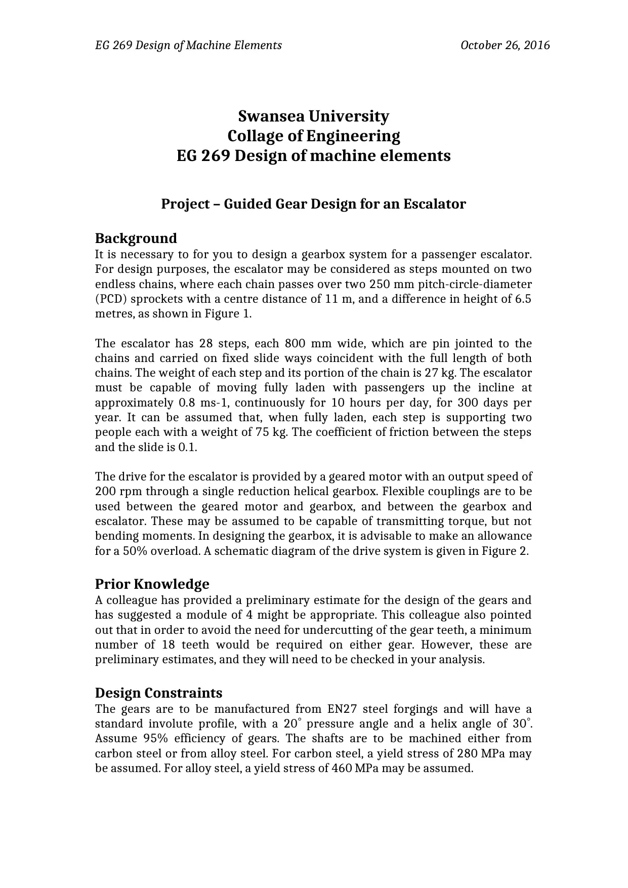
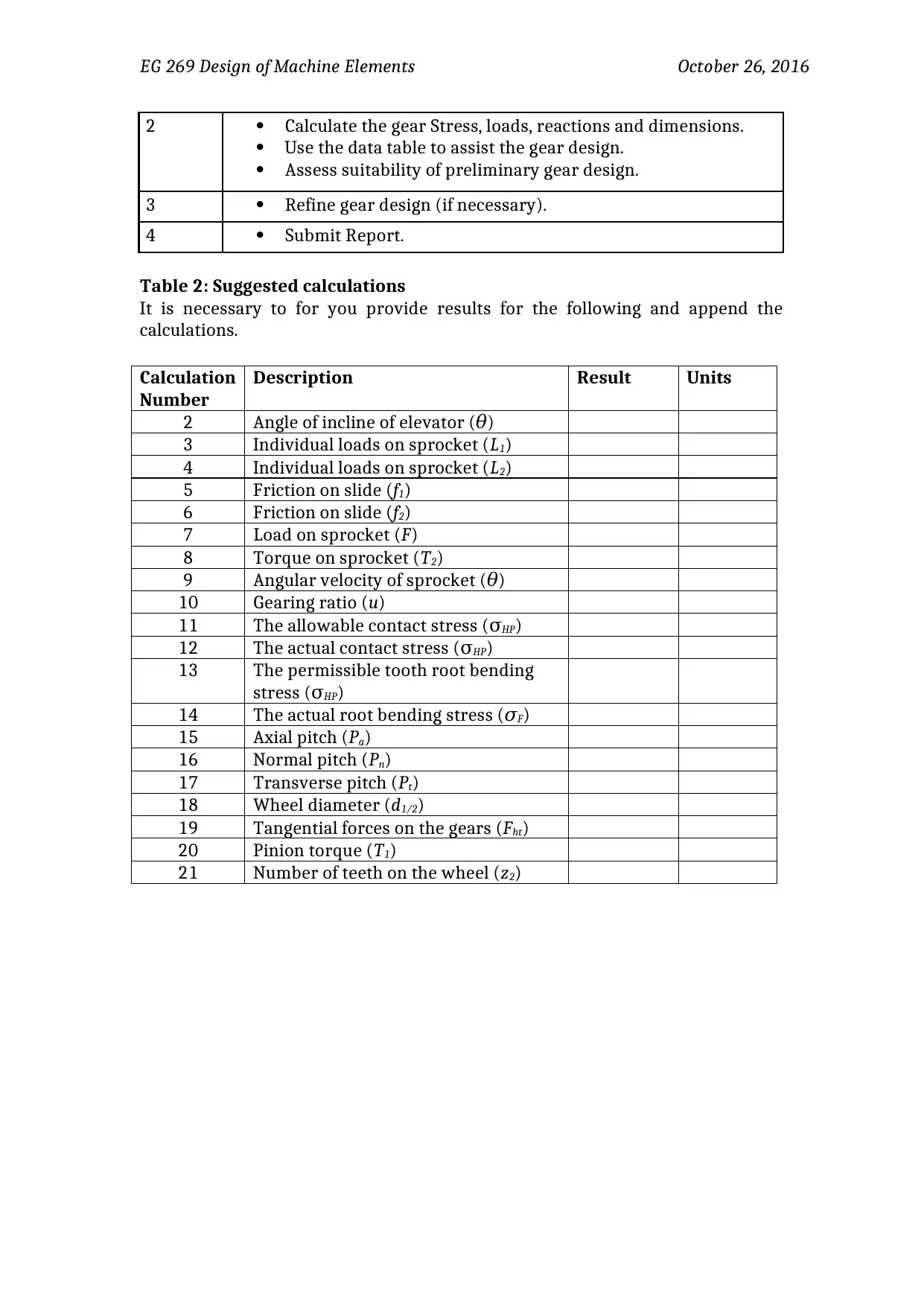
Design a gearbox system for an escalator, considering its components, constraints, and requirements. The task involves estimating loads imposed on the escalator, calculating torque required from the gearbox, determining gear forces, assessing face width of gears, checking preliminary estimates, suggesting modifications if necessary, and listing assumptions.
Contribute Materials
Your contribution can guide someone’s learning journey. Share your
documents today.


1 out of 4
Related Documents
Your All-in-One AI-Powered Toolkit for Academic Success.
+13062052269
info@desklib.com
Available 24*7 on WhatsApp / Email
![[object Object]](/_next/static/media/star-bottom.7253800d.svg)
© 2024 | Zucol Services PVT LTD | All rights reserved.