Electrical Safety in Buildings

Verified

Added on  2020/05/28

|7
|916
|120
AI Summary
The assignment delves into the principles of electrical safety within building structures. It discusses 'electrical separation,' a method to isolate systems from each other to prevent shock hazards. The text explains how double-wound transformers break the link to the earth in bathrooms for enhanced safety. Further, it explores various types of protective conductors, their applications in different areas of a building, and examples of supplementary equipotential bonding, functional earth, and earthing conductors. The assignment also touches upon isolation and switching mechanisms for maintenance purposes and functional switching in specific areas like pool equipment rooms.

Contribute Materials

Your contribution can guide someone’s learning journey. Share your documents today.
Document Page
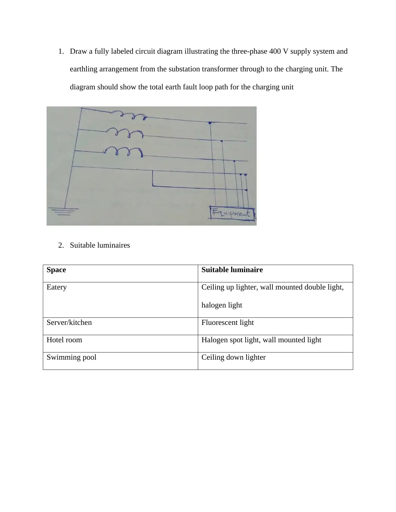
1. Draw a fully labeled circuit diagram illustrating the three-phase 400 V supply system and
earthling arrangement from the substation transformer through to the charging unit. The
diagram should show the total earth fault loop path for the charging unit
2. Suitable luminaires
Space Suitable luminaire
Eatery Ceiling up lighter, wall mounted double light,
halogen light
Server/kitchen Fluorescent light
Hotel room Halogen spot light, wall mounted light
Swimming pool Ceiling down lighter

Secure Best Marks with AI Grader

Need help grading? Try our AI Grader for instant feedback on your assignments.
Document Page
3. Circuit protection devices
Circuit Breakers: This device would prevent the breakage of an electrical circuit that may result
from an overcurrent, which is in most cases associated with either an overload or a short circuit.
Circuit breakers disrupt the flow of current upon detection of a fault.
Electronic Fuses: A fuse is a resistor of low resistance, which offers protection in case of an
overload on an electrical circuit, which may result from short-circuiting, failure of the device, or
overloading of the circuit.
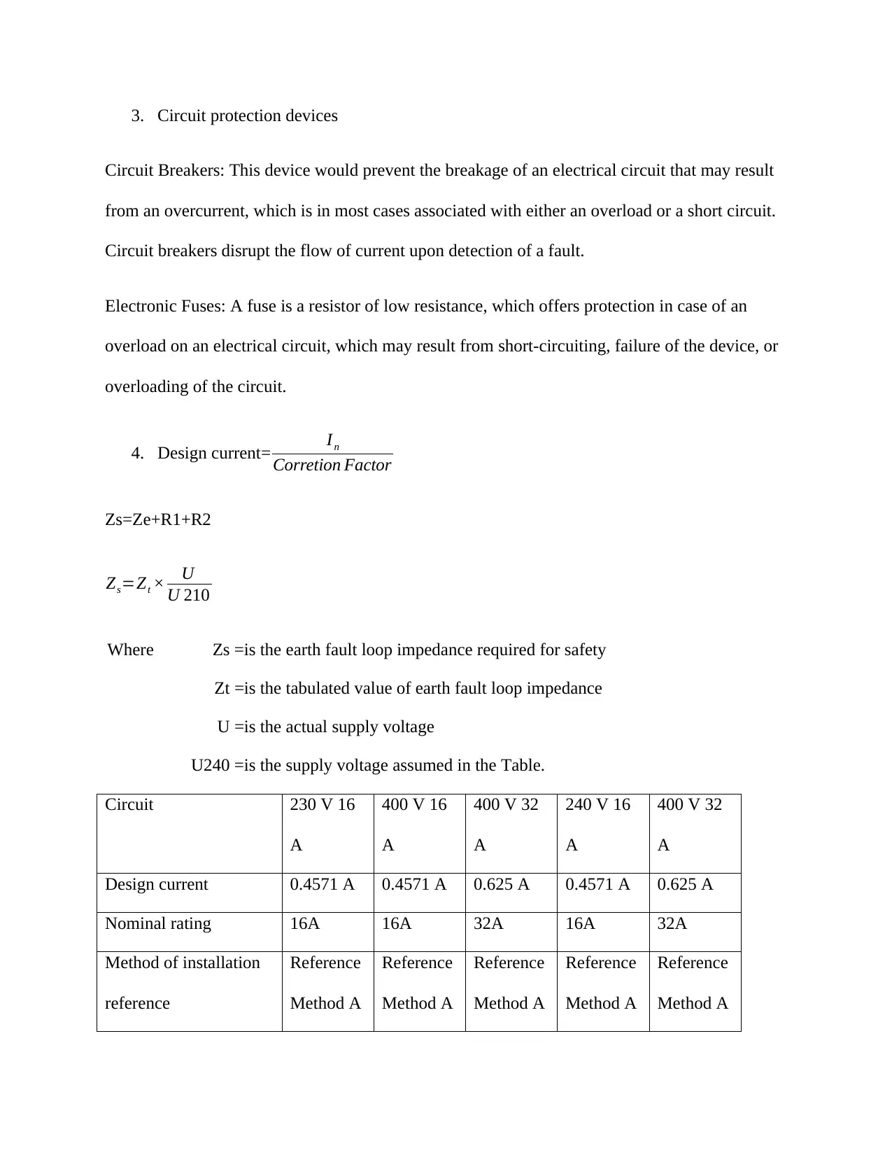
4. Design current= In
Corretion Factor
Zs=Ze+R1+R2
Zs=Zt × U
U 210
Where Zs =is the earth fault loop impedance required for safety
Zt =is the tabulated value of earth fault loop impedance
U =is the actual supply voltage
U240 =is the supply voltage assumed in the Table.
Circuit 230 V 16
A
400 V 16
A
400 V 32
A
240 V 16
A
400 V 32
A
Design current 0.4571 A 0.4571 A 0.625 A 0.4571 A 0.625 A
Nominal rating 16A 16A 32A 16A 32A
Method of installation
reference
Reference
Method A
Reference
Method A
Reference
Method A
Reference
Method A
Reference
Method A
Document Page
Rating factors
applicable
20 A 20 A 40 A 20 A 40 A
Minimum csa of live
conductors
13.5 mm2 13.5 mm2 15.5 mm2 13.5 mm2 15.5 mm2
Actual voltage drop 45.92 45.92 58.880 45.92 58.88
Maximum permissible
connection time
0.4 s 0.4 s 5 s 0.4 s 5 s
Earth fault loop
impedance
1.96 ohms 3.38 ohms 3.38 ohms 1.96 ohms 3.38 ohms
Maximum earth loop
impedance
2.87 ohms 2.87 ohms 1.84 ohms 2.87 ohms 1.84 ohms
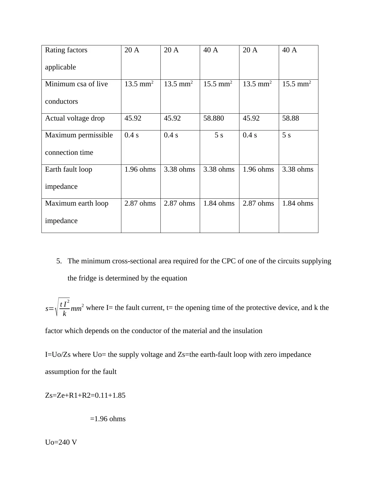
5. The minimum cross-sectional area required for the CPC of one of the circuits supplying
the fridge is determined by the equation
s= t I 2
k mm2 where I= the fault current, t= the opening time of the protective device, and k the
factor which depends on the conductor of the material and the insulation
I=Uo/Zs where Uo= the supply voltage and Zs=the earth-fault loop with zero impedance
assumption for the fault
Zs=Ze+R1+R2=0.11+1.85
=1.96 ohms
Uo=240 V
Document Page
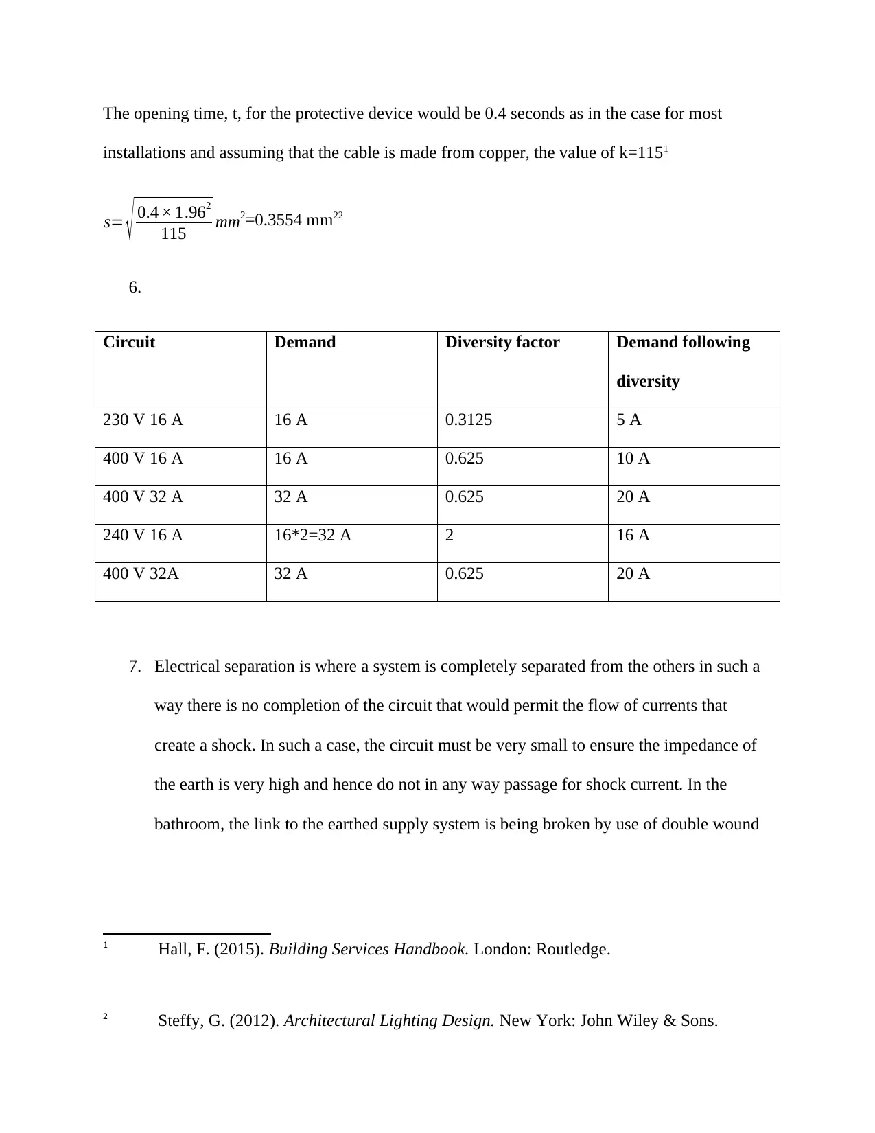
The opening time, t, for the protective device would be 0.4 seconds as in the case for most
installations and assuming that the cable is made from copper, the value of k=1151
s= 0.4 × 1.962
115 mm2=0.3554 mm22
6.
Circuit Demand Diversity factor Demand following
diversity
230 V 16 A 16 A 0.3125 5 A
400 V 16 A 16 A 0.625 10 A
400 V 32 A 32 A 0.625 20 A
240 V 16 A 16*2=32 A 2 16 A
400 V 32A 32 A 0.625 20 A
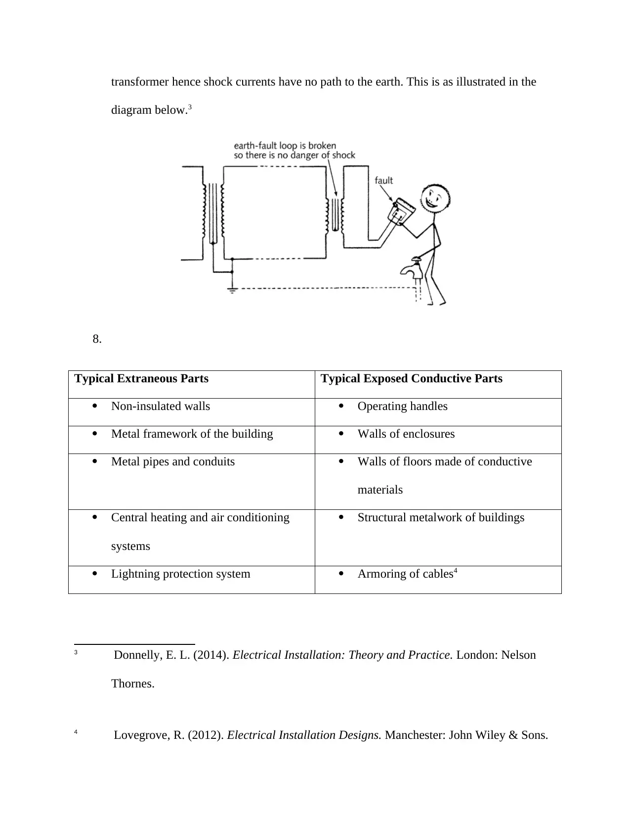
7. Electrical separation is where a system is completely separated from the others in such a
way there is no completion of the circuit that would permit the flow of currents that
create a shock. In such a case, the circuit must be very small to ensure the impedance of
the earth is very high and hence do not in any way passage for shock current. In the
bathroom, the link to the earthed supply system is being broken by use of double wound
1 Hall, F. (2015). Building Services Handbook. London: Routledge.
2 Steffy, G. (2012). Architectural Lighting Design. New York: John Wiley & Sons.

Secure Best Marks with AI Grader

Need help grading? Try our AI Grader for instant feedback on your assignments.
Document Page
transformer hence shock currents have no path to the earth. This is as illustrated in the
diagram below.3
8.
Typical Extraneous Parts Typical Exposed Conductive Parts
Non-insulated walls Operating handles
Metal framework of the building Walls of enclosures
Metal pipes and conduits Walls of floors made of conductive
materials
Central heating and air conditioning
systems
Structural metalwork of buildings
Lightning protection system Armoring of cables4
3 Donnelly, E. L. (2014). Electrical Installation: Theory and Practice. London: Nelson
Thornes.
4 Lovegrove, R. (2012). Electrical Installation Designs. Manchester: John Wiley & Sons.
Document Page
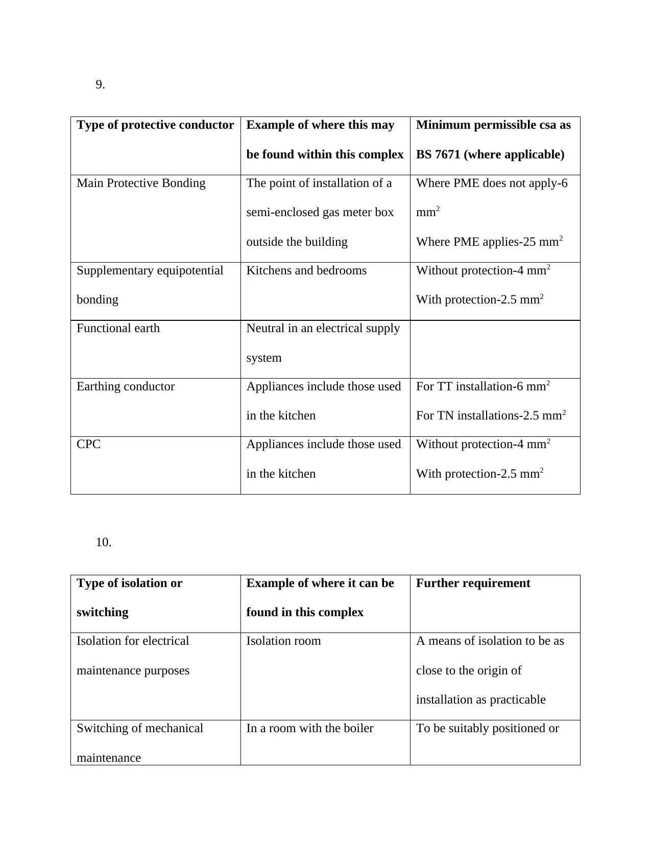
9.
Type of protective conductor Example of where this may
be found within this complex
Minimum permissible csa as
BS 7671 (where applicable)
Main Protective Bonding The point of installation of a
semi-enclosed gas meter box
outside the building
Where PME does not apply-6
mm2
Where PME applies-25 mm2
Supplementary equipotential
bonding
Kitchens and bedrooms Without protection-4 mm2
With protection-2.5 mm2
Functional earth Neutral in an electrical supply
system
Earthing conductor Appliances include those used
in the kitchen
For TT installation-6 mm2
For TN installations-2.5 mm2
CPC Appliances include those used
in the kitchen
Without protection-4 mm2
With protection-2.5 mm2
10.
Type of isolation or
switching
Example of where it can be
found in this complex
Further requirement
Isolation for electrical
maintenance purposes
Isolation room A means of isolation to be as
close to the origin of
installation as practicable
Switching of mechanical
maintenance
In a room with the boiler To be suitably positioned or
Document Page
durably marked
May need to be secured in the
open position
Functional switching Pool equipment room Circuits that contain stored
energy may need to be
discharged
1 out of 7
circle_padding
hide_on_mobile
zoom_out_icon
[object Object]

Your All-in-One AI-Powered Toolkit for Academic Success.

Available 24*7 on WhatsApp / Email

[object Object]