Electric Vehicle Revolution: Battery Management and Power System Design
VerifiedAdded on 2023/06/10
|29
|6693
|499
AI Summary
This report discusses the reliability and design of electric cars, specifically the power management system which includes the battery management system, controller, and converter circuit. It covers technical problem-solving techniques, wear reduction methods, and hardware considerations. The report discusses the battery monitoring unit, control area network, thermal management systems, and the components of an electric vehicle.
Contribute Materials
Your contribution can guide someone’s learning journey. Share your
documents today.
MAINTENANCE ENGINEERING
PRODUCTION SYSTEM
By Name
Course
Instructor
Institution
Location
Date
PRODUCTION SYSTEM
By Name
Course
Instructor
Institution
Location
Date
Secure Best Marks with AI Grader
Need help grading? Try our AI Grader for instant feedback on your assignments.
Contents
EXECUTIVE SUMMARY...................................................................................................................3
INRODUCTION...................................................................................................................................4
AIMS AND OBJECTIVES...................................................................................................................5
LITERATURE REVIEW......................................................................................................................6
Battery Monitoring Unit....................................................................................................................8
Control Area Network.....................................................................................................................10
Thermal Management Systems........................................................................................................11
The components of an electrical Vehicle.........................................................................................13
METHODOLOGY..............................................................................................................................14
Technical problem-solving techniques (TRIZ)................................................................................15
Wear Reduction Methods................................................................................................................17
Consideration of Hardware..............................................................................................................17
RESULTS AND DISCUSSIONS........................................................................................................21
CONCLUSION AND RECOMMENDATIONS.................................................................................24
CONCLUSION...................................................................................................................................25
REFERENCES....................................................................................................................................26
EXECUTIVE SUMMARY
The electric vehicle revolution is rapidly following the transformation as witnessed with the
solar rooftops used globally This has been followed by the revolution in the prices of the
battery that has equally fallen. The electric vehicles that have been manufactured in the
countries such as United States have significantly led to the cheaper options as opposed to the
earlier models. The use of the Pulse Width Modulation Motor Control circuits that is
inclusive of the battery management system is in the field and category application of the cars
that are powered by the battery. In the future electrical engineering applications, the use of
the battery powered cars will take the centre of all the applications.
Urban car travel is best suited to the use of the electric vehicles. In the cases where the
longer journeys are required and to those users who may not have access to the home
charging system, the designed model includes the public utility Reid, MacDonald and Du
2013. It is therefore clear that the users will properly utilise this option so as to save on the
cost of the fuel and enjoy the most convenient charging. Only those nations that put a lot of
effort to the use of the electric cars may stand the chance of survival in the coming
competitive engineering environment. This technology has been commonly being referred to
the Proton Saga EV Green Propulsion. It is of the general opinion that the execution of this
particular project will significantly contribute towards the technological development in the
field of the electronics in the respective countries. This becomes the most important
component in the economy sector Wästlund et al 2015.
In the design of the electric vehicle which is commonly known as the EV design, there is a
very vital role or the significant duty played by the power management and the controller
system. The controller system will serve as the brain of the system and while working
together with the power system, they ensure that the system component or the electric car
moves smoothly and the required order. The controller functions to regulate the main
contractor and have it disconnected at times when there is need to do so. This also puts into
the consideration the appropriate safety measures while reversing the contactor. These
activities help in the powering of the vacuum pumps of the electrical vehicle components or
the parts including the toaster heater contactor.
INRODUCTION
The term Electric Vehicle (EV) has been defined in this particular project as the passenger
vehicles basically cars that are less than 3.5 tonnes in weight. In some cases, the other
automobiles like buses are mention although all the attention focusses on the car. The
management of the power system will ensure that there is a well distribution of power to help
in the achieving of the maximum transfer effected power management system usually
constitutes the following components; the converter circuit, the circuit of charging, the motor
drive and the base circuit drive. In this particular report, the emphasis is put on the reliability
of the electric cars, the design. The design component that focuses on the power management
which is inclusive of the controller and the converter circuit.
The electric buses also had the model that was similar to the electric cars. The intention here
was to explore the conversion of the urban fleet in most of the towns and cities to the electric
option. It was found out that if other factors are held constant, the idea of shifting to 100
percent electric option will contribute significantly to the economy of the countries.
Secure Best Marks with AI Grader
Need help grading? Try our AI Grader for instant feedback on your assignments.
Figure 1 projected utility of the electric car extracted from Wilson, 2013
AIMS AND OBJECTIVES
The project checks whether;
1 The electric personal car utility is technically possible and affordable and also the
possibility of achieving this in the next ten years.
2 The electric cars travel is comparable to the present system of the transport in terms of the
cost, reliability among other things.
The whole project basically focusses on the development of a light weight electric vehicle
commonly referred to as EVs that uses brushless direct current motor type. The study covers
on the properties of these components that includes the working principles of the electrical
vehicle
LITERATURE REVIEW
The idea behind this initiative is to have a fully functioning electrical vehicle that does not
make emissions to the environment. The battery management system is a key technology
involved here in order to have this particular project met, the proton is given much attention
is given to the heart or the Lithium balance. The Lithium balance battery is arranged with
plug in it so that it is having the play concept. The powering mechanism is already taken care
of in many designs. However, there is need to develop a system that is used to monitor the
battery. The parameters of the battery including charging and discharging.
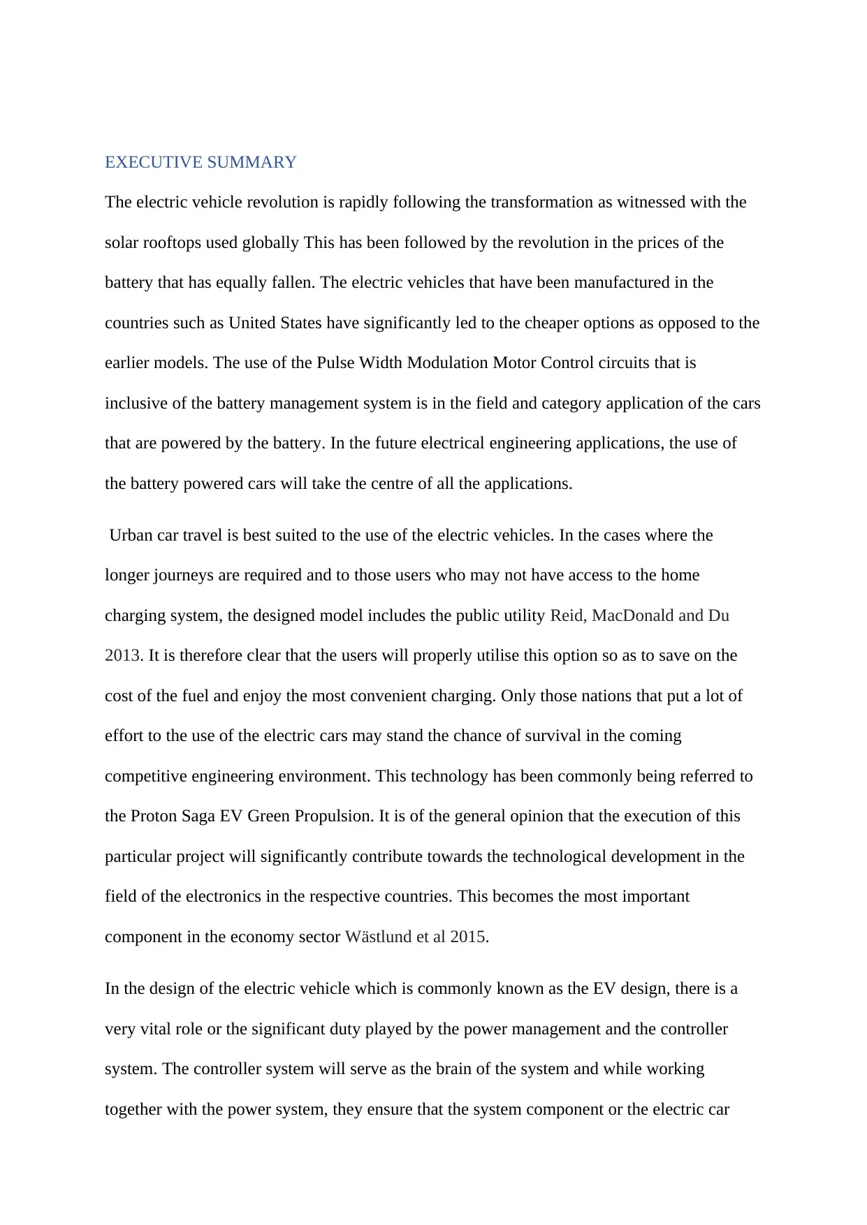
Figure 2 a public charging area of the electric car extracted from Wilkinson and Light 2014
The monitoring values of the voltage, the current flowing, the battery internal resistance and
ambient temperature. The person controlling the car should be in the position of providing
proper protection to the system. This is achieved by ensuring there is an appropriate
production of sound as a way of alerting the operator or electronically disconnecting the
battery from the load in case any of the parameters exceeds its limit. The aims of having a
battery management system are very many.
The battery management system is inside the Electrical Vehicle that protect the Lithium
Battery from the interference or damage to the cells Valero-Mora et al 2013. This increases
the lifespan of the battery. Maintenance of the state of the battery allows the system to
perform the functions and the specifications that are attached to the system itself. Bojko, 2013
The main application of the battery management is to provide the necessary monitoring and
the required control. This will help in avoiding the damage due to the overrating of the
conditions of the temperature( Porta, Ravarelli and Spaghi 2013) This particular application
is very necessary for the vehicle that works under the harsh conditions or experiencing the
climate differences. Every cell in the automotive has to be protected by ensuring that it is
isolated so that the battery can detect the cause of the fault in the case the external fault
happens. In order to have the system disconnected when the heat generated within the system.
For the non-severe cases an additional fan may be attached in front of this battery.
The secondary main development of the battery management system basically refers to the
state of the charge identification. The operator is provided with the identification of the
amount left over before the subsequent recharge is done. This kind of identification is also
known as Gas Gauge. In this particular design, the SOC will calculate each of the individual
cells that are inside the battery in addition to ensuring that they are not subjected to the
overstressed situations. A battery Monitoring Unit apart from the above-mentioned functions,
the SOC indicator will detect the charging and the discharging conditions thereby making it
much easier for them to monitored in each of the cycle.
Paraphrase This Document
Need a fresh take? Get an instant paraphrase of this document with our AI Paraphraser
Battery Monitoring Unit
This is normally a micro controller that is normally used to control and do the monitoring that
is highly required. In most design 0f the car, there are basically three main building blocks
that should be put into thee consideration. These particular quantities include the BMS, the
battery control unit and finally the controller area network. The Vernicles communication
network system together with its internal configuration management system can be checked
for proper settings. It is important to know that the not all the vehicle parts will be connected
to specifically one point (Wästlund et al 2015)
These systems will usually communicate with the BMS through the CAN which usually
includes the Thermal Management System. Such may include the antitheft devices which has
t5he capability to disable the battery.
The ECU which is also known as Engine Control Unit module may not be required in the
situations where the parameters that concerns the Internal Combustion Engine which may not
be examined This is a microcontroller that is based on the digital system used in the
monitoring of the of the health of the battery bank. This simply means that the BMU will do
the calculation of the capacities of the battery in terms of the efficiency from time to time and
then also monitoring each of the cells at the same time. The reduction in the service duty of
the battery will be determined before the actual failure using the module of the BMU and
even the sub modules. The isolation of the sub module is foe the purposes of going very
proper clarifications.
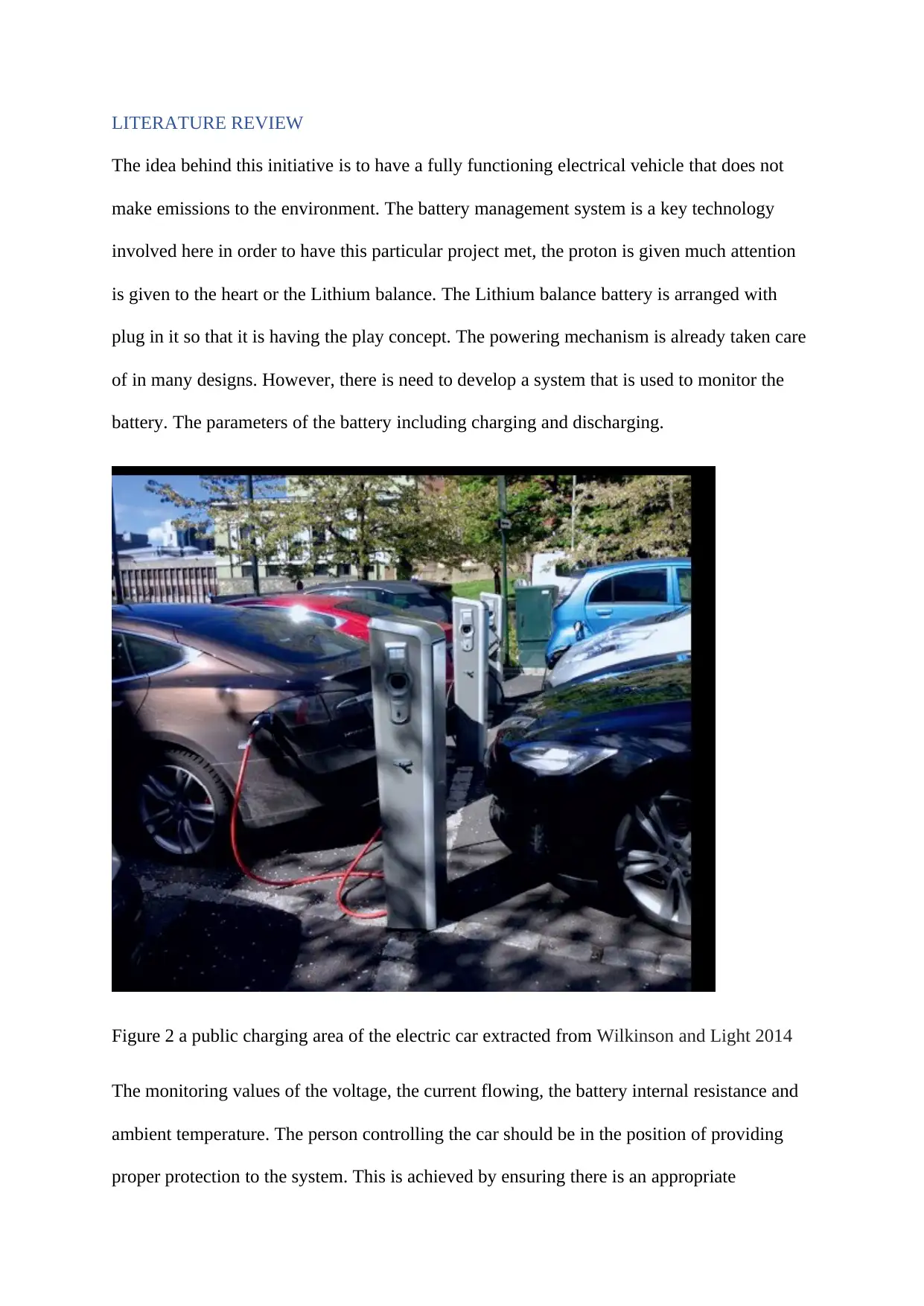
Figure 3 charging the batteries using the solar extracted from Purucker et al 2013
The failure of the battery can be determined easily using the technique which monitors the
voltage of the cell especially during the process of discharging. It is important to remember
that during the determination of the voltage value, the voltage drop should not take too long.
This kind of the failure of the battery is commonly regarded as battery a buse or the misuse of
the battery. The main causes of this obvious failure are the high temperatures and also the use
of the very excessive current amount Porta, Ravarelli and Spaghi 2013.
The other commonly known factors which can lead to the deterioration of the battery are
ageing and even the premature failure that all results from the corrosion and the
manufacturing defects that are known. Other than monitoring the cell that are arranged in the
parallel, there is a process that makes the multiplex architecture to be interfaced to the BMU
so as reduce the cost.
According to this kind of the design, it is only the single analogy or the digital results that
can be subjected to the monitor from time to time. The major disadvantage of this particular
process is that it can only determine the Voltage of a single cell per cycle of the operation.
This therefore means that there is need to provide a very high-speed system that assist in the
monitoring sequentially as the results unfold during charging.
Control Area Network
The control area network was actually developed in the many back so that it could be used to
assist in the vehicle network. The point to point wiring procedure was use to have it installed
by the automotive manufacturers. The disadvantage of this particular wiring technique is that
the many wires are bulky other than being expensive.
Secure Best Marks with AI Grader
Need help grading? Try our AI Grader for instant feedback on your assignments.
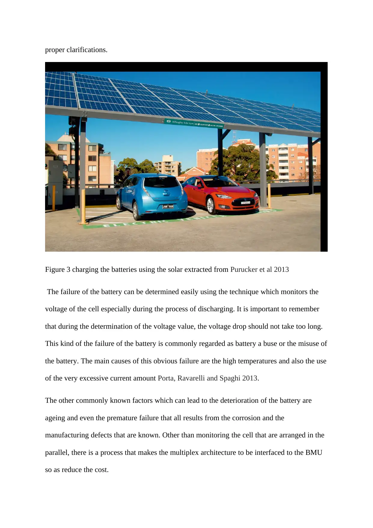
Figure 4; control unit of electric car extracted from Wästlund et al 2015
In the modern technology, the wiring process has been replaced using the technique called
the controller area network in this process cheap mechanism are employed, not very complex
but with the reduction of the weight. It also has very high integrity serial data communication
that regulates the real time control applications. This will be later integrated in the vehicle
network Chien, et al 2015.
Thermal Management Systems
The design of the thermal management system is to help in the monitoring of the temperature
variation that results from the chemistry of the battery. The system serves to perform the
functions such the heating or the cooling of the cells of the battery which will depend exactly
of the curre3nt state of the battery under the monitor of the operator. Most of the test are
carried out in the laboratories that are equipped with the EV urban driving system (Schmitt et
al 2014)
According to this system, the thermal management will lead to the improvement of the
battery mileage and the battery lifespan which can cumulatively go up to more than twenty
percent. The thermal management will always play a very important duty especially during
the process of the charging battery If one was to assume that very high current is delivered to
Figure 5; heat control system of electric car extracted from Ohm et al 2014.
the system of the EV, the temperature issues will be very obvious. The initial stages of the
design protect the battery from the external interference. The insulation process therefore
assists in the enhancing of the generation of the heat during the winter and even the summer
seasons. In the second criteria of the design, the flow of the air has been made possible to
maximise the circulation which later assist in the lowering of the temperature and therefore
achieving the equilibrium the surrounding and the battery itself. The type of the design that is
affected by the environment will be dependent on the prevailing conditions of the
environment where the car is to be operated.
The components of an electrical Vehicle.
The major components of the electrical vehicle include the controller, motor, the power
supply and the channel for the transmission.
Figure 6; schematic layout extracted from De Smet et al 2014
The above figure clearly illustrates the major components of the electrical vehicle. The above
diagram provides the evidence of the power supplies power supply needs to thoroughly
charged up so that the energy level can be restored. This should be done once the available
energy is detected to be approaching near or closer the deletion stage. It is important to
remember that the electric motor is actually driven by the power processing mechanism that
is electronic based Wilkinson and Light 2014. This power system converts the fixed DC
voltage available from the ordinal source into the variable desired voltage which again should
be delivered to the operating vehicle. The power electronic is therefore taken as the driving
force that is dearly required so as to develop an effective and efficient battery with very high
Paraphrase This Document
Need a fresh take? Get an instant paraphrase of this document with our AI Paraphraser
performance. The drive train system may be defined as the electrochemical conversion
linkage system that exist between the vehicle energy source and the wheels. This implies that
it is a combination of both the electronic components and the electrical components of the
complete system.
METHODOLOGY
In order to have the system that is reliable as per the objective of the study the intelligent
electric vehicle controller system, the PICs controller and micro controllers and the Intel atom
board will be used. The Intel board is preferring since it provides the future implementation
opportunities and just like the rest of the processors it uses very little power.
In addition to the building and compiling of the Kernel from the initial which is done through
the repacking of the Ubuntu distribution like any of the incorporated system. The system
must therefore have the installation of the Linux OS of the typical Ubuntu 10.10. When the
operating system is put into the practice and then incorporated as the things becomes much
easier then the position of the drivers and the libraries are taken to be the right ones. There is
a lot of time consumption when it comes to the compilation and the building of the Kernel.
The software issues can actually lead to the unsuccessful results. In order to address this
particular challenge, the operating system must be directly installed in the system Kiefer
Giannopoulos and Raubal,2014.
If the closer attention is given to the storage devices used so as to hold the content of the
operating system. The most commonly used storage devices include the hard disks, floppy
disks, the USB flask among others. Since the system has to be designed for the incorporated
system towards vehicle industries, the most recommended solution would be using the
storage capacity that is large naturally. It is important to note that the system does not have
any mechanical. The absence of the mechanical parts in the SSD mans that the SSD may be
avoided from the interference due to the vehicle that is shaking resulting from the damage
and the uneven surface.
In order to have the project started, there has to be a creation of a bootable flash drive
working with the Linux operating system. Gowda and Kohler 2014 This will however serve
as the unique methods to install the Linux operating system. Since the price of SSD is very
high in the common market, the local hardest will be used instead. A bootable Linux USB
flash becomes created easily when using the Universal- USB-Installer that has been given in
the figure below.
Figure 7: system of the connection extracted from Porta, Ravarelli and Spaghi 2013
A part from that, the input output card expansion used may not be wide in the industries of
the computer though very expensive. For one to overcome this problem, the decision of
saving time and cost are taken into the account. The solution used instead is PIC. In this
particular case the serial has to be taken into the consideration. The chapter that follows gives
the comprehensive design discussion.
Technical problem-solving techniques (TRIZ)
A fast supercharging points are designed to provide at least 350KW of power that will be
capable of charging the compatible vehicles within five to twelve minutes. This should be
done with much consideration to the position of the national grid system. The installation of
such systems will be in such away that the driver cannot be 50 miles away from the charging
station.
The use of induction charging is possibly utilised to fully eliminate the plugging in into the
electric cars. This to some extend is already a reality. The induction or the wireless charging
depends on the availability of the transmitter coil put in the charging pad with the
electromagnetic energy. Power is therefore transmitted to the receiver coil that is positioned
within the object to be charged. This technique can be used in the large-scale production of
the electric cars in which the charging mechanisms will be placed underneath the roads
surface in places such as the parking bay or even in the garage. The receiver pad will be put
in the base of the car that is to be charged.
The use of the wireless road charging that works almost as the induction charging technique
is another option in the solving of the problem. The same induction charging component that
has been bought from the market will be embedded on the road sides at the intervals in order
to ensure that the car will be passing over the charging surfaces continually. The charging
that is done on the move will eliminates the anxiety over range and this will for sure reduce
the charging times.
The use of the supercapacitors will also make an improvement. These capacitors will be
different from the batteries since they produce energy by creating charges that are
electrostatic in nature as opposed to the chemical reaction in the batteries. This technique has
been used to tap a lot of energy from the brake pads This technique however will have a
disadvantage in the sense that capacitors can only hold a charge for few minutes. The
charging will therefore be done after every mile of the travel
Secure Best Marks with AI Grader
Need help grading? Try our AI Grader for instant feedback on your assignments.
Wear Reduction Methods
The internal lubricants alongside the other wear reducing compounds combined to form
plastic resins will be used to minimise the friction. The friction effects have already been
identified as the major threat to the parts of the car that can lead to the loss of the material and
the part failure. This will possibly help in the elimination requirement of applying the
external lubricants. The practice of keeping the moving parts that is the mechanism and
components will enhance the long-time reliability of the electric cars. The removal of the
slip-stick occurrence that is usually witnessed among the plastics so as to ensure there is a
smooth operation of the moving components. This will effectively reduce the squeaks and
other related noises present on the mated surfaces. The abrasion resistance and the vibration
damping all require the use of the wear resistant compounds of the plastics. These practices
will be utilised in the components including the latch components, the bushings, actuator
gearing and the sunroof slides.
Consideration of Hardware
During the implementation of the hardware lead acid is used when ground testing for the
overall EV project. In the second phase of the project, a battery containing Lithium Polymer
(LiPo) is used in every test that lead acid has done.
One lead acid maintenance free battery (12V,75H) is used in the design to confirm that the
management of power system run through the whole vehicle. This because EV model have
one enormous source of power that is approximately 196V of the lead acid battery. Besides
that, in some case BMPS has some features i.e. cell monitoring and smart cell isolation which
are not taken into consideration because the battery of the need by the sponsorship to do a
research for production of the battery suitable to use tour EV prototype.
Figure 8 a prototype of the E.V extracted from Wilson, 2013.
The battery monitoring system range is covered by the hardware from the monitoring battery
status to the system of monitoring temperature in this design. However, a watchdog timer is
introduced in the setup to ensure that the sensor is used in the application monitoring whether
the system is working properly from time to time. On the other hand, before taking any
further step in the design, there must be a need to understand the characteristic of both the
motor (torque profile) and the state of the charge (SOC) for easy determination of the safe
operation area of (SOA)of the battery (Ho et al 2014) To confirm the result, the study to be
carried out by other colleagues using a running motorcycle’s motor to act as a load to the
entire system, as shown in the figure below. However, it must be ensured that the batteries
must be directly connected to its controller(driver) before getting ready for coupled to the
load
The setup below shows the fundamental connection concept consisting the battery, controller
motor and motor that are almost the same.
Figure 9 a PMW sample extracted from Bellekom et al 2012
The setup above confirm that the PWM (Pulse Width Modulation) controlled the typical
speed variation. however there had been invention of a simple circuit to facilitate better
understanding of the DC controller’s mechanism. The designation ensure that both the seed
and the direction variations are achieved easily. Besides these achievements vehicle
modelling stops the behaviour of attaining by the potentiometer (direction and speed
controller) is adjusted to specific figures. This achievement is done by potential drops
across the potentiometer of 5V approximately to allow the high setting of the op-amps.
Therefore, it means that no transistors to forward biased so there will be no force to turn the
motor. It noted that the circuit is impermeable to access the torque of the motor.
The PWM generator is the main fundamental working mechanism that used by the design.
the timer chip which is also called the IC 555 is the most cost-effective way of PWM
production Bellekom et al 2012. The easiest and the cost-effective way to produce PMW is to
use the timer chip Gillespie and Fletcher 2014. The PMW is normally generated using they
timer for the configuration purposes. The introduced differences in the values of the input and
Paraphrase This Document
Need a fresh take? Get an instant paraphrase of this document with our AI Paraphraser
the output to the op-amp, the op-amp can either be switched off or on. There will be creation
of the digital output by the op-amp. The speed control and the directional regulation will be
taken care of by the base drive circuit shown on the digital output. The theory of the variation
of the pulse lies behind the control activities or the operation. This base drive will just
contribute towards the motor direction.
Figure 10; illustrated on the diagram is a constructed on the board from Lassila, Haakana
Tikka and Partanen 2012
The above diagram illustrates the connection that exist between one and the other so as to
form the whole system. The design never manages all the hardware’s that are related with it.
There is no provision of the flexibility in the cases where there is handling of the hardware
with the submodules. The system will also be protected from the circumstances that are
unwanted which may include the breakdown of the Intel. The program counter of the PIC
18F takes in the four instructions.
RESULTS AND DISCUSSIONS
The graphical user of the interface for this particular project is actually designed with the aid
of the Adobe flash that is always simple to use. In order to ensure that that the program runs
smoothly, the files such as mm zinc builder 3.0 may be applied in the Linux operating
system. The mm builder of the zinc does not perform the function of the file formatting but
also assist the adobe flash that may suffer from the memory limitation. The verification test
of the interface is as illustrated in the diagram below.
The XML player that has been used in this project serves as an additional property for the
operators to play songs while they are driving. In order to have a very simple system, the
XML player has been made to play only mp3. There indication available will indicate only
the songs from the file. The file will keep the songs directories even after the flash has been
removed for the plug point. When the button is pushed in, each song will be played
consequently according to the turn of their arrangement( Li et al 2012) The playlist that has
been used will have to change from time to time hence very dynamic. The number of the
flash drive ant the content of the drive will be up to the date for every cycle of the clock. The
flash therefore must be updated by the use of the shell script whose absence may mean a
static system.
Figure 11 capital consumption from Helmers and Marx, 2012
A closer analyzation is keenly taken too check the modular design of the project so as to
make the best understanding of the program flow Bellekom et al 2012. The typical a.sh file
which require an external termination of a ready executed another source code with an active
as shown in the figure above. However, the source code is active which typically confirms on
the any alteration in every second. In case of any change a song then is written in the URL
content and the flash drives ‘s name is linked directly to the system having the corresponding
XML tag. Besides using the flash drive detection to detect the number of song in the system,
it is also used as a transferring means of the file directory. The determination of the where the
most monitoring updates the file status to be copied to ca n be showed what matter is whether
Secure Best Marks with AI Grader
Need help grading? Try our AI Grader for instant feedback on your assignments.
every flash drive is connected to the system. Besides to avoid any circumstances, the XML
player is designed for playing the XML player format.
It is relatively easy to design XML player flash to design AS 3(action script). This because
they perform some duties in that both respond to the mouse when clicked. Occasionally, most
of the source code for these functions in many cases are similar.
The followed function seems to be tricky in terms of the utility handling since the source
code clearly indicates on the next function is sometimes not necessary comes on the click of
the mouse.
Figure 11 XML sample extracted from Christensen, Wells and Cipcigan 2012
CONCLUSION AND RECOMMENDATIONS
There are a number of the areas that still remains untouched and therefore leaves the spaces
for the future improvement. For the reversed packing utility, the Webcam applications are of
help since they provide the interface instead of Intel board. When the distances that are to be
measured are relatively long, the operator can easily determine the distances that are later on
display. In addition to the creation of the LAN connection that targets this as a way to trouble
shoot a vehicle effectively and efficiently.
These developers need to be connected using a common point of the interne. It is important to
note that the security of the system will be enhanced by ensuring that the information that
takes place within the vehicle is kept as secret as possible. With some of the added features of
this particular vehicle, the trouble shooting will be very different from the currently
experienced tasks (Pfeiffer 2012)
The GPS module should be integrated into the Intel atom board so that the individual’s lives
are actually made better. This particular feature will help the operators of the car to know
where they are during their journey other than showing them the nearest fuel station for the
recharging. There should be incorporation of the IT system that gives the smart system. The
smart system I capable of providing the real time information that can be used to make the
decisions that are very crucial. Some of the interesting information or the data are the parking
space that is found in the place, the arrival time for they specific arrival time among other
functions.
CONCLUSION
The electric vehicle technology especially the one that is focussing on the batteries is
advancing very fast and the cost of these batteries continues to fall with time. The world is
headed to the point where the price of the internal combustion engines will be much higher
than that of the electric cars. In addition, there has been an active research and the utility of
the electric individual mobility of the machines such as the electric bicycles. The electric
vehicles have always availed the opportunity for the use of the energy. When this technology
is fully adopted by the governments, there is going to be energy independence since there is
no need for the countries to import fuels anymore. To the individuals using the EVs, they can
potentially provide the energy that is needed to run their vehicles. Information indicates that
the current technology of the EV technology is capable of covering most of the trips taken in
most of the countries. Alongside the public infrastructure for charging, the EV will provide
higher levels of convenience.
The conducted modelling for this particular report indicated that if a country can fully change
to electric vehicles that works entirely on the renewable energy, it is estimated that the
economy will be much better.
Paraphrase This Document
Need a fresh take? Get an instant paraphrase of this document with our AI Paraphraser
REFERENCES
Graham-Rowe, E., Gardner, B., Abraham, C., Skippon, S., Dittmar, H., Hutchins, R. and
Stannard, J., 2012. Mainstream consumers driving plug-in battery-electric and plug-in hybrid
electric cars: A qualitative analysis of responses and evaluations. Transportation Research
Part A: Policy and Practice, 46(1), pp.140-153.
Christensen, T.B., Wells, P. and Cipcigan, L., 2012. Can innovative business models
overcome resistance to electric vehicles? Better Place and battery electric cars in
Denmark. Energy Policy, 48, pp.498-505.The Norwegian support and subsidy policy of
electric cars. Should it be adopted by other countries. Environmental science & policy, 42,
pp.160-168.
Helmers, E. and Marx, P., 2012. Electric cars: technical characteristics and environmental
impacts. Environmental Sciences Europe, 24(1), p.14.
Moskvitch, K., 2012. Wireless charging—the future for electric cars? BBC News Technology
(See www. BBC. co. uk/news/technology-14183409) (dated Jul. 21, 2011).
Lassila, J., Haakana, J., Tikka, V. and Partanen, J., 2012. Methodology to analyze the
economic effects of electric cars as energy storages. IEEE Transactions on smart grid, 3(1),
pp.506-516.
Bellekom, S., Benders, R., Pelgröm, S. and Moll, H., 2012. Electric cars and wind energy:
Two problems, one solution? A study to combine wind energy and electric cars in 2020 in
The Netherlands. Energy, 45(1), pp.859-866.
Wilson, L., 2013. Shades of green: electric cars' carbon emissions around the globe.
Reid, T.N., MacDonald, E.F. and Du, P., 2013. Impact of product design representation on
customer judgment. Journal of Mechanical Design, 135(9), p.091008.
Bojko, A., 2013. Eye tracking the user experience: A practical guide to research. Rosenfeld
Media.
Pfeiffer, T., 2012, March. Measuring and visualizing attention in space with 3D attention
volumes. In Proceedings of the Symposium on Eye Tracking Research and Applications (pp.
29-36). ACM.
Li, L., Wen, D., Zheng, N.N. and Shen, L.C., 2012. Cognitive cars: A new frontier for ADAS
research. IEEE Transactions on Intelligent Transportation Systems, 13(1), pp.395-407.
Gillespie-Smith, K. and Fletcher-Watson, S., 2014. Designing AAC systems for children with
autism: Evidence from eye tracking research. Augmentative and Alternative
Communication, 30(2), pp.160-171.
Kiefer, P., Giannopoulos, I. and Raubal, M., 2014. Where am I? Investigating map matching
during self‐localization with mobile eye tracking in an urban environment. Transactions in
GIS, 18(5), pp.660-686.
Valero-Mora, P.M., Tontsch, A., Welsh, R., Morris, A., Reed, S., Touliou, K. and Margaritis,
D., 2013. Is naturalistic driving research possible with highly instrumented cars? Lessons
learnt in three research centres. Accident Analysis & Prevention, 58, pp.187-194.
van de Merwe, K., van Dijk, H. and Zon, R., 2012. Eye movements as an indicator of
situation awareness in a flight simulator experiment. The International Journal of Aviation
Psychology, 22(1), pp.78-95.
Porta, M., Ravarelli, A. and Spaghi, F., 2013. Online newspapers and ad banners: an eye
tracking study on the effects of congruity. Online Information Review, 37(3), pp.405-423.
Ho, H.N.J., Tsai, M.J., Wang, C.Y. and Tsai, C.C., 2014. Prior knowledge and online
inquiry-based science reading: Evidence from eye tracking. International Journal of Science
and Mathematics Education, 12(3), pp.525-554. Zito, G.A., Cazzoli, D., Scheffler, L., Jäger,
M., Müri, R.M., Mosimann, U.P., Nyffeler, T., Mast, F.W. and Nef, T., 2015. Street crossing
behavior in younger and older pedestrians: an eye-and head-tracking study. BMC
geriatrics, 15(1), p.176.
Chien, K.P., Tsai, C.Y., Chen, H.L., Chang, W.H. and Chen, S., 2015. Learning differences
and eye fixation patterns in virtual and physical science laboratories. Computers &
Education, 82, pp.191-201.
Zhang, Y., Harris, E., Rogers, M., Kaber, D., Hummer, J., Rasdorf, W. and Hu, J., 2013.
Driver distraction and performance effects of highway logo sign design. Applied
ergonomics, 44(3), pp.472-479.
Schmitt, R., Köhler, M.A.R.K.U.S., DURÁ-GIL, J.V. and Pineda, J.A.D., 2014. Objectifying
user attention and emotion evoked by relevant perceived product components. In Journal of
Sensors and Sensor Systems (Vol. 3, No. 2, pp. 315-324). Copernicus Publications.
Gowda, N., Ju, W. and Kohler, K., 2014, September. Dashboard Design for an Autonomous
Car. In Adjunct Proceedings of the 6th International Conference on Automotive User
Interfaces and Interactive Vehicular Applications (pp. 1-4). ACM.
De Smet, B., Lempereur, L., Sharafi, Z., Guéhéneuc, Y.G., Antoniol, G. and Habra, N., 2014.
Taupe: Visualizing and analyzing eye-tracking data. Science of Computer Programming, 79,
pp.260-278.
Ohm, C., Müller, M., Ludwig, B. and Bienk, S., 2014. Where is the landmark? Eye tracking
studies in large-scale indoor environments.
Secure Best Marks with AI Grader
Need help grading? Try our AI Grader for instant feedback on your assignments.
Wästlund, E., Otterbring, T., Gustafsson, A. and Shams, P., 2015. Heuristics and resource
depletion: eye-tracking customers’ in situ gaze behavior in the field. Journal of Business
Research, 68(1), pp.95-101.
Purucker, C., Landwehr, J.R., Sprott, D.E. and Herrmann, A., 2013. Clustered insights:
Improving eye tracking data analysis using scan statistics. International Journal of Market
Research, 55(1), pp.105-130.
Wilkinson, K.M. and Light, J., 2014. Preliminary study of gaze toward humans in
photographs by individuals with autism, Down syndrome, or other intellectual disabilities:
Implications for design of visual scene displays. Augmentative and Alternative
Communication, 30(2), pp.130-146.
1 out of 29
Related Documents
Your All-in-One AI-Powered Toolkit for Academic Success.
+13062052269
info@desklib.com
Available 24*7 on WhatsApp / Email
Unlock your academic potential
© 2024 | Zucol Services PVT LTD | All rights reserved.