Freeport Microgrid: Renewable Energy Integration and Resiliency Plan
VerifiedAdded on 2023/04/21
|45
|8567
|91
Report
AI Summary
This report details a preliminary assessment for developing a renewable microgrid in Freeport, New York. The proposed microgrid aims to improve local electrical distribution system performance and resiliency, particularly during grid outages, by integrating distributed energy resources (DERs). The report covers various aspects including microgrid capabilities, technical design, cost analysis, and configuration. It includes load characterization, sizing of loads, and evaluation of distributed energy resources such as solar, wind, reciprocating engines, and battery storage. The report also addresses electrical and thermal infrastructure, microgrid controls, and IT/telecommunications infrastructure, providing a comprehensive overview of the proposed microgrid's functionality and potential benefits.

ELECTRICAL ENGINEERING
Authors Name/s per 1st Affiliation (Author)
Dept. name of the organization
Name of organization, acronyms acceptable
City, Country
mail address
Authors Name/s per 2nd Affiliation (Author)
Dept. name of the organization
Name of organization, acronyms acceptable
City, Country
e-mail address
Authors Name/s per 1st Affiliation (Author)
Dept. name of the organization
Name of organization, acronyms acceptable
City, Country
mail address
Authors Name/s per 2nd Affiliation (Author)
Dept. name of the organization
Name of organization, acronyms acceptable
City, Country
e-mail address
Paraphrase This Document
Need a fresh take? Get an instant paraphrase of this document with our AI Paraphraser
Table of Contents
Table of Contents............................................................................................................................................................2
List of figures..................................................................................................................................................................2
List of tables....................................................................................................................................................................3
INTRODUCTION..........................................................................................................................................................3
Microgrid Capabilities....................................................................................................................................................4
Minimum Required Capabilities.................................................................................................................................5
Preferable Microgrid Capabilities.............................................................................................................................11
Develop Preliminary Technical Design Costs and Configuration................................................................................16
Proposed Microgrid Infrastructure and Operations..................................................................................................17
Normal operation..................................................................................................................................................17
Emergency operation............................................................................................................................................17
Load Characterization...............................................................................................................................................19
Microgrid Load Hierarchy....................................................................................................................................20
Sizing of the loads to be served by the microgrid.................................................................................................30
Distributed Energy Resources Characterization.......................................................................................................32
Solar Generation...................................................................................................................................................34
Wind Generation...................................................................................................................................................35
Reciprocating Engines..........................................................................................................................................41
Battery Storage.....................................................................................................................................................43
Electrical and Thermal Infrastructure Characterization Electrical and Thermal Infrastructure Characterization....44
Description of the electrical infrastructure and thermal Infrastructure.................................................................44
Proposed enhanced network infrastructure...........................................................................................................45
Microgrid and Building Controls Characterization..................................................................................................47
Microgrid control architecture..............................................................................................................................47
Information Technology (IT)/Telecommunications Infrastructure Characterization...............................................49
Bibliography.................................................................................................................................................................50
List of figures
Figure 1: Showing Freeport Downtown Microgrid and 100 Year Floodplain Map of Freeport...10
Figure 2: Showing banks of electrical battery used for energy storage in microgrid....................12
Figure 3: Showing network operation functions within the microgrid..........................................13
Figure 4: Showing a prototype of overhead connection in Freeport.............................................16
Figure 5: Showing Freeport Downtown Microgrid architectural diagram....................................19
Figure 6: Showing report critical and non-critical assets..............................................................21
Figure 7: Showing New and existing distributed generation resources in this area......................34
Figure 8: Showing Comparison of average monthly wind speed by the data source....................37
Figure 9: Showing Estimated monthly energy production in kWh...............................................38
Figure 10: Showing annual wind rose plot for New York JFK.....................................................40
Figure 11: Showing existing natural gas connection to expand to Power Plant 1.........................43
Figure 12: Showing Critical and non-critical assets and new circuit............................................46
List of tables
Table 2: Microgrid area customer types..........................................................................................8
Table 3: Showing Primary and secondary critical facilities in the Freeport Downtown Microgrid
.......................................................................................................................................................22
Table 4: Showing suggested new microgrid distributed energy resources summary....................32
Table 5: Showing Freeport Downtown Microgrid solar potential.................................................35
Table 6: Showing Inputs, assumptions and analysis results..........................................................37
Table 7: Showing New generation characteristics.........................................................................42
INTRODUCTION
This research of renewable electrical
energy production will be conducted in the
village of Freeport Downtown situated in
New York in the United States. This region
has a GMT of -5. This region has the
following data:
Area code(s): 815/779
Zip code: 61032
⊘ This is a preview!⊘
Do you want full access?
Subscribe today to unlock all pages.

Trusted by 1+ million students worldwide
Population: 24,091 (2017)
Incorporated: 1838
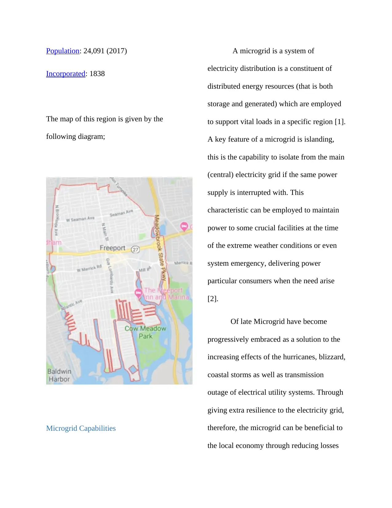
The map of this region is given by the
following diagram;
Microgrid Capabilities
A microgrid is a system of
electricity distribution is a constituent of
distributed energy resources (that is both
storage and generated) which are employed
to support vital loads in a specific region [1].
A key feature of a microgrid is islanding,
this is the capability to isolate from the main
(central) electricity grid if the same power
supply is interrupted with. This
characteristic can be employed to maintain
power to some crucial facilities at the time
of the extreme weather conditions or even
system emergency, delivering power
particular consumers when the need arise
[2].
Of late Microgrid have become
progressively embraced as a solution to the
increasing effects of the hurricanes, blizzard,
coastal storms as well as transmission
outage of electrical utility systems. Through
giving extra resilience to the electricity grid,
therefore, the microgrid can be beneficial to
the local economy through reducing losses
Paraphrase This Document
Need a fresh take? Get an instant paraphrase of this document with our AI Paraphraser

which may occur due to a power outage as
well as attracting new businessmen who are
interested in reliable clean and cost-effective
energy systems [3].
Minimum Required Capabilities
The suggested Freeport Downtown
Microgrid is described by some attributes
that for sure meet the minimum required
capability in the development of this
microgrid. These are described below.
a. Serves at least one but preferably
more, physically separated critical
facilities located on one or more
properties.
The suggested microgrid will provide
43 basic and priority facilities in and around
downtown Freeport (Table 2). Of these
facilities, 19 are seen as basic and are found
in physically isolated buildings on person
property bundles. Basic facilities incorporate
fire stations, the police base camp,
water/wastewater utilities, clinics and
nursing homes, schools, libraries and a crisis
protect. Need offices incorporate extra
utilities, banks, gas stations, basic supply
stores and drug stores [4].
b. The primary generation source
capacity cannot be totally diesel-
fueled generators.
The primary generation source of
electricity for the suggested microgrid
constitutes a combination of the distillate
fuel generator (these are augmented by
battery storage), solar photovoltaic systems,
and neutral gas generators [5]. To add to
these, wind turbines are assessed as an
external power source suggested in this
research paper. In table 3 below are
generation source and their locations. The
diagrams below, figure and figure five
illustrates a map of generation and
generation type respectively. Solar
photovoltaic (PV) frameworks will
incorporate both rooftop installations and
canopies found in metropolitan parking
parts. The venture anticipates extra PV
frameworks present in the Village of
Freeport Schools through the NYPA K-
Solar program [6]. It is expected that the
Sun Edison backed project will give an extra
1 MW of solar. Wind energy will be
provided by at least a single turbine found
within the Freeport Industrial Park. An extra
two 4.44 MW natural gas reciprocating
engines will be found at Freeport Power
Plant 1 (“PP1”). The repowering of PP1
would contribute a noteworthy amount of
power to the proposed microgrid project.
c. A combination of generation
resources must provide on-site
power in both grid-connected and
islanded mode
Joint, the suggested generation
resources would be able to supply on-site
power in both islanded and grid-connected
mode and frame a deliberateness island [7].
The existing PP2, as well as the repowered
PP1, are dark begin capably, and battery
storage and inverters will be utilized to
supply islanded power support through top
shaving and generator start-up period
support. Control frameworks for exchanging
between islanded and grid-connected mode
will be created so that, within the occasion
of a power loss, the proposed microgrid is
able to naturally isolated from the network
and reestablish a network connection after
ordinary power is restored. It is envisioned
that a system like those given by S&C and
Schneider might be utilized for this project
[8].
d. Must be able to form an
intentional island.
⊘ This is a preview!⊘
Do you want full access?
Subscribe today to unlock all pages.

Trusted by 1+ million students worldwide
Freeport Electric will have to control
the microgrid and control the person circuits
and feeders. The Freeport Downtown
Microgrid will have the capacity to island
and partitioned from the LIPA network as
well as other ranges of Freeport.
e. Power Flexibility
The power generated from this
Microgrid will be very flexible as it will
be produced from various sectors like
wind, solar PV, hydroelectric power
plant. Therefore if one plant is affected
by weather then the other will generate
electrical energy will enable continuity
of electrical power source.
f. -scheduled maintenance
The suggested resources will be
planned for firm capacity support; irregular
resources would be utilized to shave peak
loads and progress generally the system
variable costs where conceivable [9].
Freeport Electric staff will keep up the
distribution lines and components. Freeport
Electric may keep up the production
resources but it is, however, to be decided
who would be the owner/operator of these
sources.
g. Consistent Operation
The expecting control framework
and production resources will give load
following capabilities whereas keeping up
voltage and frequency when grid-connected,
and inside ANSI c84-1 guidelines for
voltage when islanded. Reciprocating units
like the one aiming to repower PP1 are
ordinarily able of this performance [10].
h. Control and Communication
A way of computerized, integrated
two-way communication and control
between the suggested microgrid
owner/operator and the neighbourhood
distribution utility is right now under
improvement [11]. The neighbourhood
utility, the metropolitan electric authority of
Paraphrase This Document
Need a fresh take? Get an instant paraphrase of this document with our AI Paraphraser

Freeport Electric, would too specifically
control the microgrid resources.
i. Diverse Customers
The suggested microgrid will supply
power to a several bunches of clients with an
extent of load condition constituting the
basic and essential facilities given above that
are in the proposed microgrid zone, some
245 clients (characterized as person bundles
and excluding parking areas, right of ways
and empty lands) will be served specifically
and indirectly by the Freeport Downtown
Microgrid. Of these bundles, roughly 54%
are commercial, 35% are residential and
10% are community services (Table 1).
Table 1: Microgrid area customer types
Microgrid
Area Land
Use
Parcel
Count
Per cent
Total
Commercial 133 54.3
Residential 86 35.1
Community
Services
26 10. 6
Grand Total 245 100
j. Must include an uninterruptible
fuel supply or a minimum of one
week of fuel supply onsite
PP1 will be repowered as a natural
gas treating facility and give an
uninterruptible fuel supply. PP1 will be
advantageous from critical residual gas
supply within the nearby pipeline and also
utilize of liquefied natural gas (LNG) as a
conveyed fuel [12]. PP1 will moreover keep
an existing distillate fueled generator with
neighbourhood liquid fuel stored on-site.
Propane alternatives are moreover being
examined.
k. critical facilities and generation

This Microgrid in Freeport will be
constructed using facilities to help to
withstand any risks which may pose serious
dangers on the Microgrid plant. Some of
these include the use of tall lightning
arresters which will help in avoiding any
lightning from occurring. Another critical
facility which would be employed is a good
drainage system which would be able to
make water flow into the nearby rivers as
well as lakes to avoid flood in the power
system.
l. Resilient to Disruption
The suggested microgrid will help the region
in and around downtown Freeport that is
located out of the 100-year floodplain and
will not be affected by most ordinary flood
events (Figure 1). Extra resilience in
microgrid arrangement will be given
through measures like undergrounding of
overhead control lines and installation of
extra switching [13].
⊘ This is a preview!⊘
Do you want full access?
Subscribe today to unlock all pages.

Trusted by 1+ million students worldwide

Figure 1: Showing Freeport Downtown
Microgrid and 100 Year Floodplain Map of
Freeport
m. Provide black-start capability
The Downtown Microgrid will have black
start capability utilizing one of the suggested
PP1 4.44 MW engines. PP2, outside the
microgrid, as of now has black start-ability.
This will give the Village with two sources
of control with the black start [14].
Preferable Microgrid Capabilities
In the design of this microgrid in
Freeport, there will be several innovative
technologies which will be employed to
ensure the smooth operation of this
particular microgrid. Some of these
technologies include the human-machine
interface which enables man to safely
Paraphrase This Document
Need a fresh take? Get an instant paraphrase of this document with our AI Paraphraser

interact with the machine. And machine here
is those that directly synchronized to the
microgrid operation in the generation of
electrical energy from renewable sources of
electrical energy [15]. The smart grid
technology which will be employed here
will enable the operator to perfectly monitor
the whole microgrid to check if there is any
fault in the whole system. The smart grid
technology will also help in checking if
there are some mischiefs in electrical energy
line as this may in some cases result in the
death of these people committing mischiefs
of electrical power. Mischiefs may be poor
tapping of electrical energy, poor cabling of
the electrical energy and poor connections of
electrical energy which may result in death
and serious accidents [16].
Here the technologies like smart
meter will as well be employed to help
monitor and record the electrical energy
consumption and then wirelessly transmit
the information to the Freeport microgrid
electrical energy suppliers for billing and
monitoring. These smart meters will record
energy hourly or more frequently and in
some cases even report at least daily [17].
Therefore this type of meter enables
communication in a two way that is between
the central system and the clients (where the
meter is situated). Advance distribution
automaton will also be employed in this
microgrid. This will basically relate
automation distribution which will be
enabled through the smart grid of the
Freeport For this type of technology, the
electrical power is ideally isolated logically
into distribution and transmission systems.
This system is basically achieved by the use
of the Supervisory Control and Data
Acquisition what is most cases referred to as
SCADA.
In the operation of the microgrid,
there needs to be some serious energy
storage this is because the energy storage
and microgrid are very serious issues for
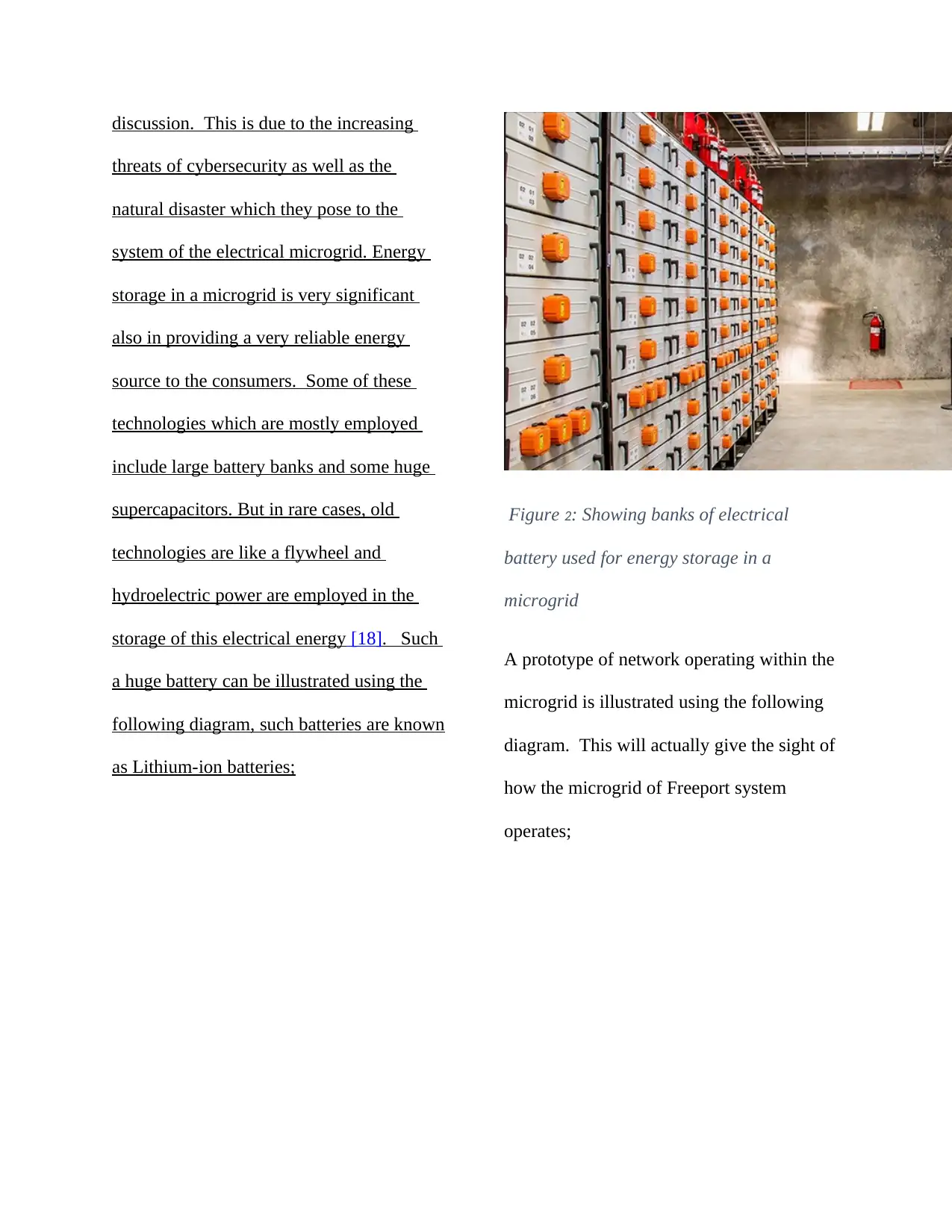
discussion. This is due to the increasing
threats of cybersecurity as well as the
natural disaster which they pose to the
system of the electrical microgrid. Energy
storage in a microgrid is very significant
also in providing a very reliable energy
source to the consumers. Some of these
technologies which are mostly employed
include large battery banks and some huge
supercapacitors. But in rare cases, old
technologies are like a flywheel and
hydroelectric power are employed in the
storage of this electrical energy [18]. Such
a huge battery can be illustrated using the
following diagram, such batteries are known
as Lithium-ion batteries;
Figure 2: Showing banks of electrical
battery used for energy storage in a
microgrid
A prototype of network operating within the
microgrid is illustrated using the following
diagram. This will actually give the sight of
how the microgrid of Freeport system
operates;
⊘ This is a preview!⊘
Do you want full access?
Subscribe today to unlock all pages.

Trusted by 1+ million students worldwide
1 out of 45
Your All-in-One AI-Powered Toolkit for Academic Success.
+13062052269
info@desklib.com
Available 24*7 on WhatsApp / Email
![[object Object]](/_next/static/media/star-bottom.7253800d.svg)
Unlock your academic potential
Copyright © 2020–2025 A2Z Services. All Rights Reserved. Developed and managed by ZUCOL.
