ENS1253 Electrical Engineering 1B: Circuit Design Project Final Report

Verified

Added on  2023/06/03

|5
|581
|187
Report
AI Summary
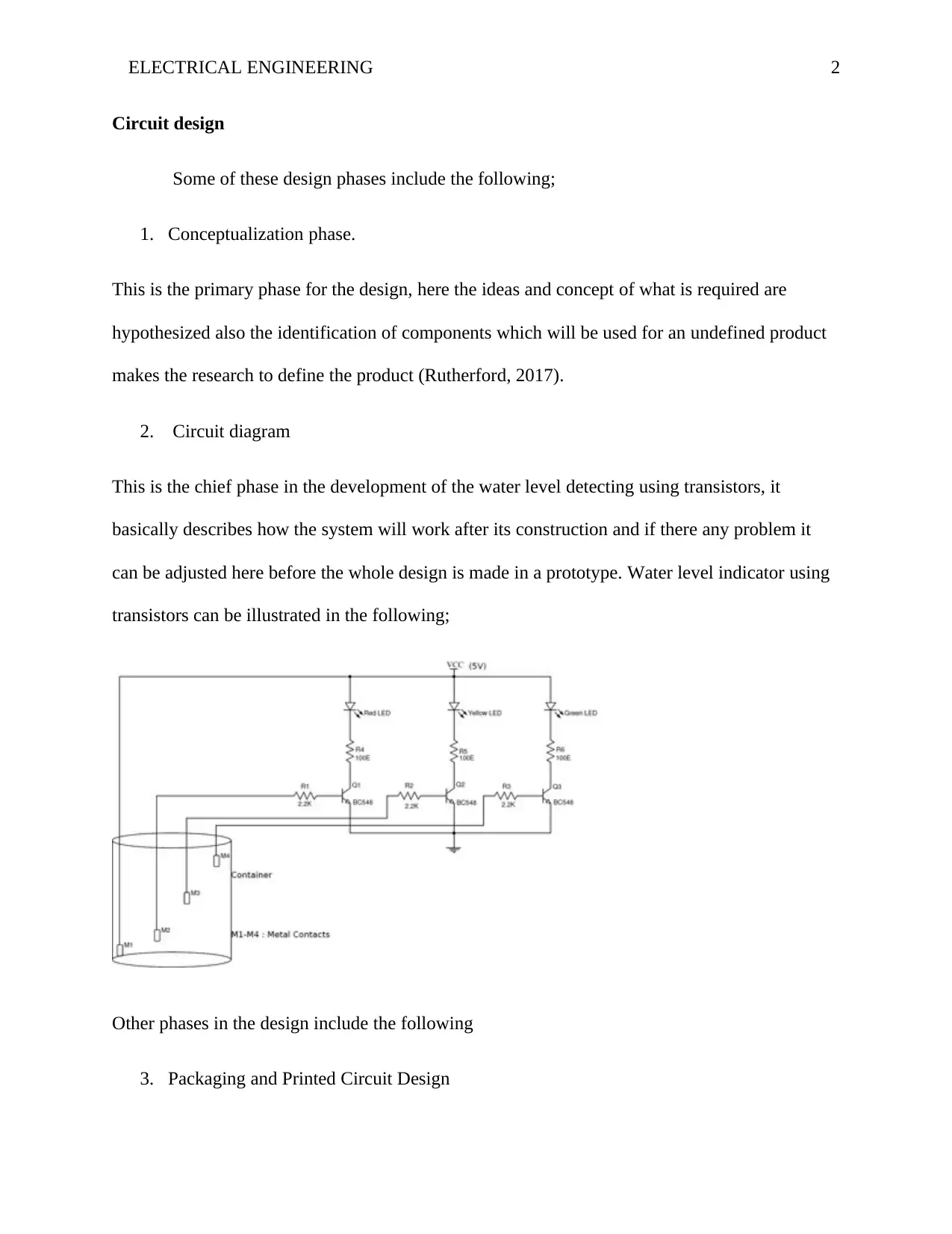
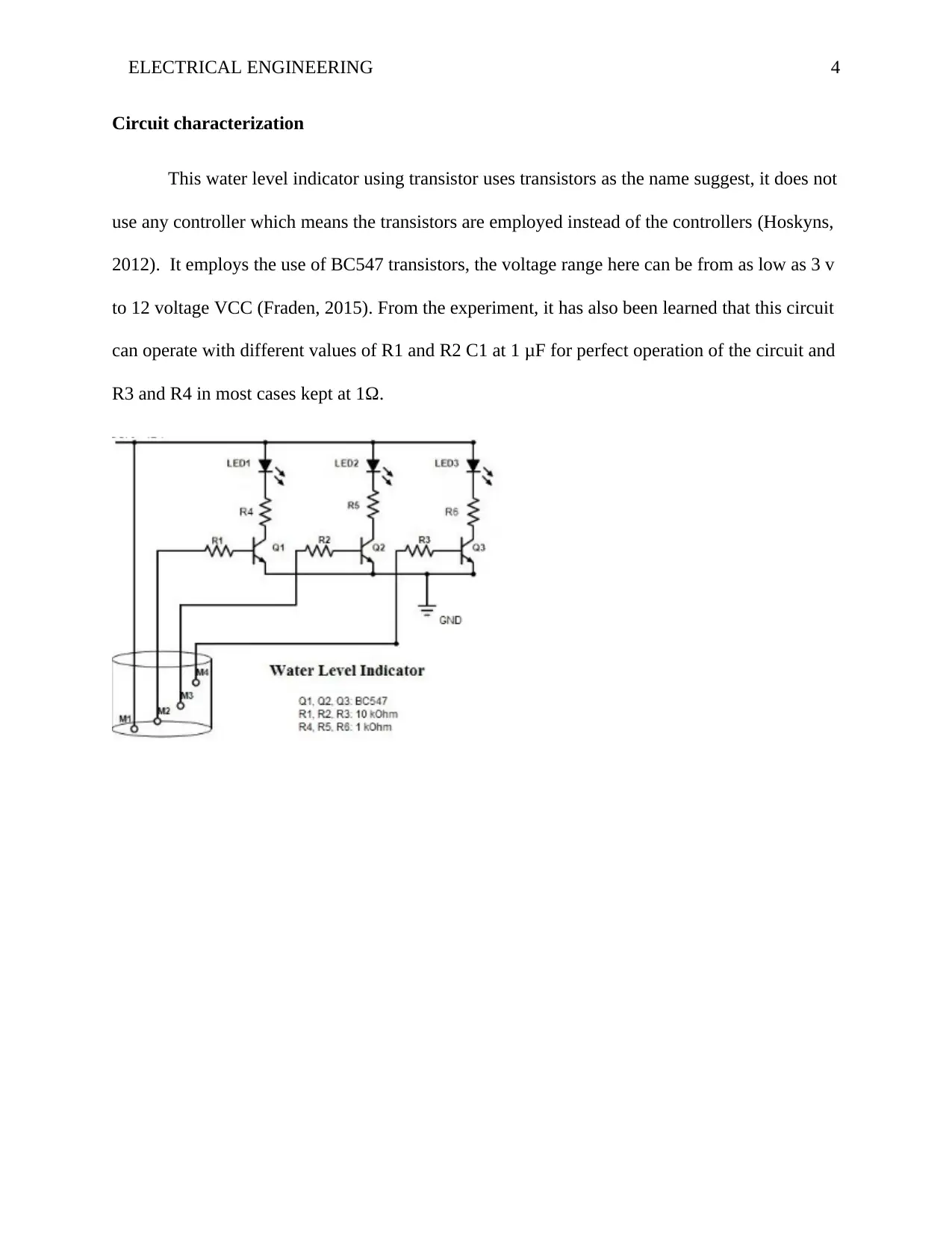
This report presents an electrical engineering circuit design project focused on creating a water level indicator using transistors. The project encompasses several design phases, including conceptualization, circuit diagram development, packaging, production, and testing. The construction phase highlights the use of LEDs as output indicators due to their compatibility with the transistors' voltage and current specifications, and the use of different LED colors to solve the problem of multiple signals. The circuit characterization section details the use of BC547 transistors, voltage ranges, and component values for optimal circuit performance. The report also includes references to relevant literature.
Document Page
Running head: ELECTRICAL ENGINEERING 0
ELECTRICAL ENGINEERING
Name of Student
Institution Affiliation
tabler-icon-diamond-filled.svg

Paraphrase This Document

Need a fresh take? Get an instant paraphrase of this document with our AI Paraphraser
Document Page
ELECTRICAL ENGINEERING 2
Circuit design
Some of these design phases include the following;
1. Conceptualization phase.
This is the primary phase for the design, here the ideas and concept of what is required are
hypothesized also the identification of components which will be used for an undefined product
makes the research to define the product (Rutherford, 2017).
2. Circuit diagram
This is the chief phase in the development of the water level detecting using transistors, it
basically describes how the system will work after its construction and if there any problem it
can be adjusted here before the whole design is made in a prototype. Water level indicator using
transistors can be illustrated in the following;
Other phases in the design include the following
3. Packaging and Printed Circuit Design
Document Page
ELECTRICAL ENGINEERING 3
4. Production and testing
Circuit construction
During the construction of this project, it was realized that it is only LED which could
operate perfectly with the transistors used instead of controller. Therefore it for this construction
where transistors are employed hence LED was the most preferable (Platt, 2010). This is because
transistors use low voltage and low current which matches the power specifications of the LED.
And with there was a problem with using other forms of displaying output buzzer since there is
three signal which needs to be displayed so it was very difficult to identify which buzzer is
giving the signal (Fraden, 2015). And this problem was later solved using LED of different
colours that are RED, YELLOW and GREEN to help identify the signals displayed. Another
slight problem which was encountered was the connection of the transistor (i.e connecting the
emitter, base and collector) but the issue was solved. This can be illustrated as below;
Document Page
ELECTRICAL ENGINEERING 4
Circuit characterization
This water level indicator using transistor uses transistors as the name suggest, it does not
use any controller which means the transistors are employed instead of the controllers (Hoskyns,
2012). It employs the use of BC547 transistors, the voltage range here can be from as low as 3 v
to 12 voltage VCC (Fraden, 2015). From the experiment, it has also been learned that this circuit
can operate with different values of R1 and R2 C1 at 1 μF for perfect operation of the circuit and
R3 and R4 in most cases kept at 1Ω.
tabler-icon-diamond-filled.svg

Paraphrase This Document

Need a fresh take? Get an instant paraphrase of this document with our AI Paraphraser
Document Page
ELECTRICAL ENGINEERING 5
References
Fraden, J. (2015). Handbook of Modern Sensors: Physics, Designs, and Applications (1st ed., Vol. II). Hull:
Springer.
Hoskyns, H. (2012). Basic Electronic Circuits (4th ed., Vol. II). Hull: Springer Science & Business Media.
Platt, C. (2010). Make: Electronics: Learning Through Discovery (2nd ed., Vol. II). Chicago: O'Reilly Media.
Rutherford, J. (2017). The Ultimate Beginner's Guide to the 555 Timer: Build the Atari Punk Console and
Other Breadboard Electronics Projects (5th ed., Vol. I). Chicago: Independently Published.
chevron_up_icon
1 out of 5
circle_padding
hide_on_mobile
zoom_out_icon
[object Object]