EE-362 Project Report: Power System Analysis of an 11-Bus System
VerifiedAdded on 2022/10/14
|14
|2216
|16
Project
AI Summary
This project presents a comprehensive power system analysis of an 11-bus system using ETAP software. It begins with an explanation of power flow, highlighting voltage drops and transmission line losses. The project addresses an overload problem created in the system, resolving it through methods like converting to bundled conductors and adding parallel conductors. Furthermore, it includes a fault analysis, simulating three-phase and line-to-ground faults, and analyzes phase and sequence currents. Finally, the project tackles a low power factor issue, rectifying it using capacitor banks and synchronous condensers. The analysis provides insights into practical solutions for power system challenges, demonstrating the application of ETAP tools for power system design and optimization. Desklib offers similar solved assignments and resources for students.

CEP PROJECT
Power System Analysis
COURSE CODE: EE-362
GROUP MEMBERS:
Electrical Engineering Department
Batch (2017-2018)
Name Roll No.
Ayesha Muddassir Rizvi EE-17086
Syeda Ariba Shahid EE-17089
Power System Analysis
COURSE CODE: EE-362
GROUP MEMBERS:
Electrical Engineering Department
Batch (2017-2018)
Name Roll No.
Ayesha Muddassir Rizvi EE-17086
Syeda Ariba Shahid EE-17089
Paraphrase This Document
Need a fresh take? Get an instant paraphrase of this document with our AI Paraphraser
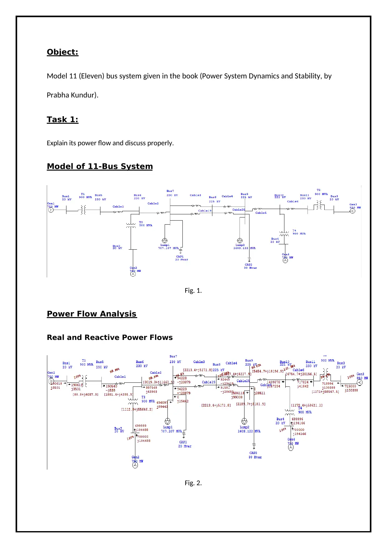
Object:
Model 11 (Eleven) bus system given in the book (Power System Dynamics and Stability, by
Prabha Kundur).
Task 1:
Explain its power flow and discuss properly.
Model of 11-Bus System
Fig. 1.
Power Flow Analysis
Real and Reactive Power Flows
Fig. 2.
Model 11 (Eleven) bus system given in the book (Power System Dynamics and Stability, by
Prabha Kundur).
Task 1:
Explain its power flow and discuss properly.
Model of 11-Bus System
Fig. 1.
Power Flow Analysis
Real and Reactive Power Flows
Fig. 2.
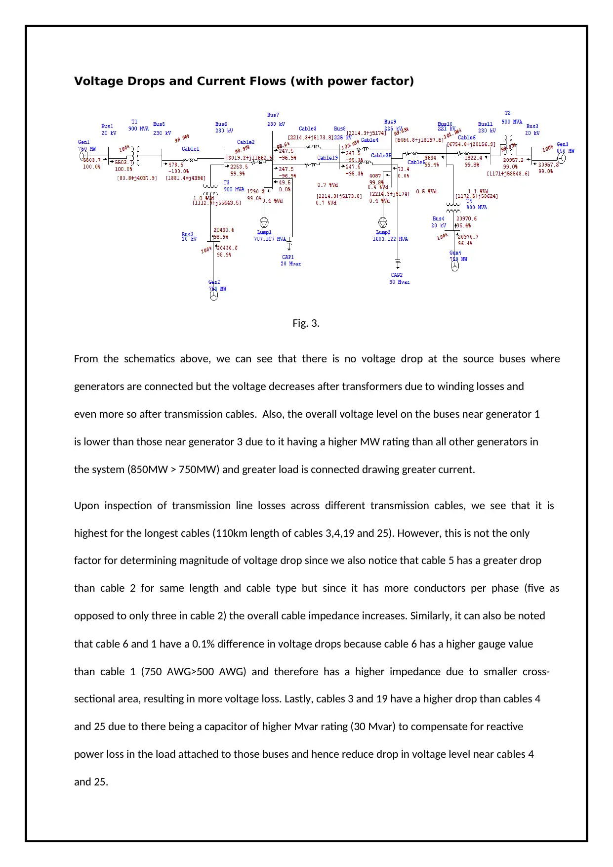
Voltage Drops and Current Flows (with power factor)
Fig. 3.
From the schematics above, we can see that there is no voltage drop at the source buses where
generators are connected but the voltage decreases after transformers due to winding losses and
even more so after transmission cables. Also, the overall voltage level on the buses near generator 1
is lower than those near generator 3 due to it having a higher MW rating than all other generators in
the system (850MW > 750MW) and greater load is connected drawing greater current.
Upon inspection of transmission line losses across different transmission cables, we see that it is
highest for the longest cables (110km length of cables 3,4,19 and 25). However, this is not the only
factor for determining magnitude of voltage drop since we also notice that cable 5 has a greater drop
than cable 2 for same length and cable type but since it has more conductors per phase (five as
opposed to only three in cable 2) the overall cable impedance increases. Similarly, it can also be noted
that cable 6 and 1 have a 0.1% difference in voltage drops because cable 6 has a higher gauge value
than cable 1 (750 AWG>500 AWG) and therefore has a higher impedance due to smaller cross-
sectional area, resulting in more voltage loss. Lastly, cables 3 and 19 have a higher drop than cables 4
and 25 due to there being a capacitor of higher Mvar rating (30 Mvar) to compensate for reactive
power loss in the load attached to those buses and hence reduce drop in voltage level near cables 4
and 25.
⊘ This is a preview!⊘
Do you want full access?
Subscribe today to unlock all pages.
Trusted by 1+ million students worldwide

Generator 1 is the only swing generator in the system and has property to accommodate all system
power losses since the bus it is connected to can be modeled as an infinite source of power
theoretically but practically it has some limits. The remaining three generators are voltage controlled
and can therefore control voltage magnitude of the system with the expense of a change in reactive
power supplied.
When modeling the system, it was evident that cable 2 and 5 were heavily overloaded due to there
being generators connected to both the buses of these cables (Bus 6 and Bus 10). The additional power
entering from the nearby generators at either end of the line and the directly connected ones resulted
in a huge surge of power at both these points (due to summing up). This caused a much higher power
flow and hence greater current flow across these cables above their rated current limit. To resolve the
problem, we had to use bundled conductors of three and five conductors per phase to increase the
cables’ current carrying capacity.
Task 2:
Create overload problem at any portion of the 11-bus system and solve it by at least two appropriate
methods.
Overload Rectification Methods
Below are explained five possible solutions for rectification of overload condition created in the 11-
bus system. We have implemented two of those solutions and attached screenshots from the working
model. The solutions applied to the system were executed on Cable 5, running between bus 9 and 10,
by first converting it into a bundled conductor and then adding a separate conductor parallel to it of
same length and specifications. Therefore, we have only applied the first two solutions to our model
but explained other possible solutions theoretically as well.
Paraphrase This Document
Need a fresh take? Get an instant paraphrase of this document with our AI Paraphraser
A) Convert from Single Conductor to Bundle Conductors (Solution 1)
In this case, we are converting the most heavy loaded transmission line and the lines which are near
to heavy loads to bundled conductors (two or more wires per phase) until the overloading problem is
resolved.
B) Convert from Single Conductor to Parallel Conductors (Solution 2)
Here, the second solution will be applied, which is converting the most heavy loaded transmission line,
similar to the case as bundled conductor overload situation, into parallel transmission line instead of
bundled conductor above.
C) Parallel Generator with Parallel Transmission Line (Solution 3)
The third solution is adding parallel steam turbine generators to the main generators with same
specification of transformers connected with timer circuit breakers. In this solution, at the beginning,
we proposed that it will have only two parallel generators working synchronically. Adding parallel
generators was not enough to eliminate the overload problem due to increase in the supply of active
and reactive power and the inability of the transmission line to carry the new changes in the
generators so some of these transmission lines will have to be changed into parallel transmission lines.
D) Adding Distribution Generator (Solution 4)
In this case, the fourth solution will be applied, which is adding three distribution diesel generators to
the overload circuit connected with timer circuit breakers as piecemeal (one by one with different
time). The places of the distribution generators are chosen beside the most loaded part in the circuit.
E) Adding parallel Transformer (Solution 5)
In this case we will be adding parallel transformer to the loads, where these transformers have the
same specification working synchronically.
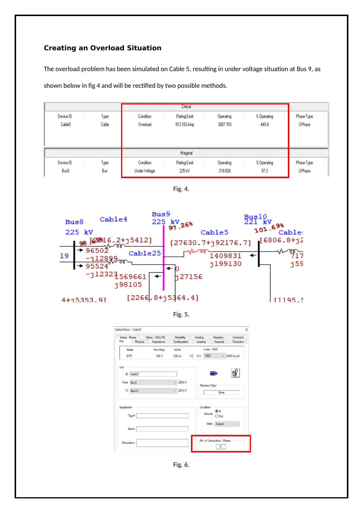
Creating an Overload Situation
The overload problem has been simulated on Cable 5, resulting in under voltage situation at Bus 9, as
shown below in fig 4 and will be rectified by two possible methods.
Fig. 4.
Fig. 5.
Fig. 6.
The overload problem has been simulated on Cable 5, resulting in under voltage situation at Bus 9, as
shown below in fig 4 and will be rectified by two possible methods.
Fig. 4.
Fig. 5.
Fig. 6.
⊘ This is a preview!⊘
Do you want full access?
Subscribe today to unlock all pages.
Trusted by 1+ million students worldwide

Applying solution 1 (Bundled Conductors)
Fig. 7.
The following screenshot in fig 8 is of the Alert View that shows the overload problem has been
rectified by increasing the number of conductors per phase in Cable 5 from one to five.
Fig. 8.
Fig. 7.
The following screenshot in fig 8 is of the Alert View that shows the overload problem has been
rectified by increasing the number of conductors per phase in Cable 5 from one to five.
Fig. 8.
Paraphrase This Document
Need a fresh take? Get an instant paraphrase of this document with our AI Paraphraser
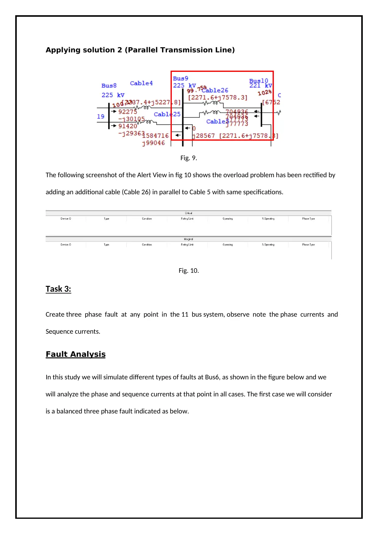
Applying solution 2 (Parallel Transmission Line)
Fig. 9.
The following screenshot of the Alert View in fig 10 shows the overload problem has been rectified by
adding an additional cable (Cable 26) in parallel to Cable 5 with same specifications.
Fig. 10.
Task 3:
Create three phase fault at any point in the 11 bus system, observe note the phase currents and
Sequence currents.
Fault Analysis
In this study we will simulate different types of faults at Bus6, as shown in the figure below and we
will analyze the phase and sequence currents at that point in all cases. The first case we will consider
is a balanced three phase fault indicated as below.
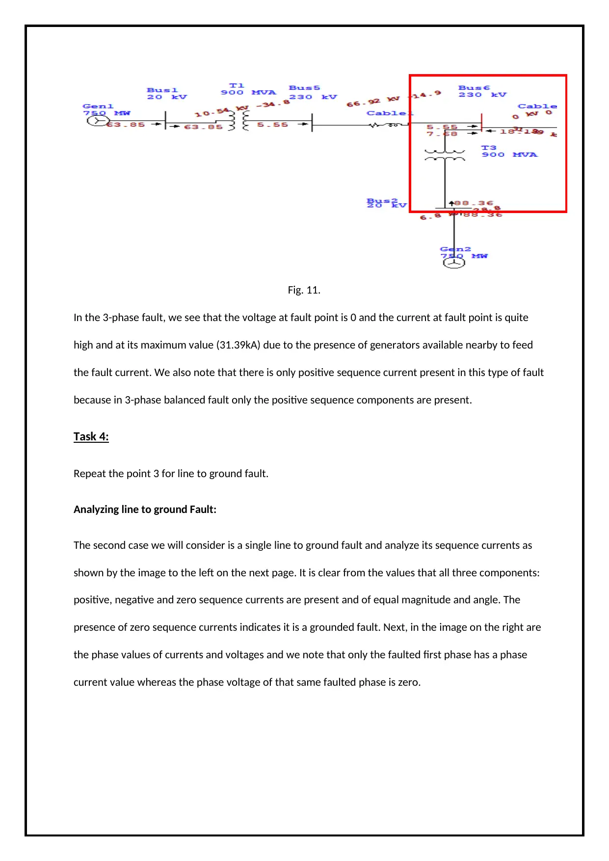
Fig. 11.
In the 3-phase fault, we see that the voltage at fault point is 0 and the current at fault point is quite
high and at its maximum value (31.39kA) due to the presence of generators available nearby to feed
the fault current. We also note that there is only positive sequence current present in this type of fault
because in 3-phase balanced fault only the positive sequence components are present.
Task 4:
Repeat the point 3 for line to ground fault.
Analyzing line to ground Fault:
The second case we will consider is a single line to ground fault and analyze its sequence currents as
shown by the image to the left on the next page. It is clear from the values that all three components:
positive, negative and zero sequence currents are present and of equal magnitude and angle. The
presence of zero sequence currents indicates it is a grounded fault. Next, in the image on the right are
the phase values of currents and voltages and we note that only the faulted first phase has a phase
current value whereas the phase voltage of that same faulted phase is zero.
⊘ This is a preview!⊘
Do you want full access?
Subscribe today to unlock all pages.
Trusted by 1+ million students worldwide
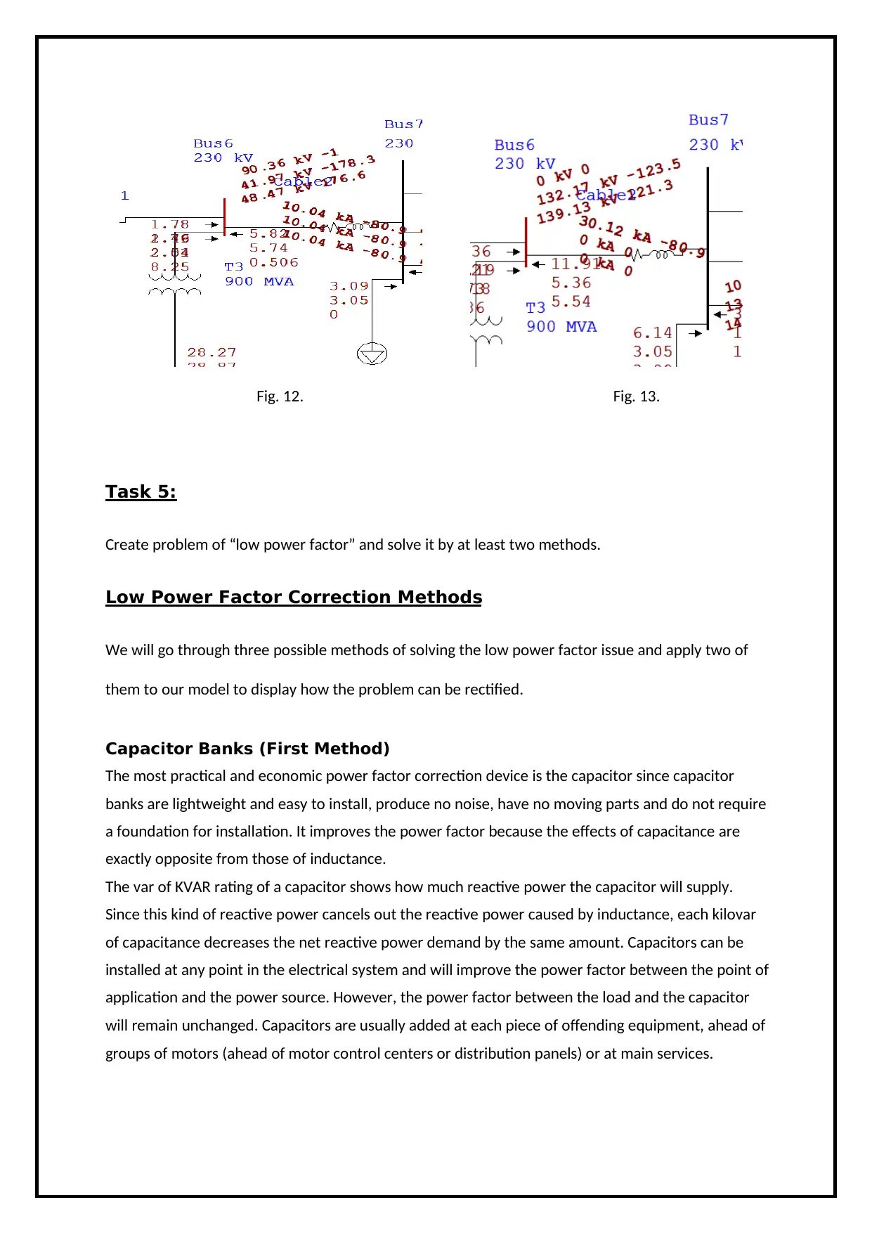
Fig. 12. Fig. 13.
Task 5:
Create problem of “low power factor” and solve it by at least two methods.
Low Power Factor Correction Methods
We will go through three possible methods of solving the low power factor issue and apply two of
them to our model to display how the problem can be rectified.
Capacitor Banks (First Method)
The most practical and economic power factor correction device is the capacitor since capacitor
banks are lightweight and easy to install, produce no noise, have no moving parts and do not require
a foundation for installation. It improves the power factor because the effects of capacitance are
exactly opposite from those of inductance.
The var of KVAR rating of a capacitor shows how much reactive power the capacitor will supply.
Since this kind of reactive power cancels out the reactive power caused by inductance, each kilovar
of capacitance decreases the net reactive power demand by the same amount. Capacitors can be
installed at any point in the electrical system and will improve the power factor between the point of
application and the power source. However, the power factor between the load and the capacitor
will remain unchanged. Capacitors are usually added at each piece of offending equipment, ahead of
groups of motors (ahead of motor control centers or distribution panels) or at main services.
Paraphrase This Document
Need a fresh take? Get an instant paraphrase of this document with our AI Paraphraser

Synchronous Condenser (Second Method)
When a synchronous motor operates at no-load and over-exited then it’s called a synchronous
condenser. Whenever a synchronous motor is over-exited then it provides leading current and works
like a capacitor. When a synchronous condenser is connected across supply voltage (in parallel) then
it draws leading current and partially eliminates the re-active component and this way, power factor
is improved. Generally, synchronous condenser is used to improve the power factor in large industries
since they are more expensive to install and maintain along with the requirement of an auxiliary device
to provide the starting torque for its operation.
Phase Advancer (Third Method)
Phase advancer is a simple AC exciter which is connected on the main shaft of the motor and operates
with the motor’s rotor circuit for power factor improvement. Phase advancer is used to improve the
power factor of induction motor in industries. As the stator windings of induction motor takes lagging
current 90° out of phase with Voltage, therefore the power factor of induction motor is low. If the
exciting ampere-turns are excited by external AC source, then there would be no effect of exciting
current on stator windings. Therefore the power factor of induction motor will be improved. This
process is done by Phase advancer. Pase advancers can be used where installing synchronous motors
is not possible, however, they are not economical for motors below 200 HP.
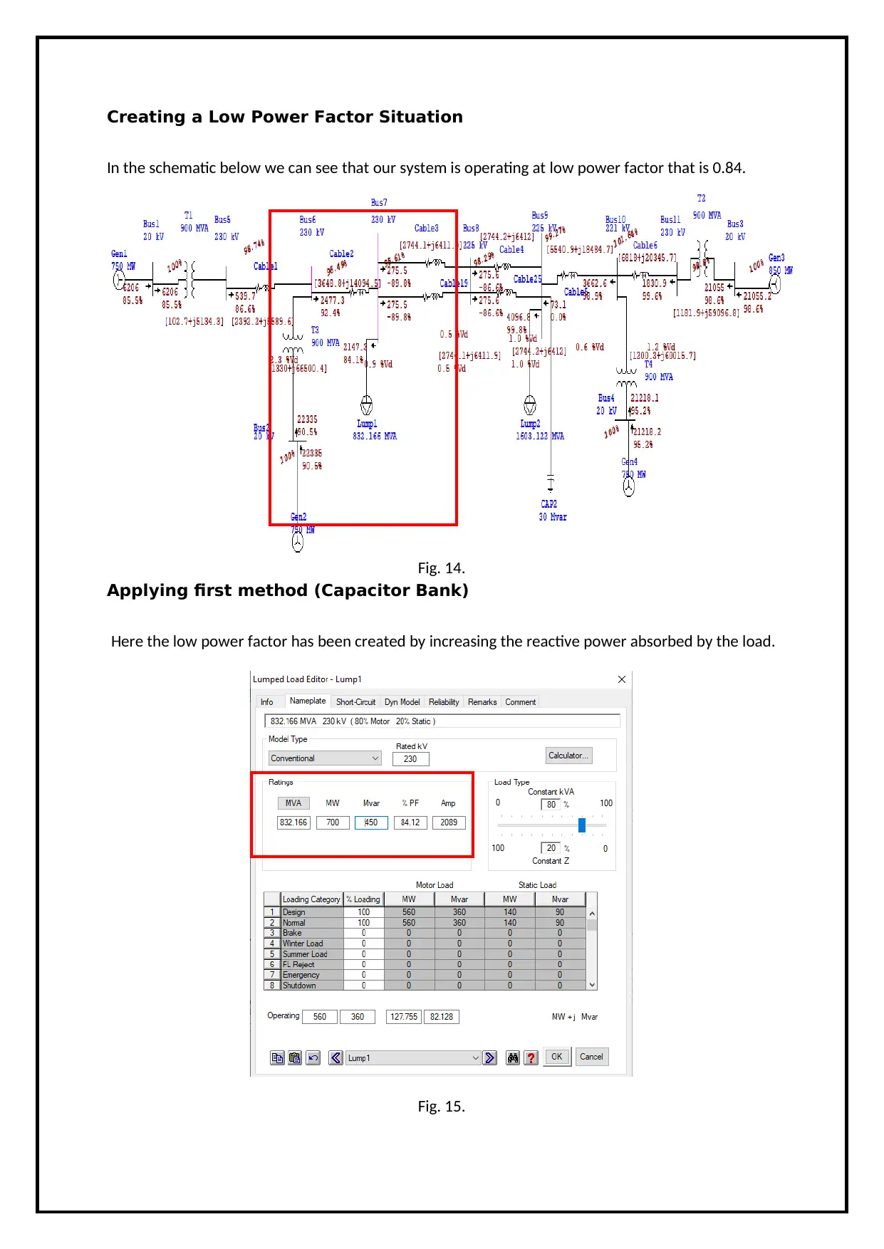
Creating a Low Power Factor Situation
In the schematic below we can see that our system is operating at low power factor that is 0.84.
Fig. 14.
Applying first method (Capacitor Bank)
Here the low power factor has been created by increasing the reactive power absorbed by the load.
Fig. 15.
In the schematic below we can see that our system is operating at low power factor that is 0.84.
Fig. 14.
Applying first method (Capacitor Bank)
Here the low power factor has been created by increasing the reactive power absorbed by the load.
Fig. 15.
⊘ This is a preview!⊘
Do you want full access?
Subscribe today to unlock all pages.
Trusted by 1+ million students worldwide
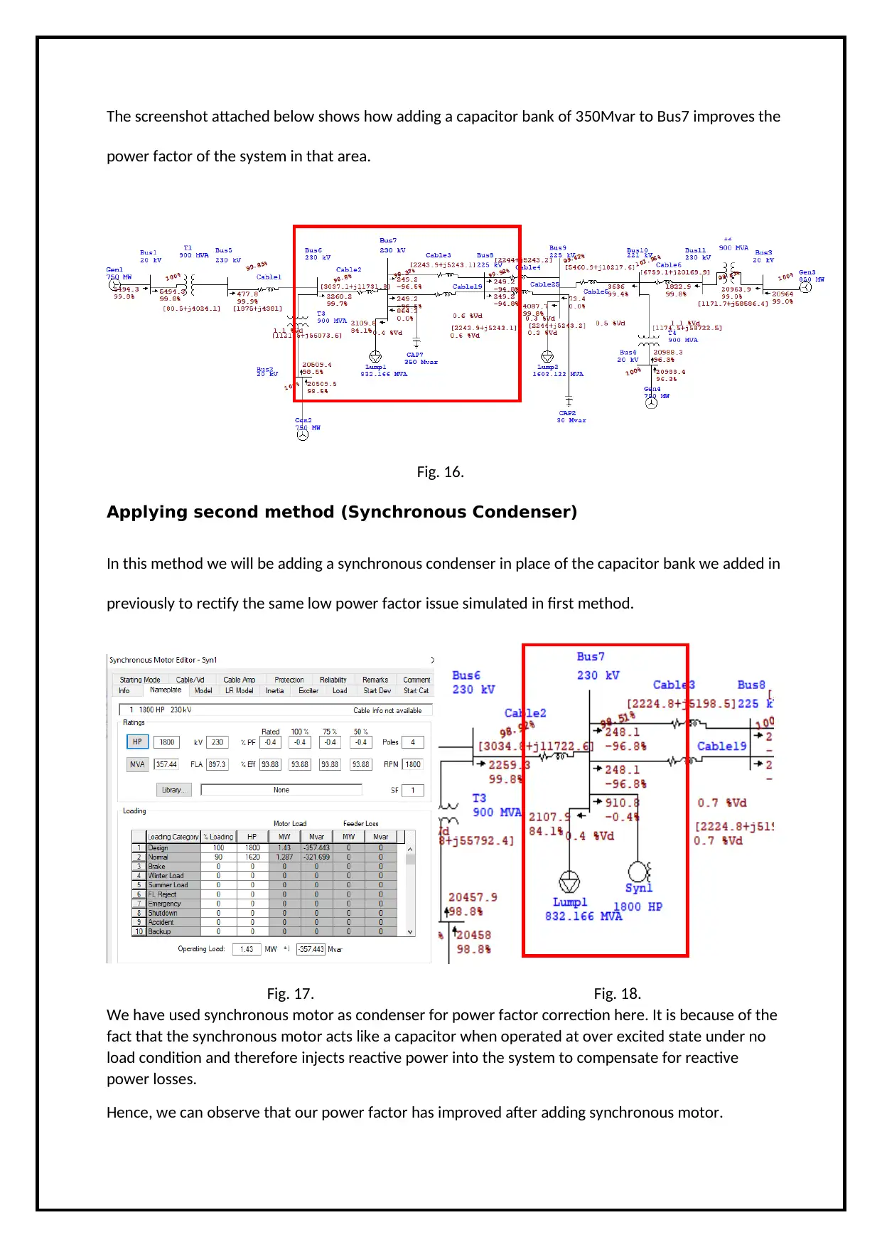
The screenshot attached below shows how adding a capacitor bank of 350Mvar to Bus7 improves the
power factor of the system in that area.
Fig. 16.
Applying second method (Synchronous Condenser)
In this method we will be adding a synchronous condenser in place of the capacitor bank we added in
previously to rectify the same low power factor issue simulated in first method.
Fig. 17. Fig. 18.
We have used synchronous motor as condenser for power factor correction here. It is because of the
fact that the synchronous motor acts like a capacitor when operated at over excited state under no
load condition and therefore injects reactive power into the system to compensate for reactive
power losses.
Hence, we can observe that our power factor has improved after adding synchronous motor.
Paraphrase This Document
Need a fresh take? Get an instant paraphrase of this document with our AI Paraphraser

End Note:
Hence, in this project we have learned to use the ETAP software and applied the tools of ETAP
software for power flow analysis and fault analysis of the 11-bus system. Furthermore, we found
solutions for overload and power factor correction cases.
Hence, in this project we have learned to use the ETAP software and applied the tools of ETAP
software for power flow analysis and fault analysis of the 11-bus system. Furthermore, we found
solutions for overload and power factor correction cases.
1 out of 14


Your All-in-One AI-Powered Toolkit for Academic Success.
+13062052269
info@desklib.com
Available 24*7 on WhatsApp / Email
![[object Object]](/_next/static/media/star-bottom.7253800d.svg)
Unlock your academic potential
© 2024 | Zucol Services PVT LTD | All rights reserved.