Solved Electrical Engineering Problems: USQ Assignment 1 Questions
VerifiedAdded on 2023/06/18
|13
|2494
|461
Homework Assignment
AI Summary
This document presents solutions to a set of electrical engineering questions, likely part of an assignment. The problems cover a range of topics including power factor calculation in power electronics devices, three-winding transformers, RMS value calculations for different waveforms (pulse, trapezoidal), circuit analysis with resistors and capacitors, freewheeling diodes, BJT switching power loss, half-bridge drivers, buck converter design, duty cycle calculations for buck and buck-boost converters, ripple voltage calculation, and analysis of full-bridge DC converters. Each question is accompanied by a detailed solution with formulas and calculations, providing a comprehensive guide to understanding the concepts and problem-solving techniques in electrical engineering. Desklib offers more resources like this to aid students in their studies.
Electrical Engineering
Questions
Questions
Paraphrase This Document
Need a fresh take? Get an instant paraphrase of this document with our AI Paraphraser
Table of Contents
Q.1................................................................................................................................................3
Q.2................................................................................................................................................3
Q.3................................................................................................................................................4
Q.4................................................................................................................................................5
Q.5................................................................................................................................................5
Q.6................................................................................................................................................6
Q.7................................................................................................................................................6
Q.8................................................................................................................................................7
Q.9................................................................................................................................................7
Q.10..............................................................................................................................................8
Q.11 .............................................................................................................................................8
Q.12..............................................................................................................................................9
Q.13..............................................................................................................................................9
Q.14............................................................................................................................................10
Q.15............................................................................................................................................10
REFERENCES..............................................................................................................................12
Q.1
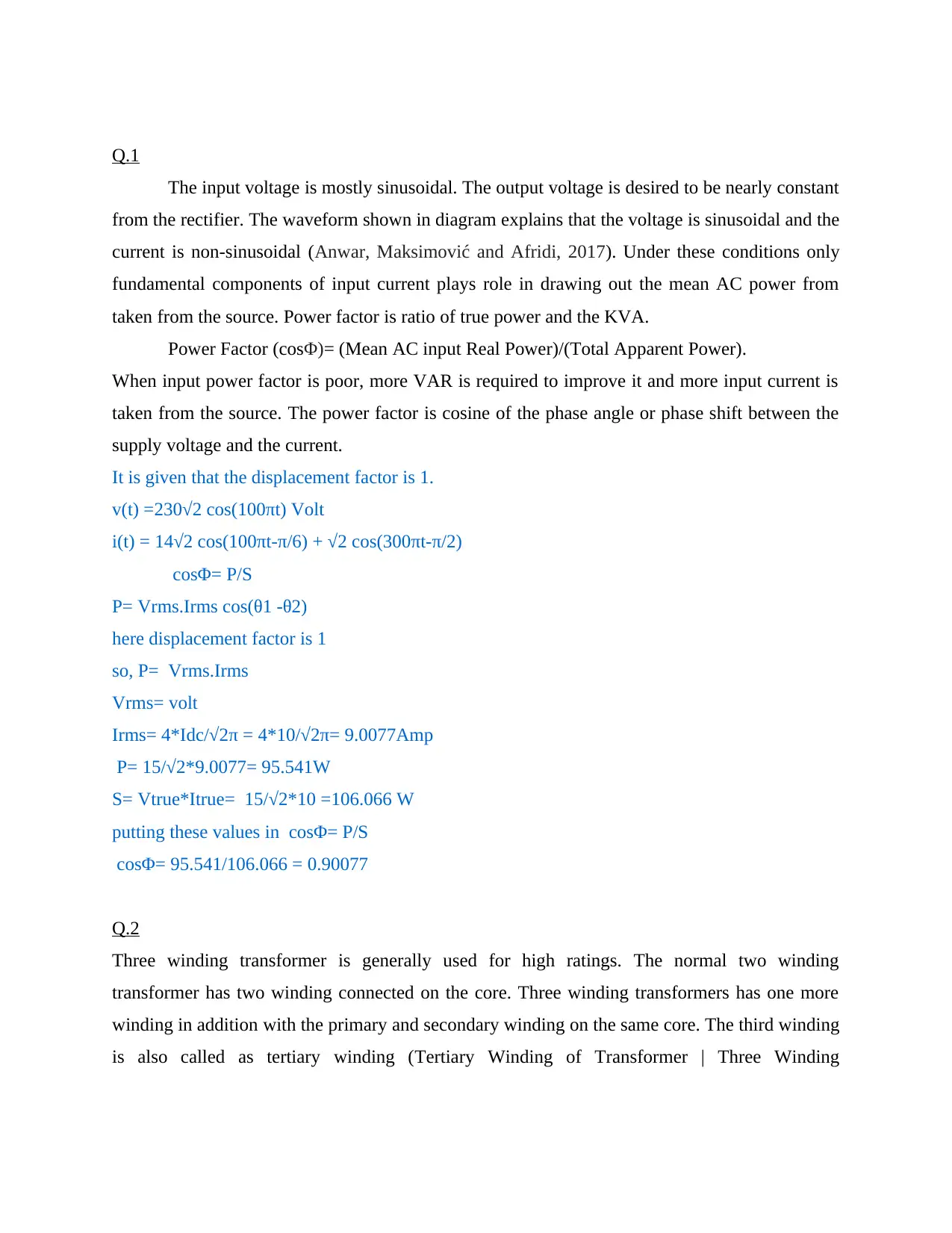
The input voltage is mostly sinusoidal. The output voltage is desired to be nearly constant
from the rectifier. The waveform shown in diagram explains that the voltage is sinusoidal and the
current is non-sinusoidal (Anwar, Maksimović and Afridi, 2017). Under these conditions only
fundamental components of input current plays role in drawing out the mean AC power from
taken from the source. Power factor is ratio of true power and the KVA.
Power Factor (cosΦ)= (Mean AC input Real Power)/(Total Apparent Power).
When input power factor is poor, more VAR is required to improve it and more input current is
taken from the source. The power factor is cosine of the phase angle or phase shift between the
supply voltage and the current.
It is given that the displacement factor is 1.
v(t) =230√2 cos(100πt) Volt
i(t) = 14√2 cos(100πt-π/6) + √2 cos(300πt-π/2)
cosΦ= P/S
P= Vrms.Irms cos(θ1 -θ2)
here displacement factor is 1
so, P= Vrms.Irms
Vrms= volt
Irms= 4*Idc/√2π = 4*10/√2π= 9.0077Amp
P= 15/√2*9.0077= 95.541W
S= Vtrue*Itrue= 15/√2*10 =106.066 W
putting these values in cosΦ= P/S
cosΦ= 95.541/106.066 = 0.90077
Q.2
Three winding transformer is generally used for high ratings. The normal two winding
transformer has two winding connected on the core. Three winding transformers has one more
winding in addition with the primary and secondary winding on the same core. The third winding
is also called as tertiary winding (Tertiary Winding of Transformer | Three Winding
⊘ This is a preview!⊘
Do you want full access?
Subscribe today to unlock all pages.

Trusted by 1+ million students worldwide
Transformer., 2021). The benefit of using the third winding is that it can reduce the unbalancing.
It can be helpful in limiting the current in the times of short circuit conditions.
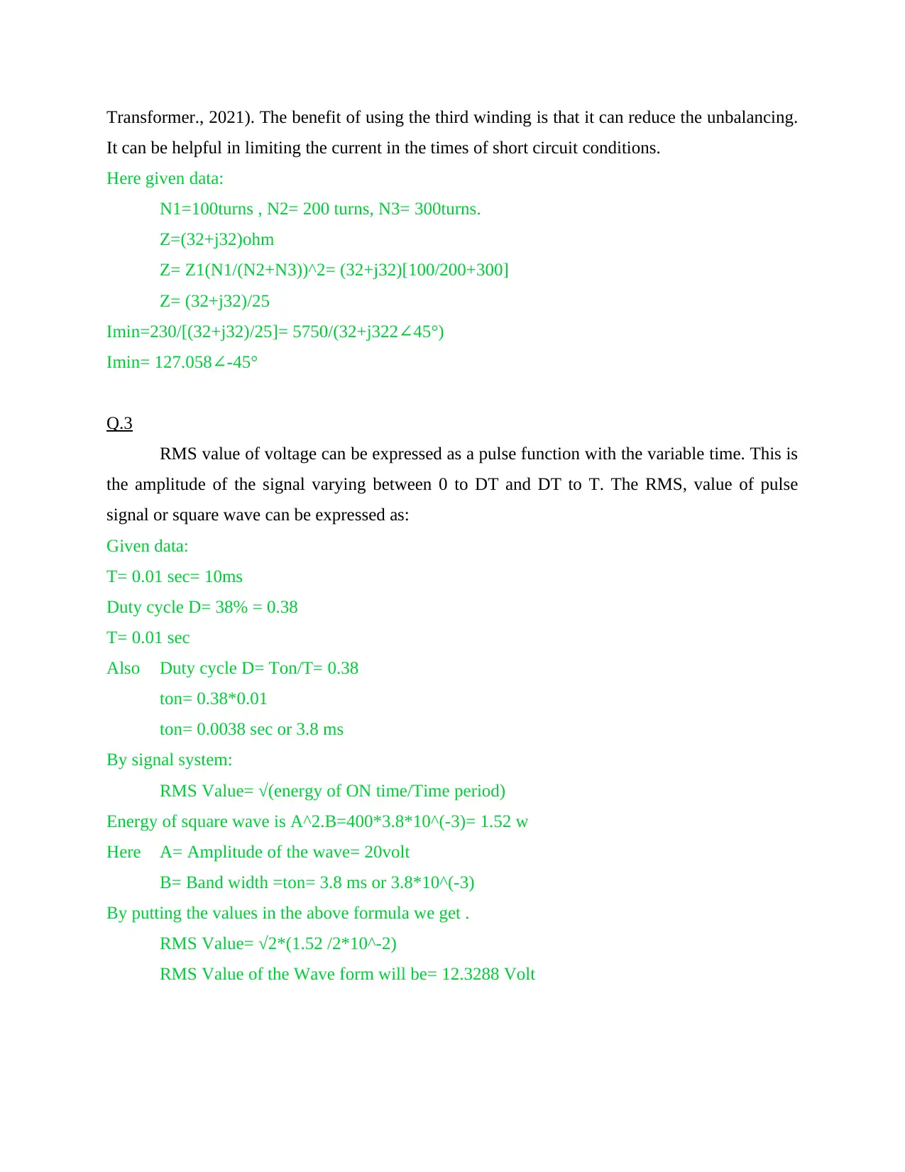
Here given data:
N1=100turns , N2= 200 turns, N3= 300turns.
Z=(32+j32)ohm
Z= Z1(N1/(N2+N3))^2= (32+j32)[100/200+300]
Z= (32+j32)/25
Imin=230/[(32+j32)/25]= 5750/(32+j322 45∠ °)
Imin= 127.058 -45°∠
Q.3
RMS value of voltage can be expressed as a pulse function with the variable time. This is
the amplitude of the signal varying between 0 to DT and DT to T. The RMS, value of pulse
signal or square wave can be expressed as:
Given data:
T= 0.01 sec= 10ms
Duty cycle D= 38% = 0.38
T= 0.01 sec
Also Duty cycle D= Ton/T= 0.38
ton= 0.38*0.01
ton= 0.0038 sec or 3.8 ms
By signal system:
RMS Value= √(energy of ON time/Time period)
Energy of square wave is A^2.B=400*3.8*10^(-3)= 1.52 w
Here A= Amplitude of the wave= 20volt
B= Band width =ton= 3.8 ms or 3.8*10^(-3)
By putting the values in the above formula we get .
RMS Value= √2*(1.52 /2*10^-2)
RMS Value of the Wave form will be= 12.3288 Volt
Paraphrase This Document
Need a fresh take? Get an instant paraphrase of this document with our AI Paraphraser
Q.4
RMS value means the root square value of AC component. RMS refers to time varying
components of the circuit. RMS value is an equivalent DC value that can produce same amount
of power that is produced by the AC for the same time.
For calculating the RMS value of a trapezoidal signal, firstly the signal is divide in the sections
(How to Calculate the RMS Value of an Arbitrary Waveform., 2021). Then according to the area
of the signal or known RMS the calculations take place.
RMS value of the Positive wave form
=Vp*sqrt[1/T{t2-t1+((t3-t2+t1)/3)}]
RMS1 =8*sqrt[1/2{0.6-0.4+((1-0.6+0.4)/3)}] =3.86volt.
The RMS value of the Negative Waveform will be the same:
RMS Value of the negative part of the wave form RMS2= 3.86 Volt
So total RMS Value= √[(RMS1)^2+(RMS2)^2]
= √[(3.86)^2+(3.86)^2]
=√(14.8996+14.8996)
= 5.4589 Volt
Q.5
The diagram shows that the switch at first connects the resistor with the current source after that
the position of the switch is changed and the current source is now connected with the capacitor.
When the current source is connected to the resistor.
V=IR
Here I= 6.5Amp and R= 10ohm
So voltage across the resistor is 65 Volt.
When the switch is set to the capacitor with no initial charge in it.
Then voltage drop across capacitor can be calculated by
V=Ic/C (0.5T)
V= 6.5/(5.4*10^-6)(0.5*2*10^-3)
V=1203 .7 volt
Q.6
To reduce the rate of change of voltage across the inductor. The ideal freewheeling diodes have
the capability to handle sudden voltage spikes. When the switch is closed, the inductor will get
energized. Now, if the switch disconnects the power supply. The inductor will resist the sudden
drop in current (Chen and et.al., 2019). And current will start to flow in reverse direction. When
the switch is ON the diode is in reverse bias and does not conduct but when the switch is turned
OFF the diode now will be forward biased. It allows the inductor current to flow in the loop. The
current in the inductor starts to decrease when the there is interruption in supply and this tends to
the voltage surge. Freewheeling diodes are used to prevent the voltage spikes across the inductor.
Q.7
BJT: BJT stands for bipolar junction transistor. The flow of current in a BJT is because
of both holes and electrons. There are three terminals in the BJT that are known as emitter,
collector and base (Liu and et.al., 2020). The BJT is used in high power and high current
applications. The transistor operates in saturation region and cut-off regions.
Given Data:
V= 127Volt
I= 10 A
ton= 1micro sec
Time Period=T=1/F so T=100 micro sec
The equation of i(t) can be written as:
i(t)-0=[(1-0)/(ton-0)](t-0)
So, i(t)= [1/ton]*t
The equation of v(t) can be written as:
v(t)-v=[(0-v)/(ton-0)](t-0)
v(t)= (-v/ton) *t+V
Switching Power loss (Pt)=Pon+Poff
It is given that Pon and Poff are equal so Pt=2Pon.
For time period of 0 to ton
Pon avg= ∫v(t).i(t)dt= (VI/6)(ton/T)= (127*10/6)(1/100)
P(t)= 2.1166W
⊘ This is a preview!⊘
Do you want full access?
Subscribe today to unlock all pages.

Trusted by 1+ million students worldwide

so total P(t)loss= 2*2.1166= 4.233W
Q.8
Half Bridge Driver: The half bridge driver is used to drive the gates at low impedances
for reducing the conduction losses. Also the switching time is very fast and has very few
switching losses (Kovac and Gladyr, 2019). It drives the N-channel IGBT with independent
input signal.
It is a half- bridge IGBT driver:
Ic = E/R
Here E= 300Volt R= 11ohm
Ic = 300/11= 27.27 Amp
Vo= E-1.7= 300-2.03=297.97 Volt
P= Vo^2/R
P=297.97^2/11= 8071.83 W
Q.9
The buck converter is a step down DC to DC converter. The circuit of a buck converter consists
of DC power supply source, switch, diode, capacitor and inductor. When the switch is OFF the
inductor current flows through diode and capacitor also discharging into the load. Output voltage
can be defined by s witching frequency and the duty cycle. When the switch is turned ON the
supply voltage is applied and current flows through inductor, capacitor and load.
Selection of inductor:
Given data:
Here Vo= 12Volt and Vin=30 Volt
Duty cycle =Vo/Vin= 12/30 =0.4
Minimum value of inductor:
Lmin= (1-D)R/2fs
Here R=10 ohm and fs= 5kHz or 5000Hz.
Lmin= (1-0.4)*10/2*(5*1000)= 0.6*10^-3 or 6*10^-4 Henry
Paraphrase This Document
Need a fresh take? Get an instant paraphrase of this document with our AI Paraphraser
Q.10
The duty cycle is the ratio of ON time (Ton) and total time (T). Also It can be expressed as the
ratio of output voltage and input voltage.
Duty cycle is used by switching regulators, to control voltage and current in the circuit.
The duty cycle of buck converter can be given as:
Duty Cycle= Vx/Vin
Given that Vin= 72 Volt.
Here Vx= Vo+Vr
Given that Vo= 40 Volt
And Vr= IoR
Here Io= 30 Amp and R= 0.2 Ohm.
Vr= 30*0.2= 6Volt
Here Vx= 40+6= 46Volt
And Duty Cycle= 46/72= 0.638
Q.11
The duty cycle of Buck-boost converter can be realised by:
Vout=Vin[D/(1-D)]
From the about equation duty cycle of buck-boost converter is:
D= Vout/(Vin+Vout)
Here from given data:
Vout= 23Volt; Vin= 30Volt
So the duty cycle of Buck-boost converter will be:
D= 23/(30+23)= 0.43 or 43%
For finding the load resistance that separates continuous and discontinuous current mode:
the minimum size of inductor for continuous conduction can be expressed as:
Lmin= [(1-D)^2/2Fs]*R
Here Fs is switching frequency= 5kHz.
Lmin is the minimum inductance responsible for continuous current= 500microH
R is the resistance
500*10^(-6)= [(1-0.43)^2/2*5*106(3)]*R
by solving this we get,
R=15.62ohm.
The load resistance will be of 15.62 ohm that separates the continuous and discontinuous current
mode.
Q.12
For a buck boost converter:
The Peak to peak ripple voltage is:
ΔVout= Vout*D/(R*C*fs)
Here, Vout= Output Voltage= 40V
R= resistance= 10 Ohm
C= capacitance= 1.2 mF
fs= switching frequency= 5 kHz
D is the duty cycle,
For the buck-boost converter,
Vout=Vin[D/(1-D)]
D= Vout/(Vin+Vout)
Here, Vin= Input Voltage= 30 Volt.
D= 40/(30+40)= 0.57 or 57%
Peak to Peak ripple of out voltage will be:
ΔVout= 40*0.57/(10*0.0012*5000)= 0.38 V
The ripple is mostly undesired. It should be as small. Smaller ripple explains that the filtering in
the circuit is effective.
Q.13
For a full-bridge DC converter with Bipolar control;
Vab= Vin(2D1-1)
Here Vab= 37Volt and Vin= 80 Volt
From the above equation:
37= 80(2*D1-1)
D1-1= 0.4625
D1= 0.73125
⊘ This is a preview!⊘
Do you want full access?
Subscribe today to unlock all pages.

Trusted by 1+ million students worldwide
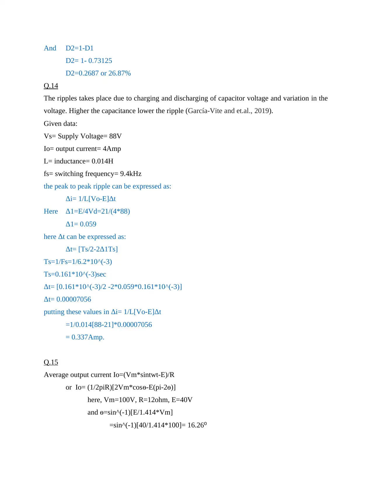
And D2=1-D1
D2= 1- 0.73125
D2=0.2687 or 26.87%
Q.14
The ripples takes place due to charging and discharging of capacitor voltage and variation in the
voltage. Higher the capacitance lower the ripple (García‐Vite and et.al., 2019).
Given data:
Vs= Supply Voltage= 88V
Io= output current= 4Amp
L= inductance= 0.014H
fs= switching frequency= 9.4kHz
the peak to peak ripple can be expressed as:
Δi= 1/L[Vo-E]Δt
Here Δ1=E/4Vd=21/(4*88)
Δ1= 0.059
here Δt can be expressed as:
Δt= [Ts/2-2Δ1Ts]
Ts=1/Fs=1/6.2*10^(-3)
Ts=0.161*10^(-3)sec
Δt= [0.161*10^(-3)/2 -2*0.059*0.161*10^(-3)]
Δt= 0.00007056
putting these values in Δi= 1/L[Vo-E]Δt
=1/0.014[88-21]*0.00007056
= 0.337Amp.
Q.15
Average output current Io=(Vm*sintwt-E)/R
or Io= (1/2piR)[2Vm*cosѳ-E(pi-2ѳ)]
here, Vm=100V, R=12ohm, E=40V
and ѳ=sin^(-1)[E/1.414*Vm]
=sin^(-1)[40/1.414*100]= 16.26⁰
Paraphrase This Document
Need a fresh take? Get an instant paraphrase of this document with our AI Paraphraser

And Io=(1/2*pi*12)[2*100*cos(16.26)-40{pi-(2*16.26*pi)/180}] =2.25 Amp.
Mean value of current= 2Im/pi= 2*2.25/3.14 =1.433 Amp.
Mean value of current= 2Im/pi= 2*2.25/3.14 =1.433 Amp.
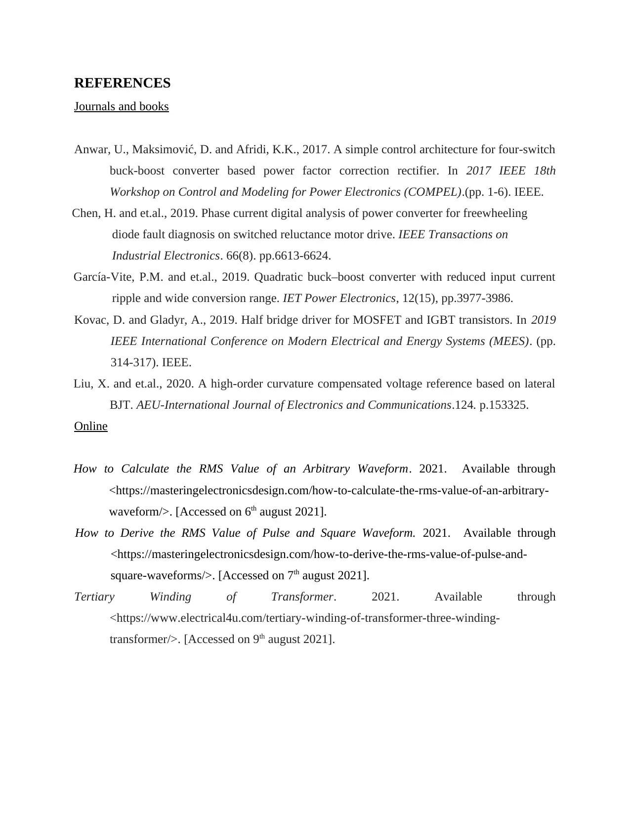
REFERENCES
Journals and books
Anwar, U., Maksimović, D. and Afridi, K.K., 2017. A simple control architecture for four-switch
buck-boost converter based power factor correction rectifier. In 2017 IEEE 18th
Workshop on Control and Modeling for Power Electronics (COMPEL).(pp. 1-6). IEEE.
Chen, H. and et.al., 2019. Phase current digital analysis of power converter for freewheeling
diode fault diagnosis on switched reluctance motor drive. IEEE Transactions on
Industrial Electronics. 66(8). pp.6613-6624.
García‐Vite, P.M. and et.al., 2019. Quadratic buck–boost converter with reduced input current
ripple and wide conversion range. IET Power Electronics, 12(15), pp.3977-3986.
Kovac, D. and Gladyr, A., 2019. Half bridge driver for MOSFET and IGBT transistors. In 2019
IEEE International Conference on Modern Electrical and Energy Systems (MEES). (pp.
314-317). IEEE.
Liu, X. and et.al., 2020. A high-order curvature compensated voltage reference based on lateral
BJT. AEU-International Journal of Electronics and Communications.124. p.153325.
Online
How to Calculate the RMS Value of an Arbitrary Waveform. 2021. Available through
<https://masteringelectronicsdesign.com/how-to-calculate-the-rms-value-of-an-arbitrary-
waveform/>. [Accessed on 6th august 2021].
How to Derive the RMS Value of Pulse and Square Waveform. 2021. Available through
<https://masteringelectronicsdesign.com/how-to-derive-the-rms-value-of-pulse-and-
square-waveforms/>. [Accessed on 7th august 2021].
Tertiary Winding of Transformer. 2021. Available through
<https://www.electrical4u.com/tertiary-winding-of-transformer-three-winding-
transformer/>. [Accessed on 9th august 2021].
⊘ This is a preview!⊘
Do you want full access?
Subscribe today to unlock all pages.

Trusted by 1+ million students worldwide
1 out of 13
Your All-in-One AI-Powered Toolkit for Academic Success.
+13062052269
info@desklib.com
Available 24*7 on WhatsApp / Email
![[object Object]](/_next/static/media/star-bottom.7253800d.svg)
Unlock your academic potential
Copyright © 2020–2025 A2Z Services. All Rights Reserved. Developed and managed by ZUCOL.
