Electrical Power Assignment: Circuit Analysis and Power Factors
VerifiedAdded on 2023/01/18
|10
|494
|40
Homework Assignment
AI Summary
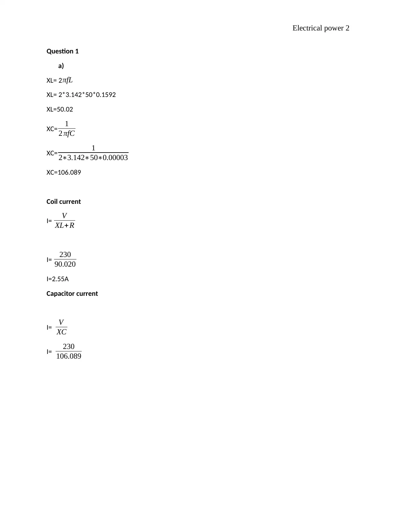
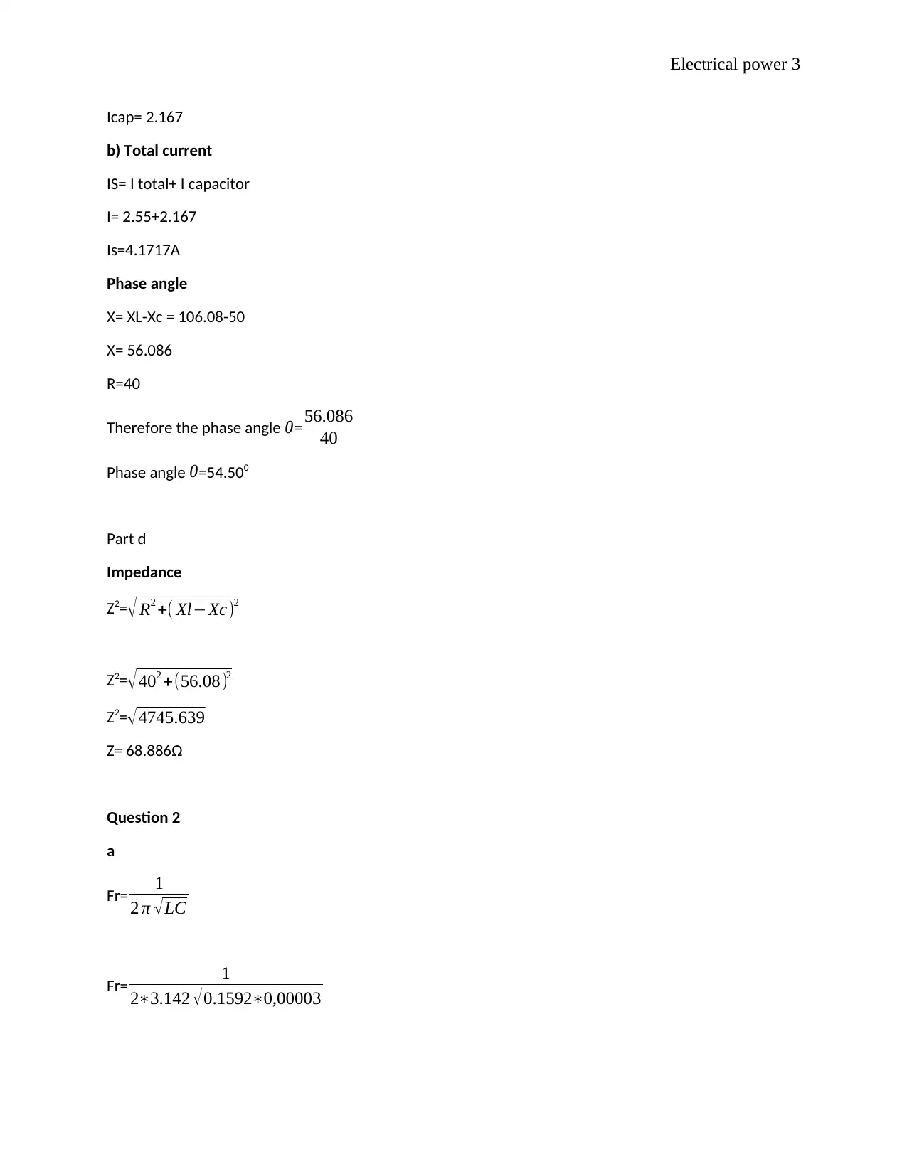
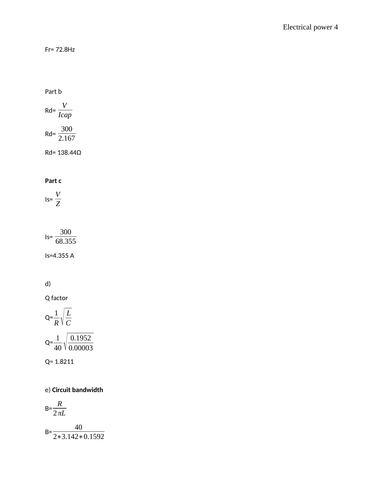
This document presents a detailed solution to an electrical power assignment, covering key concepts in electrical engineering. The solution addresses multiple questions, including calculations of inductive reactance, capacitive reactance, coil current, capacitor current, total current, and phase a...

Electrical power 1
ELECTRICAL POWER
By Name
Course
Instructor
Institution
Location
Date
ELECTRICAL POWER
By Name
Course
Instructor
Institution
Location
Date
Paraphrase This Document
Need a fresh take? Get an instant paraphrase of this document with our AI Paraphraser

Electrical power 2
Question 1
a)
XL= 2πfL
XL= 2*3.142*50*0.1592
XL=50.02
XC= 1
2 πfC
XC= 1
2∗3.142∗50∗0.00003
XC=106.089
Coil current
I= V
XL+R
I= 230
90.020
I=2.55A
Capacitor current
I= V
XC
I= 230
106.089
Question 1
a)
XL= 2πfL
XL= 2*3.142*50*0.1592
XL=50.02
XC= 1
2 πfC
XC= 1
2∗3.142∗50∗0.00003
XC=106.089
Coil current
I= V
XL+R
I= 230
90.020
I=2.55A
Capacitor current
I= V
XC
I= 230
106.089

Electrical power 3
Icap= 2.167
b) Total current
IS= I total+ I capacitor
I= 2.55+2.167
Is=4.1717A
Phase angle
X= XL-Xc = 106.08-50
X= 56.086
R=40
Therefore the phase angle θ= 56.086
40
Phase angle θ=54.500
Part d
Impedance
Z2=√ R2 +( Xl−Xc)2
Z2=√402 +(56.08)2
Z2=√4745.639
Z= 68.886Ω
Question 2
a
Fr= 1
2 π √LC
Fr= 1
2∗3.142 √0.1592∗0,00003
⊘ This is a preview!⊘
Do you want full access?
Subscribe today to unlock all pages.

Trusted by 1+ million students worldwide

Electrical power 4
Fr= 72.8Hz
Part b
Rd= V
Icap
Rd= 300
2.167
Rd= 138.44Ω
Part c
Is= V
Z
Is= 300
68.355
Is=4.355 A
d)
Q factor
Q= 1
R √ L
C
Q= 1
40 √ 0.1952
0.00003
Q= 1.8211
e) Circuit bandwidth
B= R
2 πL
B= 40
2∗3.142∗0.1592
Fr= 72.8Hz
Part b
Rd= V
Icap
Rd= 300
2.167
Rd= 138.44Ω
Part c
Is= V
Z
Is= 300
68.355
Is=4.355 A
d)
Q factor
Q= 1
R √ L
C
Q= 1
40 √ 0.1952
0.00003
Q= 1.8211
e) Circuit bandwidth
B= R
2 πL
B= 40
2∗3.142∗0.1592
Paraphrase This Document
Need a fresh take? Get an instant paraphrase of this document with our AI Paraphraser

Electrical power 5
B= 39.98Hz
Part f
The usage of the higher power factor help in reducing the amount of reactive power which in most
cases result to wastage power for 3 phase power supply. And some prototype calculation includes the
following
B= 39.98Hz
Part f
The usage of the higher power factor help in reducing the amount of reactive power which in most
cases result to wastage power for 3 phase power supply. And some prototype calculation includes the
following

Electrical power 6
Question 3
Part a
Current drawn
From P=VI
3000= 300 I
300
I= 10 A
b).
Actual P.F = 0.8
Required P.F = 0.95
θ1= 36.8990
θ2= 18.1940
Intended capacitor
Tanθ 1 -Tanθ 2
0.795079 – 0.32866 = 0.4221
3000 (0.4221)
= 1.266 kVAR
C= kVAR
2 πf V 2
Question 3
Part a
Current drawn
From P=VI
3000= 300 I
300
I= 10 A
b).
Actual P.F = 0.8
Required P.F = 0.95
θ1= 36.8990
θ2= 18.1940
Intended capacitor
Tanθ 1 -Tanθ 2
0.795079 – 0.32866 = 0.4221
3000 (0.4221)
= 1.266 kVAR
C= kVAR
2 πf V 2
⊘ This is a preview!⊘
Do you want full access?
Subscribe today to unlock all pages.

Trusted by 1+ million students worldwide

Electrical power 7
C= 1266
2∗3.142∗3002
C= 1266
28278000
C= 44.769 μF
Part c
(0.795079 – 0.32866) 3000 = 1266 kVAR
Original kVAR = (0.795079*3000) = 2252.38
Percentage reduction = 2252.38−1266
2252.38 × 100
Percentage reduction =43.792 %
Part d
C= 1266
2∗3.142∗3002
C= 1266
28278000
C= 44.769 μF
Part c
(0.795079 – 0.32866) 3000 = 1266 kVAR
Original kVAR = (0.795079*3000) = 2252.38
Percentage reduction = 2252.38−1266
2252.38 × 100
Percentage reduction =43.792 %
Part d
Paraphrase This Document
Need a fresh take? Get an instant paraphrase of this document with our AI Paraphraser

Electrical power 8
Question 4
Advantages of 3 phase includes the following
Star connection
Diagram
L= 32mH
R=8Ω
V= 415 Hz
XL= 2*3.142*50*0.032
XL=10.0544 Ω
Vph= VL
√3
Question 4
Advantages of 3 phase includes the following
Star connection
Diagram
L= 32mH
R=8Ω
V= 415 Hz
XL= 2*3.142*50*0.032
XL=10.0544 Ω
Vph= VL
√3

Electrical power 9
Vph= 415
√ 3 = 239.6 V
Total power dissipated in star connection
P=3I2R
I= 239.6
18.05
I=13.274
P= 3*13.2742*8
P= 4228.77 Watts
Delta connection
VL=VPH =239.6
IL= √3 IPh
IL= √3∗13.274
IPh= 6.310A
Total dissipated power
P= √3 VL* IL*Cos θ
P= √3 239.6* 6.310*120
P= 1309.4 Watts
Vph= 415
√ 3 = 239.6 V
Total power dissipated in star connection
P=3I2R
I= 239.6
18.05
I=13.274
P= 3*13.2742*8
P= 4228.77 Watts
Delta connection
VL=VPH =239.6
IL= √3 IPh
IL= √3∗13.274
IPh= 6.310A
Total dissipated power
P= √3 VL* IL*Cos θ
P= √3 239.6* 6.310*120
P= 1309.4 Watts
⊘ This is a preview!⊘
Do you want full access?
Subscribe today to unlock all pages.

Trusted by 1+ million students worldwide

Electrical power 10
References
Lam, C.-S., 2016. Parallel Power Electronics Filters in Three-Phase Four-Wire Systems: Principle, Control
and Design. 3rd ed. Liverpool: Springer.
Sensarma, P., 2017. Design and Control of Matrix Converters: Regulated 3-Phase Power Supply and
Voltage Sag Mitigation for Linear Loads. 2nd ed. Chicago: Springer.
1 out of 10

Your All-in-One AI-Powered Toolkit for Academic Success.
+13062052269
info@desklib.com
Available 24*7 on WhatsApp / Email
Unlock your academic potential
© 2024 | Zucol Services PVT LTD | All rights reserved.