Assignments Electrical Power Safety
VerifiedAdded on 2022/09/27
|13
|2623
|19
AI Summary
Contribute Materials
Your contribution can guide someone’s learning journey. Share your
documents today.
Electrical power 1
SAFETY SYSTEMS
Authors Name/s per 1st Affiliation (Author)
Dept. name of the organization
Name of organization, acronyms acceptable
City, Country
mail address
Authors Name/s per 2nd Affiliation (Author)
Dept. name of the organization
Name of organization, acronyms acceptable
City, Country
e-mail address
Question 1
Secure Best Marks with AI Grader
Need help grading? Try our AI Grader for instant feedback on your assignments.
Electrical power 2
What is a proof-test and what is proof test coverage?
Proof test is a form of stress test which is conducted to show the fitness of a load-bearing
structure. Proof testing is very vital part of the lifecycle safety and it is very significant to ensure
the system achieve its specific safety integrity level in the safety lifecycle. While proof test
coverage is simply a measure of the number of undetected dangerous failure which can be
detected through the use of proof test. And when these failures are detected it becomes easier to
be tackled. And a perfect example of a proof test is nondestructive test like ultrasonic.
Question 2.
What is a Process Hazard Analysis (PHA) and who conducts them?
Process Hazard Analysis normally known as PHA is a systematic technique of
identifying as well as evaluating all the risks which can be involved in any particular industrial
process so as to control, reduce or prevent the hazard from happening completely [1]. And most
cases it is conducted by facilitator or team leader who work with workers who understands all
the processes of doing the Process Hazard Analysis [2]. Performing process hazard analysis is
good for the engineering practice and the company which processes very dangerous chemicals.
This will highly help to protect the employees, environment where this company is situated and
the public from causing accident. The PHA helps protecting against the property damage,
process downtime, product quality issues and the adverse publicity accident. For the PHA, a
good example is the use of chemicals to help in prevention of some accidents like fire [2]. There
are some chemicals which are highly inflammable while others can result to fire when reacted
with others.
Electrical power 3
Question 3
What is MTBF and can it provide useful data for the calculation of PFDavg (average
probability of failure upon demand) considering perfect inspection, and if a constant
failure rate is assumed for the device?
Mean Time Between Failure is a measure of reliability of a hardware product or component.
And for several component this value is always given in thousands and some cases in tens of
thousands of hours between the failure [1]. This unit of measurement involves only the operation
duration between failures but it cannot include the duration for repair. And it is impossible for
the Mean Time Between Failure to provide useful data for the calculation of PFDavg. This is
because Probability of Failure on Demand average (PFDavg) is actually a probability which a
system will fail dangerously and not capable to conduct its function safety when needed. For
example a hard drive can have an average time between failure to be 270 000 hours Therefore t a
suitable MTFB can be employed as a quantifiable objective while designing another new hard
disk drive.
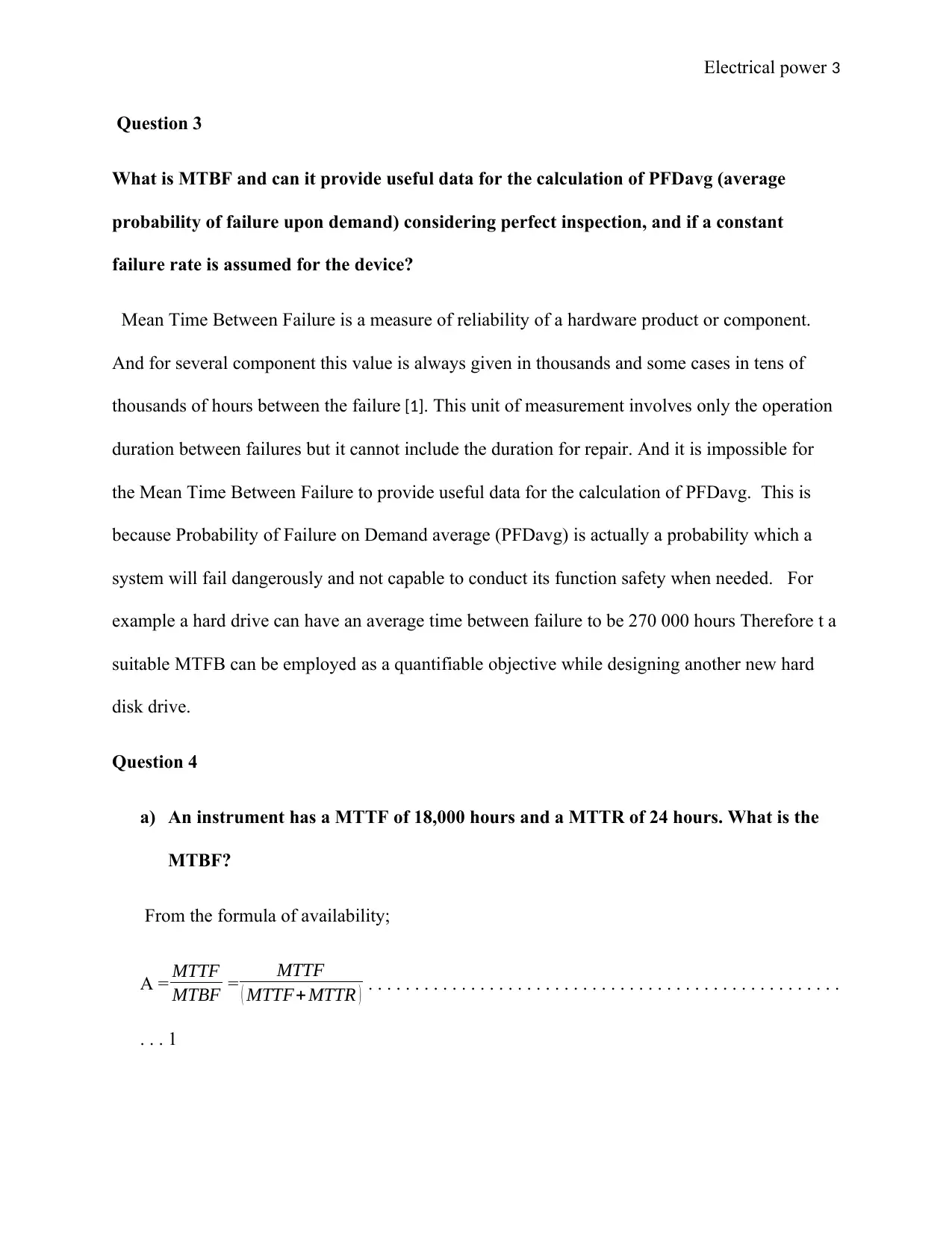
Question 4
a) An instrument has a MTTF of 18,000 hours and a MTTR of 24 hours. What is the
MTBF?
From the formula of availability;
A = MTTF
MTBF = MTTF
( MTTF+ MTTR ) . . . . . . . . . . . . . . . . . . . . . . . . . . . . . . . . . . . . . . . . . . . . . . . . . . .
. . . 1
Question 3
What is MTBF and can it provide useful data for the calculation of PFDavg (average
probability of failure upon demand) considering perfect inspection, and if a constant
failure rate is assumed for the device?
Mean Time Between Failure is a measure of reliability of a hardware product or component.
And for several component this value is always given in thousands and some cases in tens of
thousands of hours between the failure [1]. This unit of measurement involves only the operation
duration between failures but it cannot include the duration for repair. And it is impossible for
the Mean Time Between Failure to provide useful data for the calculation of PFDavg. This is
because Probability of Failure on Demand average (PFDavg) is actually a probability which a
system will fail dangerously and not capable to conduct its function safety when needed. For
example a hard drive can have an average time between failure to be 270 000 hours Therefore t a
suitable MTFB can be employed as a quantifiable objective while designing another new hard
disk drive.
Question 4
a) An instrument has a MTTF of 18,000 hours and a MTTR of 24 hours. What is the
MTBF?
From the formula of availability;
A = MTTF
MTBF = MTTF
( MTTF+ MTTR ) . . . . . . . . . . . . . . . . . . . . . . . . . . . . . . . . . . . . . . . . . . . . . . . . . . .
. . . 1
Electrical power 4
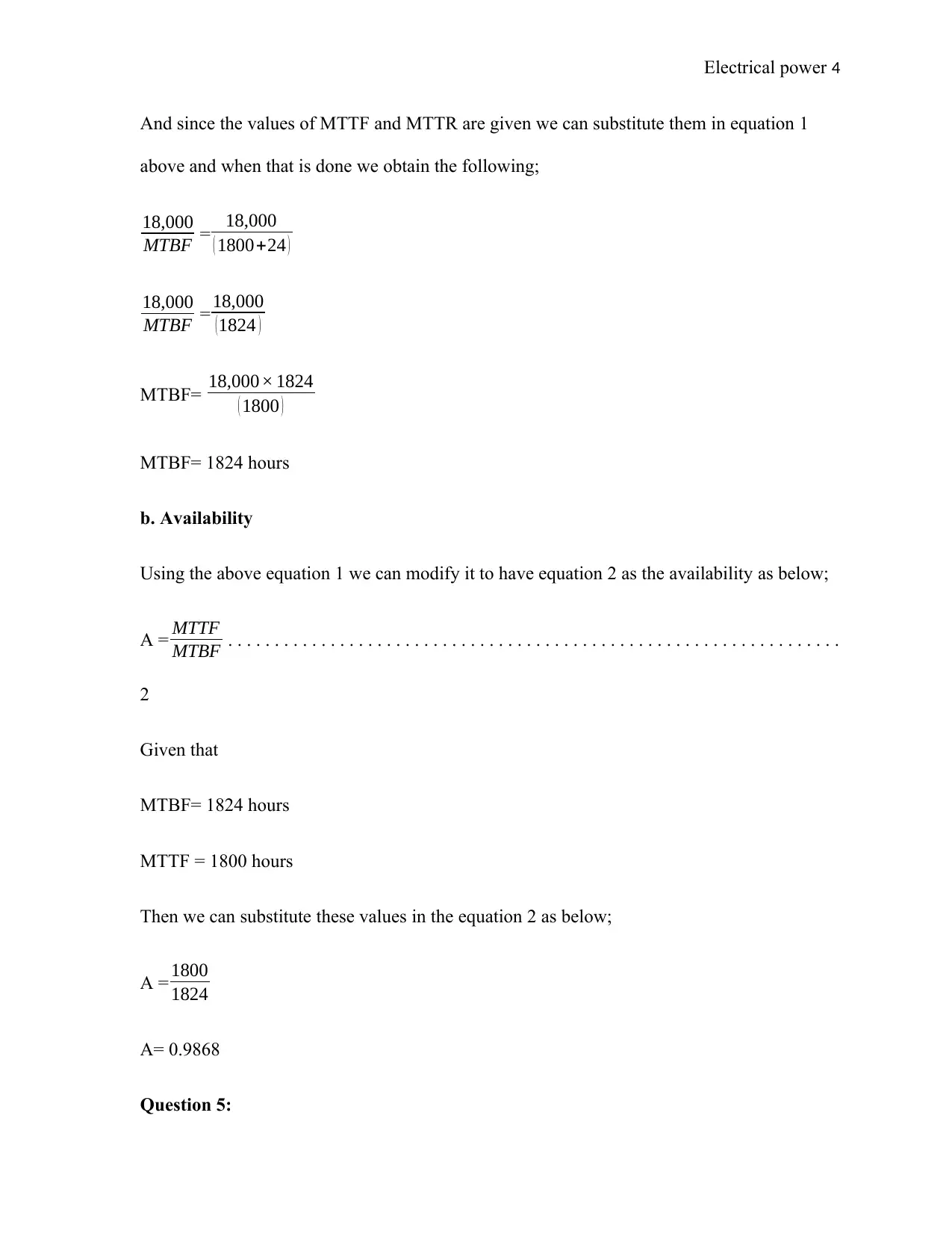
And since the values of MTTF and MTTR are given we can substitute them in equation 1
above and when that is done we obtain the following;
18,000
MTBF = 18,000
( 1800+24 )
18,000
MTBF = 18,000
(1824 )
MTBF= 18,000× 1824
( 1800 )
MTBF= 1824 hours
b. Availability
Using the above equation 1 we can modify it to have equation 2 as the availability as below;
A = MTTF
MTBF . . . . . . . . . . . . . . . . . . . . . . . . . . . . . . . . . . . . . . . . . . . . . . . . . . . . . . . . . . . . . . . . . .
2
Given that
MTBF= 1824 hours
MTTF = 1800 hours
Then we can substitute these values in the equation 2 as below;
A = 1800
1824
A= 0.9868
Question 5:
Secure Best Marks with AI Grader
Need help grading? Try our AI Grader for instant feedback on your assignments.
Electrical power 5
In accordance with IEC61508 “demands” and “demand mode” are two important
issues to address during a risk assessment of the EUC (Equipment Under Control).
a) What is meant by the term demand?
Demand is when perilous situation is present which can be detected by a SIF sensor hence the
SIF action is needed to avoid the progression to a dangerous event. Therefore when the demand
is high it will hence require a quick attention / frequent to ensure that perilous or risky situation
is avoided. For example if a motor is prone to production of a lot of noise (or other moving parts
in an industry) then attention need to be given to such parts before the part get highly destroyed
which can results to many issues.
b) What is meant by the term demand mode?
The demand mode is when the demand in activating the safety Instrumented function (known as
SIF) are uncommon as compared to the interval of test for the SIF [2]. Therefore for the low
demand mode the demand activates tone SIF are always less than doing two proof test. And the
low the demand mode of the operation the most common demand mode in the manufacturing
companies. And the example of the demand mode includes the low mode and high mode just as
explained above in this question.
Question 6:
The Safety Requirements Specification (SRS) is a key document for the design of a safety
instrumented system (SIS). Describe briefly the main contents of an SRS and at what
phase(s) in the safety lifecycle it is developed.
Electrical power 6
Contents of an SRS
As for this specification requirements, it needs to highlight how accurate the information it
contains is very vital to make sure that there is no misinterpretation or ambiguity of the
requirements, this is true processes which are safety related [3]. For the standards of IEC61511
it is performance based where all operations of the SIS as well as risk reduction are done in a
very clear way on what the content of SRS should be. Therefore these content are all the safety
requirement and the linked safety instrumented Functions ( SIFs ) that have combination of logic
solvers, sensors and final elements, this including power sources and all interfaces [4]. Hence the
SRS requires a defined 2 sets of criteria for every SIF. And these include set of integrity
requirements showing the risk reduction to be realized. It also include the set of functional
requirements.
Phase in the safety lifecycle
The phases in the lifecycle it is developed include the following;
i. Safe test. Which is the process of achieving the process. The activities in this phase
include the below;
successive shutdown
Which process valve(s) is required to do a particular action at the safe state. Shall the
valve open or close?
which flows ought to be began or stopped
start , stop or continue operation of rotating elements for example motor and pump
Electrical power 7
ii. Proof test intervals. This is a very vital test which is considered when designing the
process application because this test affect the application design. And the activities
carried out in this case include the below;
describe the procedures of proof test
Examine if extra safety measures such as redundancy and monitoring has to
be adapted during the interval of the proof test.
Examine if human aspects could interfere the safety during the proof test
particularly when the consequences could be disastrous if the proof test go is
wrong.
stipulate the obligatory proof tests during the life-cycle
the proof test activity will be documented
iii. Response time.
This is the requirement for the SIS which brings the whole process to a safe state.
iv. Reset time. This is a balanced and healthy time management design which need to be
sufficient for obtaining the preparation, fun and growth of the industry operation.
Question 7:
Failure analysis usually includes the identification of failure modes. What do we mean by
the term “failure mode”?
The failure mode is a way in which machine or equipment failure can occur. In other
words failure mode is one possible way through which a system can fail [2]. Hence when a
system has several potential ways of failing thus it can be said to have a several failure mode or
Paraphrase This Document
Need a fresh take? Get an instant paraphrase of this document with our AI Paraphraser
Electrical power 8
in some cases it is referred to as competing risks [8]. Taking an example of a burglar alarm, for
instance, doesn´t have just a singular failure mode. This is because it can fail due to the defective of heat
sensor and motion sensor or even in problem in wiring of the system. The failure of this alarm can also
be due to the dead, faulty or missing of the battery of the alarm. A perfect example of failure mode
can be taken for a bank which does ATM operation, its function is to dispense cash and it can
have some failure mode for it function. Its failure mode is always checked to be very low since it
deals with very sensitive product which can lead to a big loss if its failure mode is really high.
Question 8:
Referencing the failure classification in IEC 61508, what are the different failure mode(s).
What is the most important failure mode and the one used for calculating PFDavg.
There are several different types of failure mode, we will talk about five different types of
failure modes.
1. Fracture: This is a failure mode which is as a result of a crack which appears. And when
this this occur in a material the structure can completely break. It basically starts due to
tension forces. And it has extensively been illustrated using the following diagram;
Electrical power 9
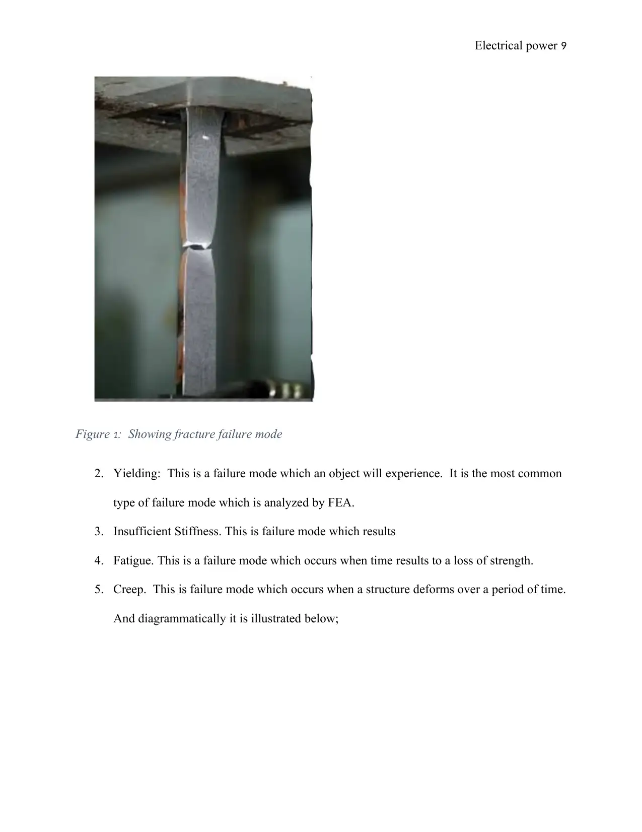
Figure 1: Showing fracture failure mode
2. Yielding: This is a failure mode which an object will experience. It is the most common
type of failure mode which is analyzed by FEA.
3. Insufficient Stiffness. This is failure mode which results
4. Fatigue. This is a failure mode which occurs when time results to a loss of strength.
5. Creep. This is failure mode which occurs when a structure deforms over a period of time.
And diagrammatically it is illustrated below;
Electrical power 10
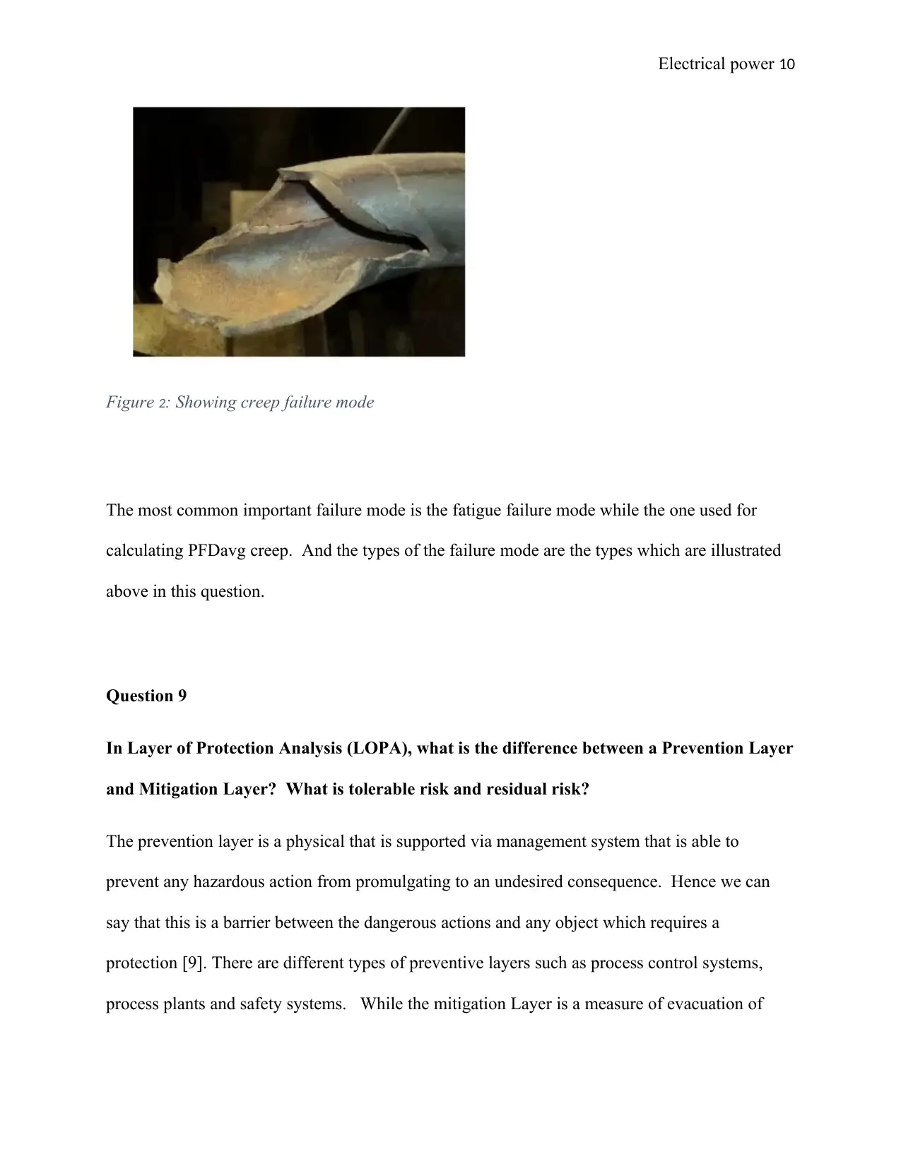
Figure 2: Showing creep failure mode
The most common important failure mode is the fatigue failure mode while the one used for
calculating PFDavg creep. And the types of the failure mode are the types which are illustrated
above in this question.
Question 9
In Layer of Protection Analysis (LOPA), what is the difference between a Prevention Layer
and Mitigation Layer? What is tolerable risk and residual risk?
The prevention layer is a physical that is supported via management system that is able to
prevent any hazardous action from promulgating to an undesired consequence. Hence we can
say that this is a barrier between the dangerous actions and any object which requires a
protection [9]. There are different types of preventive layers such as process control systems,
process plants and safety systems. While the mitigation Layer is a measure of evacuation of
Secure Best Marks with AI Grader
Need help grading? Try our AI Grader for instant feedback on your assignments.
Electrical power 11
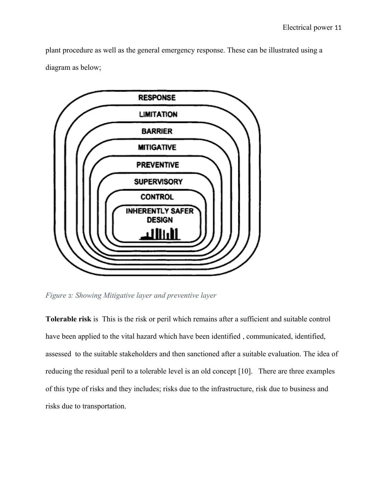
plant procedure as well as the general emergency response. These can be illustrated using a
diagram as below;
Figure 3: Showing Mitigative layer and preventive layer
Tolerable risk is This is the risk or peril which remains after a sufficient and suitable control
have been applied to the vital hazard which have been identified , communicated, identified,
assessed to the suitable stakeholders and then sanctioned after a suitable evaluation. The idea of
reducing the residual peril to a tolerable level is an old concept [10]. There are three examples
of this type of risks and they includes; risks due to the infrastructure, risk due to business and
risks due to transportation.
Electrical power 12
Residual risk is a type of risk which is also known as inherent risk and it is the balance of risk
which is exposed after acting and identifying on all well-known threats. Basically this is the risk
which shows that there will be a loss which cause a threat which is not taken into consideration
and it not identified. The residual risk can be obtained using the following equation;
Residual risk = inherent risk – impact of risk control . . . . . . . . . . . . . . . . . . . . . . . . . . . . . . . . . 1
And some example of residual risks includes the risk reduction, risk avoidance, risk acceptance
and the risk transfer.
Electrical power 13
Bibliography
[1] S. Mannan, Lees' Process Safety Essentials: Hazard Identification, Assessment and Control,
Liverpool: Butterworth-Heinemann, 2013.
[2] B. Skelton, Process Safety Analysis: An Introduction, London: IChemE, 2017.
[3] N. Hyatt, Guidelines for Process Hazards Analysis (PHA, HAZOP), Hazards Identification, and Risk
Analysis, Hull: CRC Press, 2018.
[4] J. J. Heldt, Quality Sampling and Reliability: New Uses for the Poisson Distribution, Hull: CRC Press,
2011.
[5] D. Smith, Reliability, Maintainability and Risk: Practical Methods for Engineers including Reliability
Centred Maintenance and Safety-Related Systems, Chicago: Elsevier, 2012.
[6] T. Kalal, Improving Product Reliability: Strategies and Implementation, Liverpool: John Wiley &
Sons, 2013.
[7] D. Kececioglu, Reliability Engineering Handbook, Liverpool: DEStech Publications, Inc, 2012.
[8] A. Babiker, Failure Mode and Effect Analysis (FMEA) May Enhance Implementation of Clinical
Practice Guidelines: An Experience from the Middle East, London: Jonh Wiley & Sons Limited, 2017.
[9] S. Anorld, Advances in Fire and Process Safety: Select Proceedings of HSFEA 2016, Liverpool:
Springer, 2018.
[10] O. Renn, Risk Governance: Coping with Uncertainty in a Complex World, Hull: Taylor & Francis,
2017.
[11] W. Middleton, Reference Data for Engineers, Stoke: CRC, 2013.
1 out of 13
Related Documents

Your All-in-One AI-Powered Toolkit for Academic Success.
+13062052269
info@desklib.com
Available 24*7 on WhatsApp / Email
![[object Object]](/_next/static/media/star-bottom.7253800d.svg)
Unlock your academic potential
© 2024 | Zucol Services PVT LTD | All rights reserved.