Comparison of word and bit values
Added on 2022-09-07
14 Pages3573 Words22 Views
ELECTRONICS
Comparison of word and bit values
1. Using micrologic 1100 PLC as an example; list any five of the basic file types, and for
file type list the number of memory words each element consumes and describe type of
data stored in the file.
The micrologic 1100PLC contains 11 basic file types. They include;
Output- the file number is 0 and the element number is used to set I/O slot. In
addition, the word offset sets the words within the I/O slot.
Input- the file number is 1 and the element number is used to set I/O slot. In addition,
the word offset sets the words within the I/O slot.
Status- the file number is 2 and the element number is used to set the status word. In
addition, the word offset sets the words within the I/O slot and the bit offsets set the
bits within 0-15.
Bit- the file number is either 3 or sets the bit file to use bits between (3, 9-255). The
element sets the word and the bit offset is within 0-15 range.
Timer- the file number is either 4 or sets the timer file to use (4, 9-255). The element
number sets the timer index, the word offset sets the word offset within 0-2 range and
the bit offsets set the bits within 0-15.
2. The difference between integer and floating point numbers and practical examples for
each use.
An integer number is a set of data that is expressed as whole numbers and do not have any
fractions parts while floating point numbers are fixed specific number of bits that are arranged to
contain both whole number and fraction part. In short this means that integer data is presented in
decimal, octal or hexadecimal systems while floats are presented only in decimal number system.
Examples of integer include -125, 567, and 4,667 while examples of floating point numbers
include 1.2e34, and 0.98.
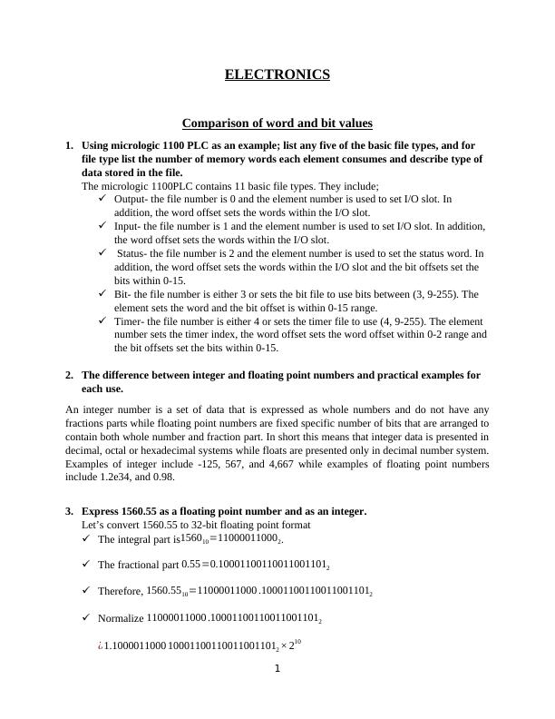
3. Express 1560.55 as a floating point number and as an integer.
Let’s convert 1560.55 to 32-bit floating point format
The integral part is156010=110000110002.
The fractional part 0.55=0.100011001100110011012
Therefore, 1560.5510=11000011000 .100011001100110011012
Normalize 11000011000 .100011001100110011012
¿ 1.1000011000 100011001100110011012 × 210
1
Comparison of word and bit values
1. Using micrologic 1100 PLC as an example; list any five of the basic file types, and for
file type list the number of memory words each element consumes and describe type of
data stored in the file.
The micrologic 1100PLC contains 11 basic file types. They include;
Output- the file number is 0 and the element number is used to set I/O slot. In
addition, the word offset sets the words within the I/O slot.
Input- the file number is 1 and the element number is used to set I/O slot. In addition,
the word offset sets the words within the I/O slot.
Status- the file number is 2 and the element number is used to set the status word. In
addition, the word offset sets the words within the I/O slot and the bit offsets set the
bits within 0-15.
Bit- the file number is either 3 or sets the bit file to use bits between (3, 9-255). The
element sets the word and the bit offset is within 0-15 range.
Timer- the file number is either 4 or sets the timer file to use (4, 9-255). The element
number sets the timer index, the word offset sets the word offset within 0-2 range and
the bit offsets set the bits within 0-15.
2. The difference between integer and floating point numbers and practical examples for
each use.
An integer number is a set of data that is expressed as whole numbers and do not have any
fractions parts while floating point numbers are fixed specific number of bits that are arranged to
contain both whole number and fraction part. In short this means that integer data is presented in
decimal, octal or hexadecimal systems while floats are presented only in decimal number system.
Examples of integer include -125, 567, and 4,667 while examples of floating point numbers
include 1.2e34, and 0.98.
3. Express 1560.55 as a floating point number and as an integer.
Let’s convert 1560.55 to 32-bit floating point format
The integral part is156010=110000110002.
The fractional part 0.55=0.100011001100110011012
Therefore, 1560.5510=11000011000 .100011001100110011012
Normalize 11000011000 .100011001100110011012
¿ 1.1000011000 100011001100110011012 × 210
1
The mantissa is1000011000 10001100110011001101, the exponent is
10+127=137=100010012 the sign bit is 0
Therefore 1560.55is 010001001100001100010001100110011001101 in the format;
0 10001001 100001100010001100110011001101
¿ 226188 CCCD16
4. What type of number can only be used for the preset values of timers and counters and
what is the largest value possible?
The preset value is defined as the total number of times the PLC timer counts before the state of
the output is changed. Timers and counters use bits in seconds and its multiples to preset values.
The method of allocating preset values for timers and counters varies from one PLC brand to
another and/or one series to another. The only way is to see the specifications of each brand; for
instance for AB MicroLogix series of PLC, the maximum possible value that can be assigned is
32767 with a maximum base of 1 second.
Installation and configuration of a PLC
1. Describe in detail what considerations must be taken when installing a PLC in a typical
industrial environment. Assume that the PLC is to be installed in a suitable enclosure.
Before a PLC equipment is installed in a typical industrial there are three main factors that
need to be considered. They are;
Conditions of the surrounding in the industry
How the components will be distributed in the enclosure that will contain the PLC
system.
Electrical power supply and wiring.
The physical environment in the industry where the PLC installations will be done has to
meet the following environmental conditions;
There should be minimal or no vibrations
The PLC system installations must not be exposed to direct sunlight
There should no dust nor saline conditions
Absence of both flammable and corrosive fluids
The enclosure carrying the PLC should be made of metal. The enclosure chosen, in addition,
should be of the right size to allow enough space for other devices to be installed such as a
fan to regulate the temperature of the enclosed environment and allow proper ventilation of
air. This will regulate the ambient temperature of the PLC and the specified temperature.
2
For correct wiring and power supply to be met the following should be adhered to;
Clear separation of cables conducting DC and AC supply to avoid confusion and
interference
Separate input and output cables
Separate analogue conductors from digital conductors
Use of switches and fuses to protect the PLC against overloads and short-circuiting.
Setting and checking of the PLC installations includes the following
Making sure that the cables and wires used for connections between the PLC system
and the plant are of the required standards and meets the specifications and safe for
use.
Making sure that the power supply that is input to the PLC system is within the
required voltage range set in the PLC.
Ensuring that all the devices used for protecting the PLC and the entire electrical
system are set to their required trip status.
Making sure of that all emergence stop buttons are working properly.
Ensuring that all input and output devices are paired to their correct respective points
and that they are giving proper signals.
2. Explain the difference between signal transmission as a current and as a current.
Provide examples of the standard signal types you would expect to encounter and how
to overcome issues associated with each type of the signal (current or voltage).
The practical difference is that the current signal is transmitted as current while the voltage
signal is transmitted as voltage. In depth the difference is that the current signal is induced by the
current with infinite high impedance thus meaning that the signal will be robust to disturbances
along the transmission line such as magnetic and electric fields in the surrounding which will in
turn induce voltage but no current because of high impedance, while the signal is induce by
voltage at low impedance.
3. Explain the term resolution when applied to a PLC analogue input or output.
Resolution of analogue signals is defined as the number of bits that are used to save the analogue
value in a PLC.
The analogue signal resolution is used when dealing with analogue input and output signals in
PLC programming. For instance inserting an analogue input card will lead to the analogue signal
being split into values ranging between 0 and 32.767. Division of analogue into 32.767 will give
a specific resolution.
4. Show by calculation, the smallest value that can be represented by a 10-bit digital to
analog converter on a 0-10V DC PLC analogue input module.
3
10-Bit DAC Converter
Voltage Output = Reference Voltage
2N−1 × Digital Number Input
¿ Vref
1023 × Din
Assuming that the reference voltage is 3.3V and digital input is 10 for 10-bit DAC
Therefore,
¿ 3.3
1023 ×10
¿ 0.032258 V
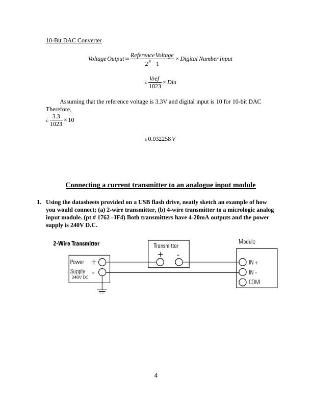
Connecting a current transmitter to an analogue input module
1. Using the datasheets provided on a USB flash drive, neatly sketch an example of how
you would connect; (a) 2-wire transmitter, (b) 4-wire transmitter to a micrologic analog
input module. (pt # 1762 –IF4) Both transmitters have 4-20mA outputs and the power
supply is 240V D.C.
4
Voltage Output = Reference Voltage
2N−1 × Digital Number Input
¿ Vref
1023 × Din
Assuming that the reference voltage is 3.3V and digital input is 10 for 10-bit DAC
Therefore,
¿ 3.3
1023 ×10
¿ 0.032258 V
Connecting a current transmitter to an analogue input module
1. Using the datasheets provided on a USB flash drive, neatly sketch an example of how
you would connect; (a) 2-wire transmitter, (b) 4-wire transmitter to a micrologic analog
input module. (pt # 1762 –IF4) Both transmitters have 4-20mA outputs and the power
supply is 240V D.C.
4
End of preview
Want to access all the pages? Upload your documents or become a member.
Related Documents
ITC544 Assignment on Data Representation and Digital Logiclg...
|5
|524
|87
Desklib - Online Library for Study Materiallg...
|9
|2530
|40
C++ programming questions on recursion, loops, classes, and data structureslg...
|6
|1265
|171