Wireless Communication Systems: Link Budget Analysis - VIT MITS5003
VerifiedAdded on 2023/03/30
|6
|546
|437
Homework Assignment
AI Summary
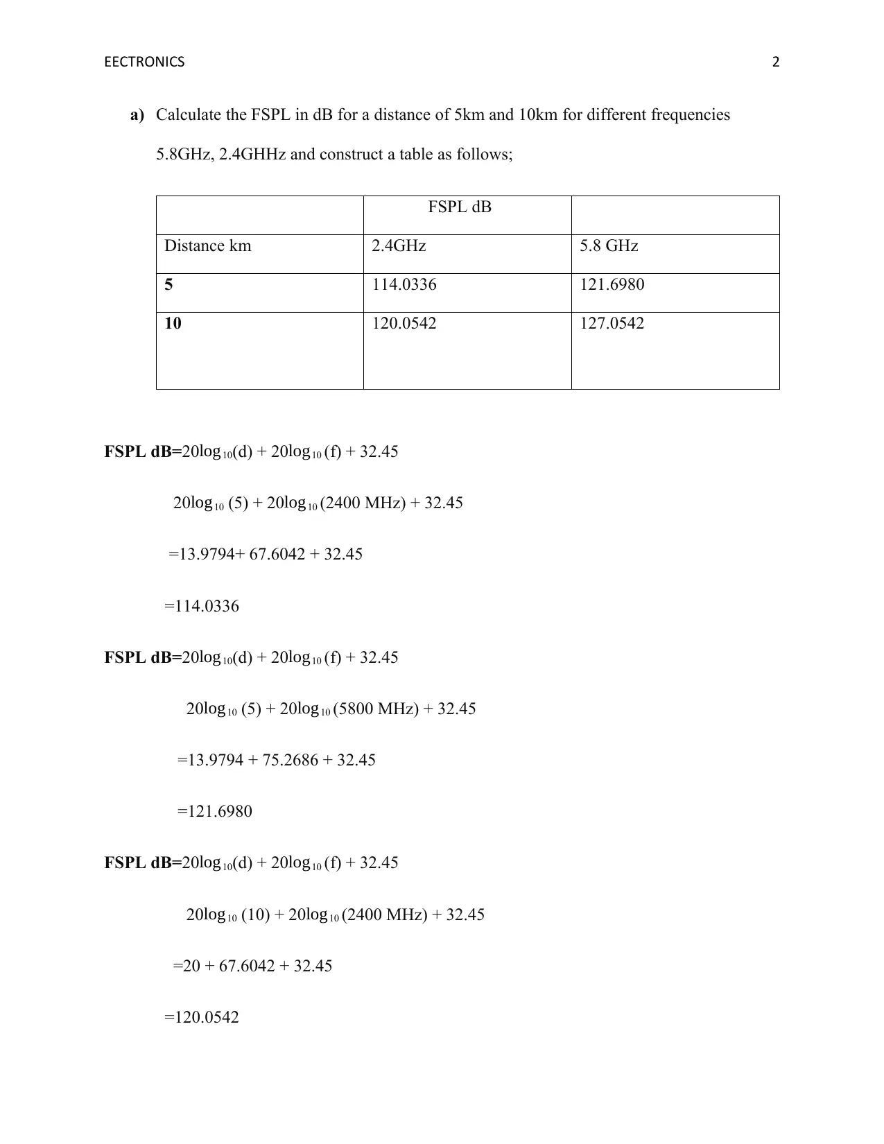
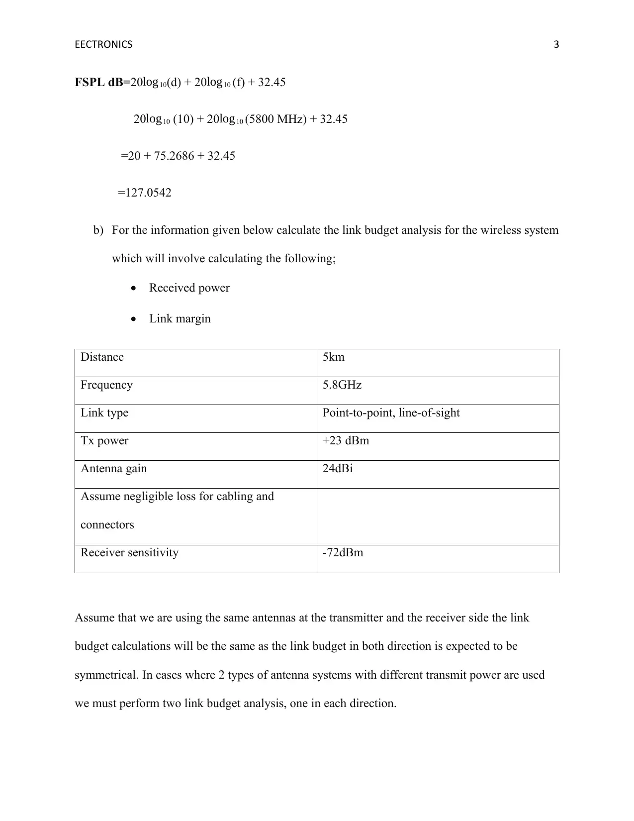
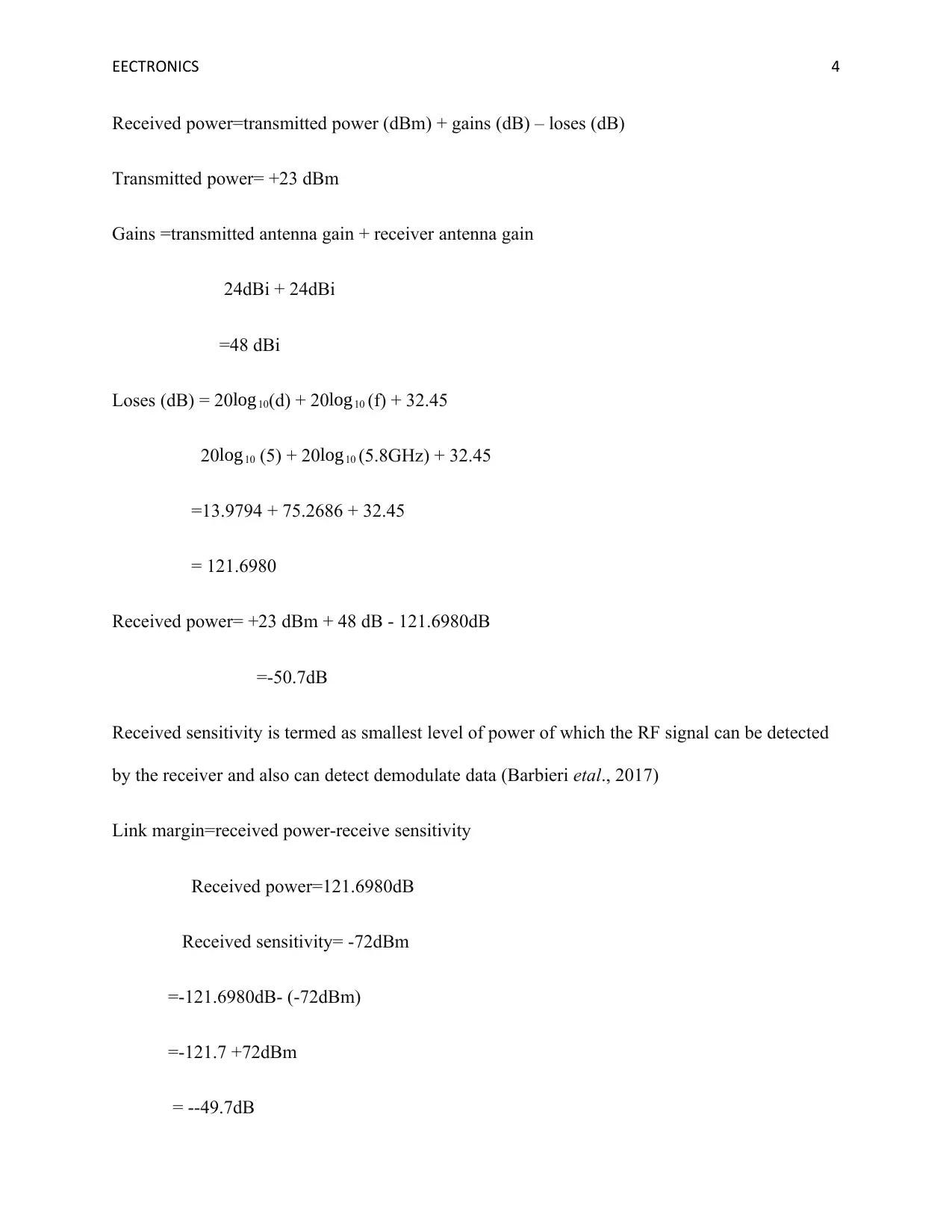
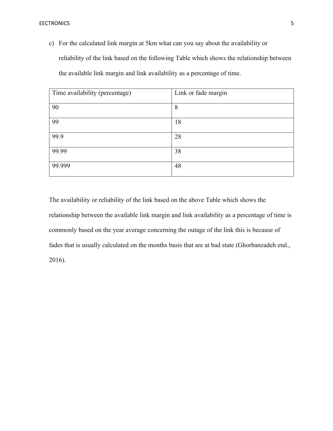
This assignment solution focuses on wireless communication systems, specifically addressing Free Space Path Loss (FSPL) calculations and link budget analysis. The FSPL is computed for distances of 5km and 10km at frequencies of 5.8GHz and 2.4GHz, and the results are presented in a table. Furthermore, a link budget analysis is performed for a point-to-point, line-of-sight wireless system operating at 5.8GHz over a 5km distance, including calculations for received power and link margin, considering transmitter power, antenna gains, and receiver sensitivity. The solution also interprets the link margin in terms of link availability and reliability based on a provided table, discussing the impact of fade margin on the percentage of time the link is available. This document is available on Desklib, a platform offering a wide range of study resources for students.
1 out of 6
Related Documents


Your All-in-One AI-Powered Toolkit for Academic Success.
+13062052269
info@desklib.com
Available 24*7 on WhatsApp / Email
![[object Object]](/_next/static/media/star-bottom.7253800d.svg)
Copyright © 2020–2026 A2Z Services. All Rights Reserved. Developed and managed by ZUCOL.