Embedded System Design: Microcontroller Comparison and Analysis
VerifiedAdded on 2021/04/24
|28
|5205
|21
Report
AI Summary
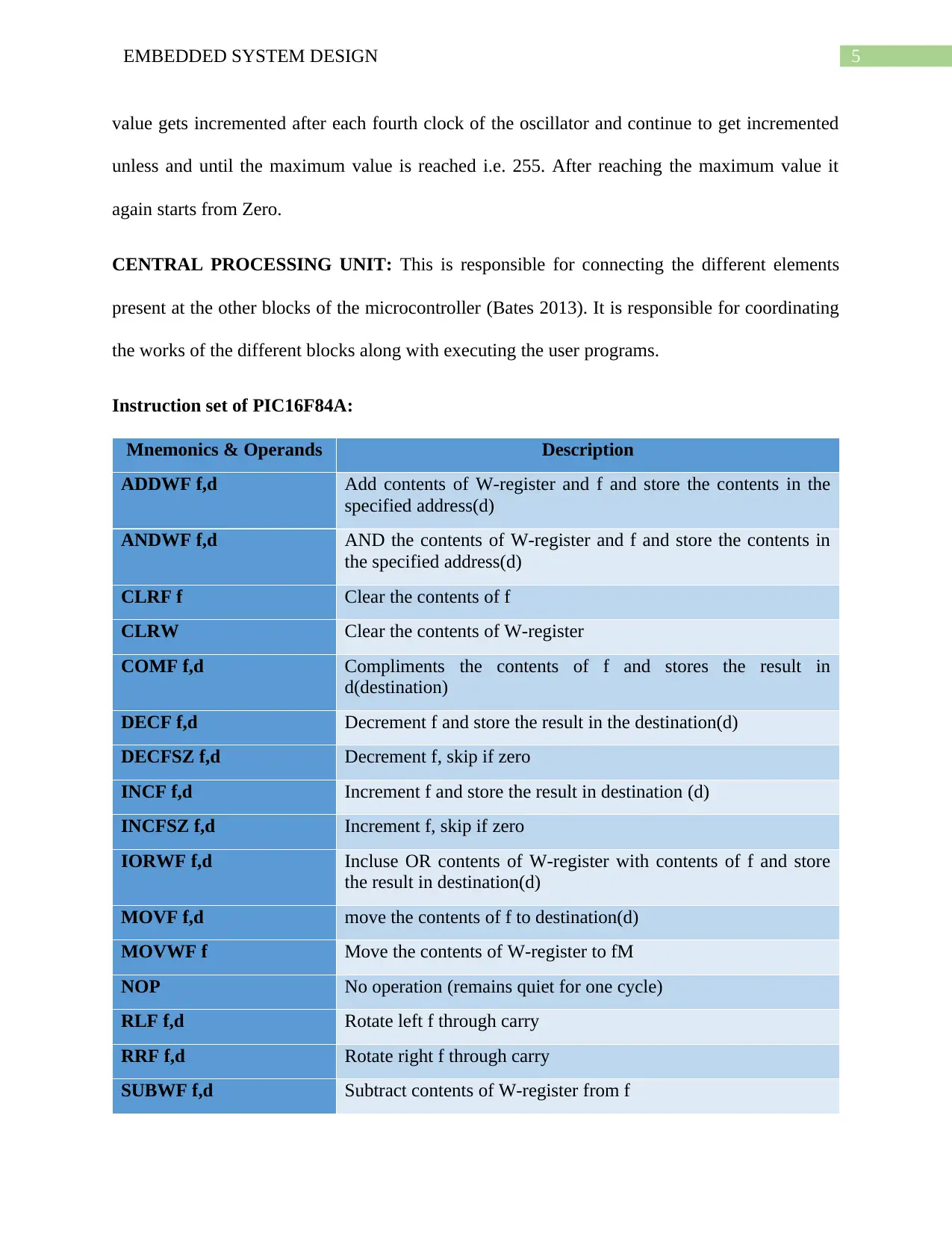
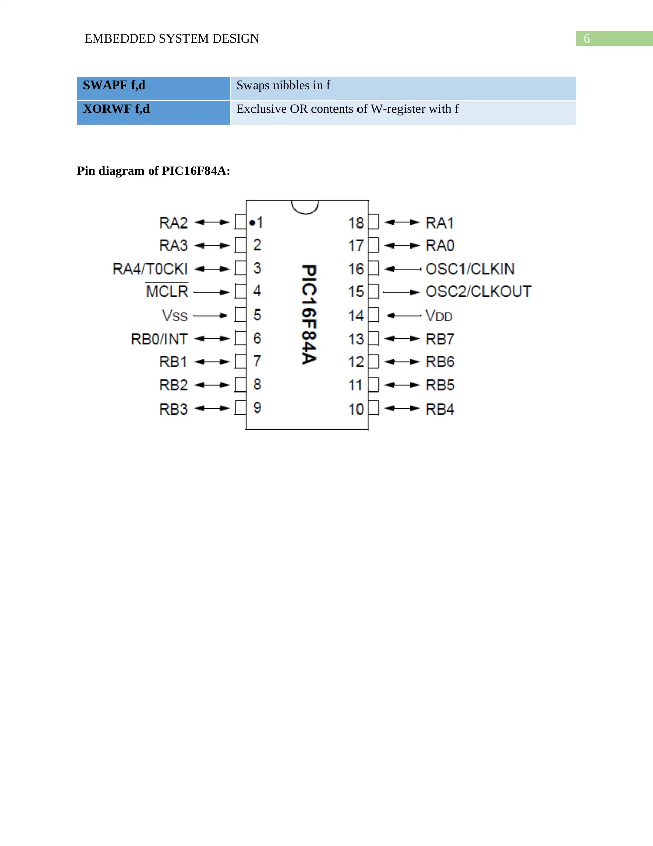
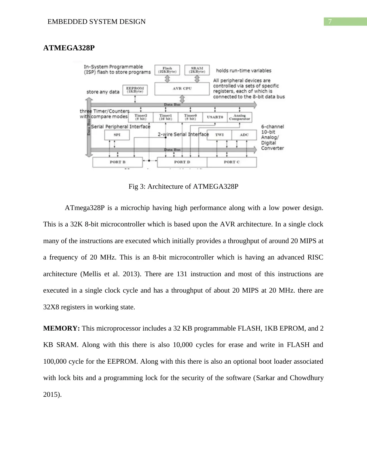
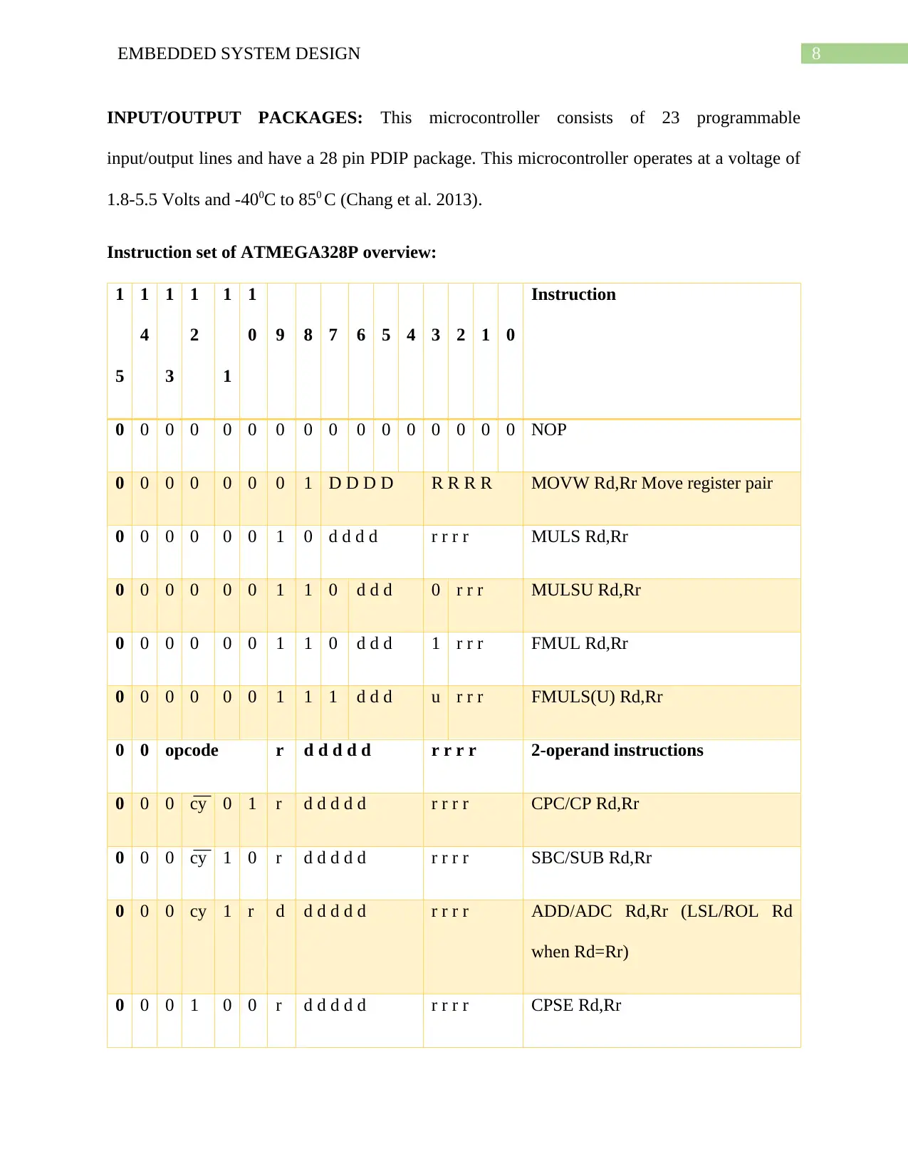
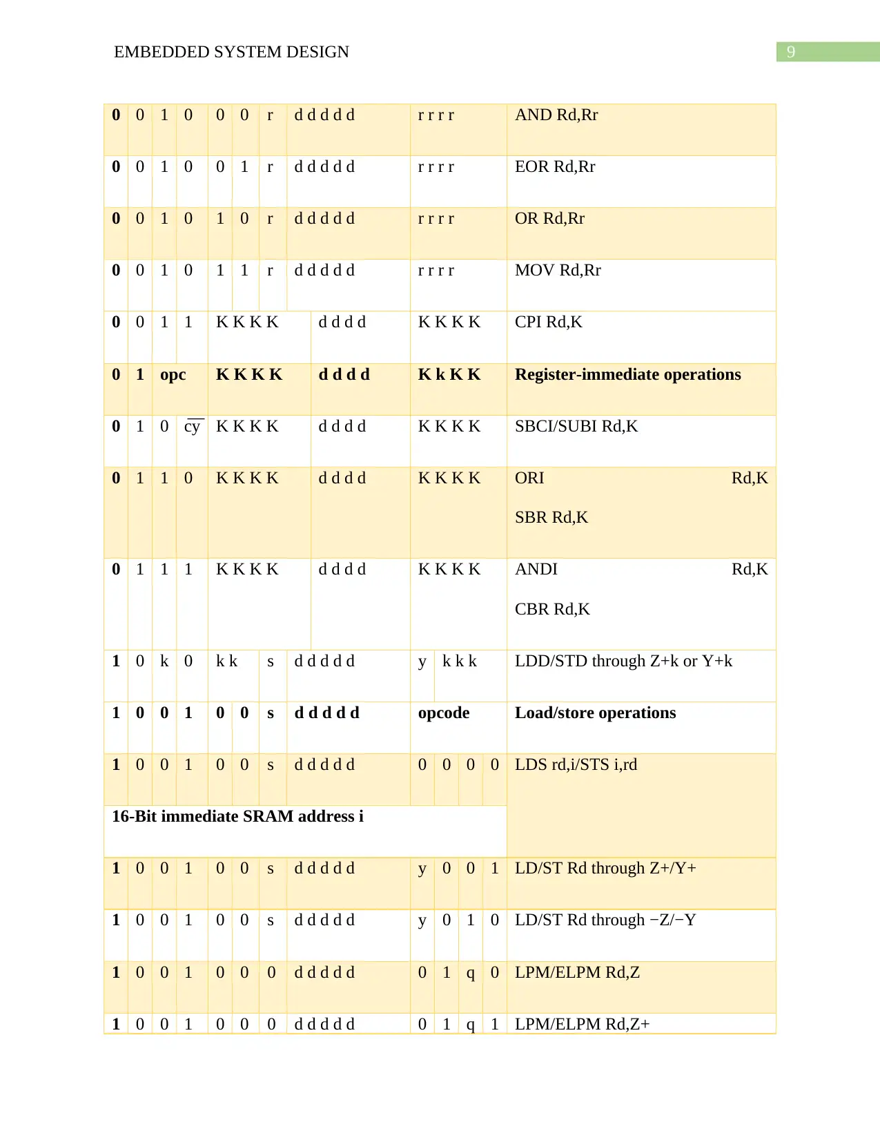
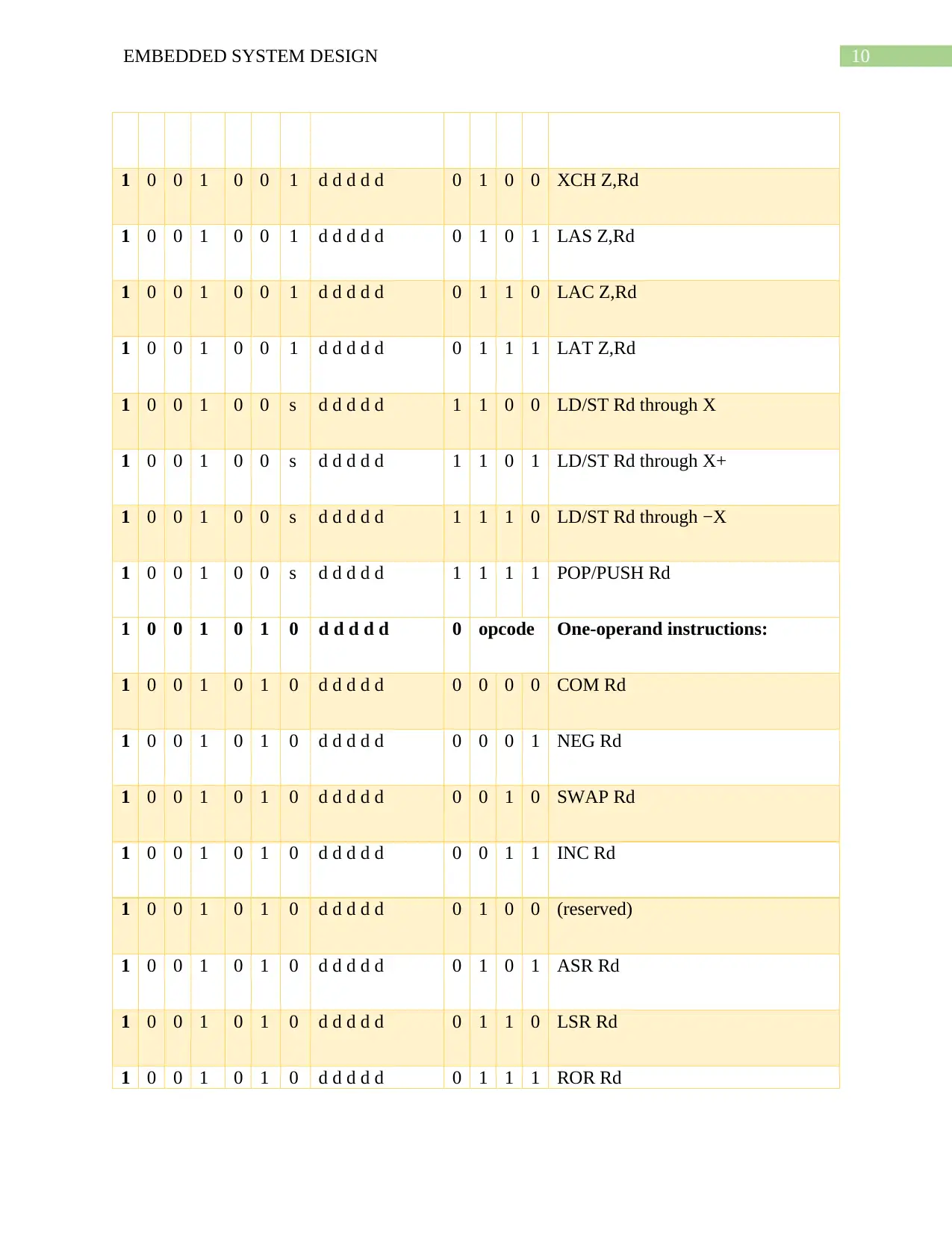
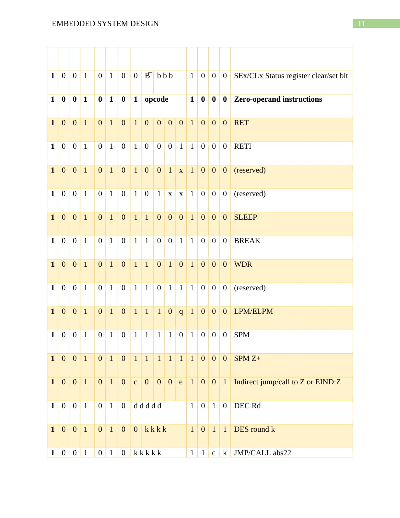
This report provides a comparative analysis of three microcontrollers: PIC16F84A, ATMEGA328P, and ATMEL89C51, crucial components in embedded system design. The report delves into each microcontroller's architecture, detailing components like CPU, memory (Flash, EEPROM, RAM), and input/output ports. It explores the instruction sets of each, providing mnemonics and descriptions for PIC16F84A and an overview of the ATMEGA328P and ATMEL89C51 instructions. Pin diagrams are presented to illustrate the physical connections and functionalities of each microcontroller. The discussion encompasses memory organization, peripherals, speed, cost, development tools, and potential applications of each microcontroller. The report concludes with a summary of the comparisons, highlighting strengths and weaknesses to aid in informed decision-making for embedded system projects. References are provided for further study and research.

1 out of 28
Related Documents


Your All-in-One AI-Powered Toolkit for Academic Success.
+13062052269
info@desklib.com
Available 24*7 on WhatsApp / Email
![[object Object]](/_next/static/media/star-bottom.7253800d.svg)
Copyright © 2020–2026 A2Z Services. All Rights Reserved. Developed and managed by ZUCOL.