EAC4025-N - Emerging Transmission System Lab Report: DC-AC Converters
VerifiedAdded on 2023/05/30
|26
|3679
|445
AI Summary
This lab report investigates high-power and voltage transmission systems through didactic hardware. It covers both HVDC and AC power transmission, examining parameters such as DC voltage influence, converter station analysis, and power flow. The AC Power Transmission section focuses on monitoring network parameters using SCADA and reducing peak loading through energy management, achieving a minimum peak value of 500W. The report also explores HVDC technology, including converter stations for AC-DC and DC-AC conversion, and discusses experimental methods and results, including load regulation experiments and signal modulation techniques. Key findings include the impact of DSM on peak values and the effects of hysteresis on load regulation. The report concludes with a discussion of the advantages of sinusoidal modulation over fundamental frequency control.

Emerging Transmission System 1
Lab Report on Emerging Transmission System
By
(Student’s Name)
Course Name:
Professor Name:
University Name:
Date of Submission:
Lab Report on Emerging Transmission System
By
(Student’s Name)
Course Name:
Professor Name:
University Name:
Date of Submission:
Paraphrase This Document
Need a fresh take? Get an instant paraphrase of this document with our AI Paraphraser

Emerging Transmission System 2
Table of Contents
Summary......................................................................................................................................5
Research background...................................................................................................................6
High-voltage Alternating current Experiments...........................................................................6
High-voltage Alternating current Technologies..........................................................................7
Experimental Methods and Results.............................................................................................8
Load Regulation Experiments.....................................................................................................9
Operational mode.......................................................................................................................12
Operation with signal modulation.............................................................................................13
Technical Analysis.....................................................................................................................23
Discussion..................................................................................................................................25
Conclusion.................................................................................................................................27
Bibliography..............................................................................................................................28
Emerging Transmission System 3
Summary
This assignment is a lab report which aims at examining the high power and voltage transmission
systems, and it is conducted through the use of the didactic hardware systems. In essence, the lab
report is divided into two primary sections which include an experiment on the HVDC or High
Voltage Power Transmission while the second section examines the AC Power Transmission.
Furthermore, the first section has various parameters which are examined, and these include
determining the DC voltage influence on the AC variables converter station and analysing the
single behavior of the HVDC converter results which are depicted during the capacitive and the
inductive reactive current supply. Also, the first section also evaluates the power flow associated
with the close coupling, the overall converter stations loss analysis as well as the operating
characteristics in line with the overhead wires. On the other hand, the second section aims at
evaluating the monitoring all the network parameters, and this is done using SCADA. Finally,
the AC Power Transmission also used to reduce the peak loading as a result of testing the energy
management in the system. Minimum peak value obtained at that stage is ∑Pmin = 500 W.
High-voltage Alternating current transmission also is known as the high-voltage direct-current
entails the transmission line and converter station which mainly operates to convert the
alternating grid and conventional electricity voltage to the direct voltage. Furthermore, the
HVDC transmission also has an end station converter, and this serves to convert the direct
voltage at the end of the system back to the alternating voltage. Also, this system is capable of
transmitting energy in both directions while the second converter station in the HVDC plays a
vital role in regulating the power in the system.
⊘ This is a preview!⊘
Do you want full access?
Subscribe today to unlock all pages.
Trusted by 1+ million students worldwide
Emerging Transmission System 4
Research background
Mostly, electrical power is distributed to the end-users once it has been generated and the
distribution is done via a transmission system to different located sites. The electric power
consumers are broadly divided into categories which include the commercial establishments and
the domestic acts [1] .Thus, the transmission lines will carry the power from the various
substations to the designated consumers in the long run. High-voltage Alternating current
(HVAC) is often suitable for shorter and medium distance transmissions of power whereas the
High voltage Direct Current also known as HVDC mainly operates for the long-distance
transmission. In addition, the HVAC is more economical when dealing with short distance and
have imminent disadvantages on long distances thus, making HVDC suitable for long distance
transmissions [2] .Hence, the theoretical research section for this lab report mainly discussed in
the subsequent sections as follows
High-voltage Alternating current Experiments
High-voltage Alternating current transmission also is known as the high-voltage direct-current
entails the transmission line and converter station which mainly operates to convert the
alternating grid and conventional electricity voltage to the direct voltage. Furthermore, the High-
voltage Alternating current transmission also has an end station converter, and this serves to
convert the direct voltage at the end of the system back to the alternating voltage [3]. Also, this
system is capable of transmitting energy in both directions while the second converter station in
the High-voltage Alternating current plays a vital role in regulating the power in the system.
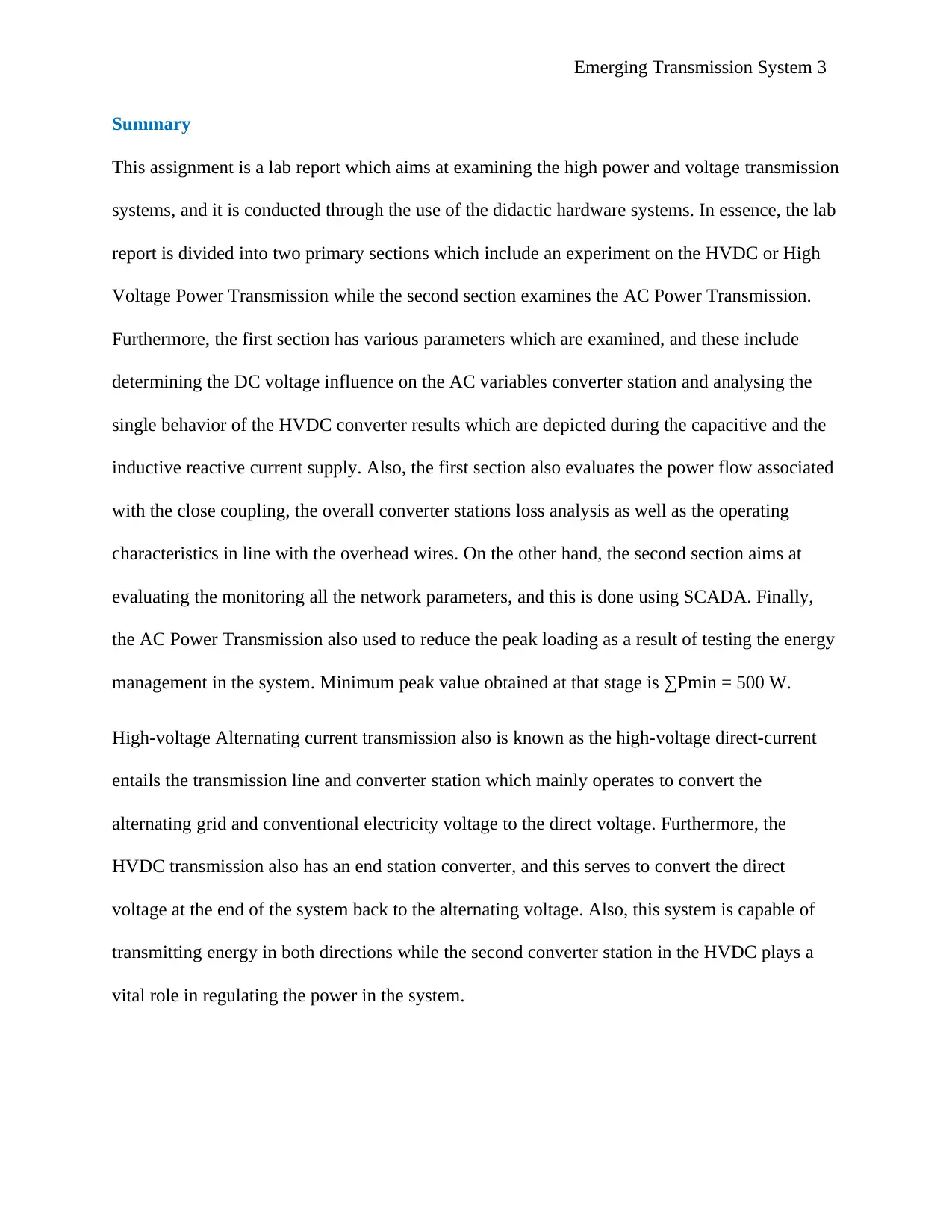
Thus, the diagram below shows a setup experiment which can be used to conduct a High-voltage
Alternating current analysis and illustration is marked as figure 1
Research background
Mostly, electrical power is distributed to the end-users once it has been generated and the
distribution is done via a transmission system to different located sites. The electric power
consumers are broadly divided into categories which include the commercial establishments and
the domestic acts [1] .Thus, the transmission lines will carry the power from the various
substations to the designated consumers in the long run. High-voltage Alternating current
(HVAC) is often suitable for shorter and medium distance transmissions of power whereas the
High voltage Direct Current also known as HVDC mainly operates for the long-distance
transmission. In addition, the HVAC is more economical when dealing with short distance and
have imminent disadvantages on long distances thus, making HVDC suitable for long distance
transmissions [2] .Hence, the theoretical research section for this lab report mainly discussed in
the subsequent sections as follows
High-voltage Alternating current Experiments
High-voltage Alternating current transmission also is known as the high-voltage direct-current
entails the transmission line and converter station which mainly operates to convert the
alternating grid and conventional electricity voltage to the direct voltage. Furthermore, the High-
voltage Alternating current transmission also has an end station converter, and this serves to
convert the direct voltage at the end of the system back to the alternating voltage [3]. Also, this
system is capable of transmitting energy in both directions while the second converter station in
the High-voltage Alternating current plays a vital role in regulating the power in the system.
Thus, the diagram below shows a setup experiment which can be used to conduct a High-voltage
Alternating current analysis and illustration is marked as figure 1
Paraphrase This Document
Need a fresh take? Get an instant paraphrase of this document with our AI Paraphraser
Emerging Transmission System 5
Figure 1: HVDC Experimental Set-Up
High-voltage Alternating current Technologies
This technology uses two converters at the two terminal stations where one station is marked as
U1 and the other station as U2. The U1 represents a rectifier while the U2, on the other hand,
represents an inverter provided that the power is being transmitted from the grid to another.
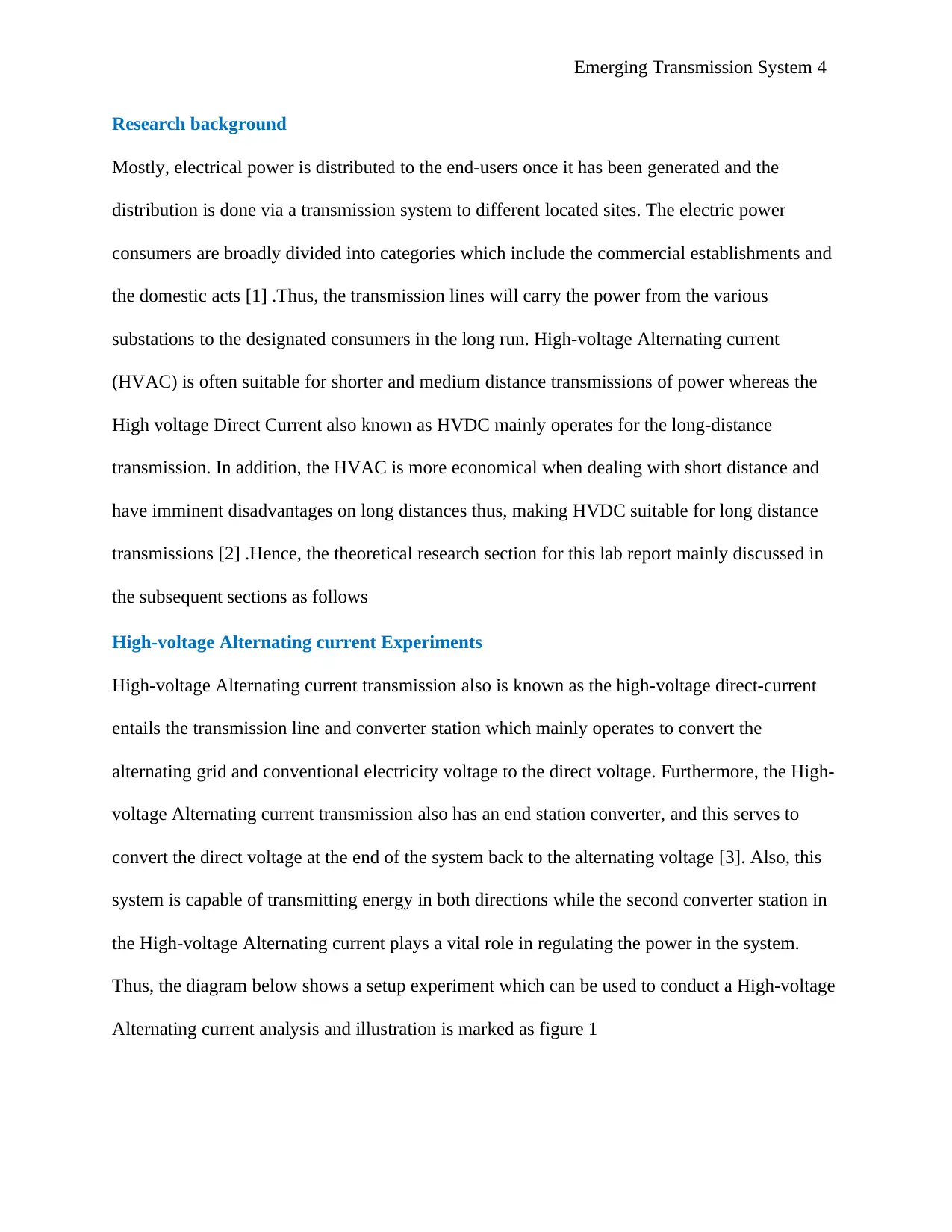
Furthermore, the two transformers are often used in the system, and their presence demarcates
the possibility of having variable voltage ratings in the network. The central facility core is the
conductor with DC, and this can be designed in a manner that it is either a sub-surface cable or
an overhead line [4]. However, the rectified current can exhibits ripples mostly on the chokes
and in the induction cable. There are two key technologies which often used in the recent days
in line with the HVDC transmission, and these technologies are the classic HVDC which involve
the use of line-commutated converter (LCC) and the modern HVDC also known as a voltage-
source converter (VSC). The figure below shows the illustration for the HVDC technologies and
its advanced application in the electric power transmission
Figure 1: HVDC Experimental Set-Up
High-voltage Alternating current Technologies
This technology uses two converters at the two terminal stations where one station is marked as
U1 and the other station as U2. The U1 represents a rectifier while the U2, on the other hand,
represents an inverter provided that the power is being transmitted from the grid to another.
Furthermore, the two transformers are often used in the system, and their presence demarcates
the possibility of having variable voltage ratings in the network. The central facility core is the
conductor with DC, and this can be designed in a manner that it is either a sub-surface cable or
an overhead line [4]. However, the rectified current can exhibits ripples mostly on the chokes
and in the induction cable. There are two key technologies which often used in the recent days
in line with the HVDC transmission, and these technologies are the classic HVDC which involve
the use of line-commutated converter (LCC) and the modern HVDC also known as a voltage-
source converter (VSC). The figure below shows the illustration for the HVDC technologies and
its advanced application in the electric power transmission
Emerging Transmission System 6
Figure 2: HVDC Transmission Converter
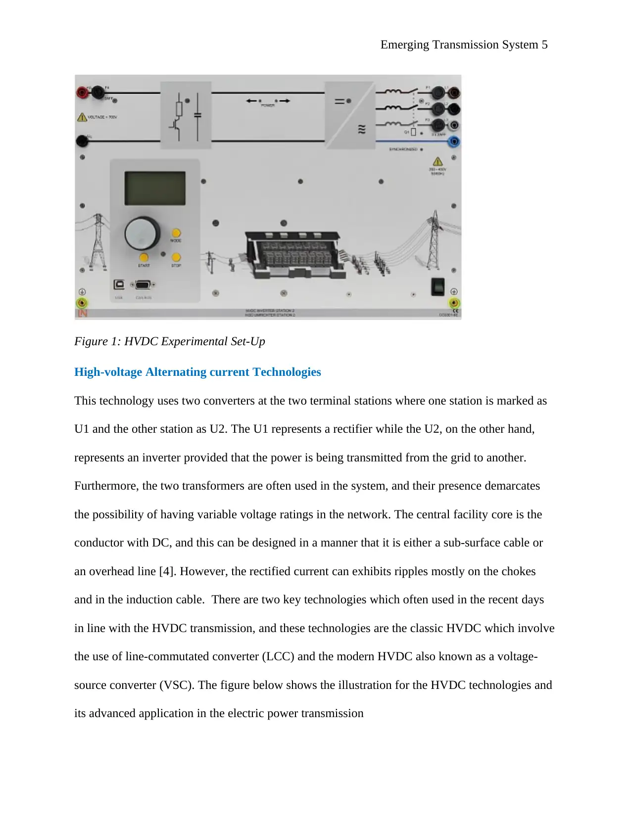
Experimental Methods and Results
The diagram below shows the set up which was used to conduct the experiment
Load Regulation Experiments
This experiment aims at examining the energy management in line with the reduced peak
loading. Before the commencement of this experiment it is essential to evaluate and take note of
these aspects:
1. First, study the analysis of the experimental set up by checking the load regulation as well
as configuring the settings described in it.
Figure 2: HVDC Transmission Converter
Experimental Methods and Results
The diagram below shows the set up which was used to conduct the experiment
Load Regulation Experiments
This experiment aims at examining the energy management in line with the reduced peak
loading. Before the commencement of this experiment it is essential to evaluate and take note of
these aspects:
1. First, study the analysis of the experimental set up by checking the load regulation as well
as configuring the settings described in it.
⊘ This is a preview!⊘
Do you want full access?
Subscribe today to unlock all pages.
Trusted by 1+ million students worldwide
Emerging Transmission System 7
2. Also, take note of the SCADA section by checking the interface along with its standard
setting
3. Thirdly, click the SCADA interface and run it using the Start-Stop and the Switch-on
resistive load located at the left power switch.
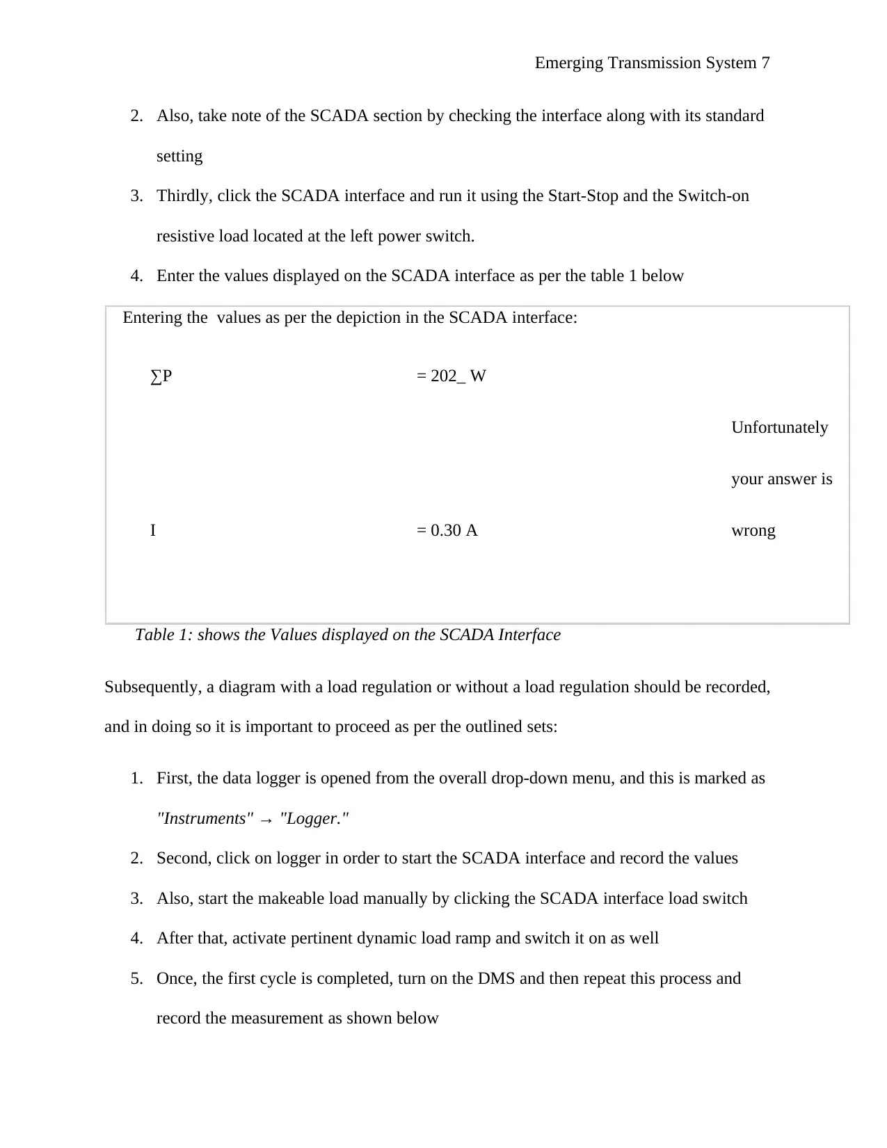
4. Enter the values displayed on the SCADA interface as per the table 1 below
Entering the values as per the depiction in the SCADA interface:
∑P = 202_ W
Unfortunately
I = 0.30 A
your answer is
wrong
Table 1: shows the Values displayed on the SCADA Interface
Subsequently, a diagram with a load regulation or without a load regulation should be recorded,
and in doing so it is important to proceed as per the outlined sets:
1. First, the data logger is opened from the overall drop-down menu, and this is marked as
"Instruments" → "Logger."
2. Second, click on logger in order to start the SCADA interface and record the values
3. Also, start the makeable load manually by clicking the SCADA interface load switch
4. After that, activate pertinent dynamic load ramp and switch it on as well
5. Once, the first cycle is completed, turn on the DMS and then repeat this process and
record the measurement as shown below
2. Also, take note of the SCADA section by checking the interface along with its standard
setting
3. Thirdly, click the SCADA interface and run it using the Start-Stop and the Switch-on
resistive load located at the left power switch.
4. Enter the values displayed on the SCADA interface as per the table 1 below
Entering the values as per the depiction in the SCADA interface:
∑P = 202_ W
Unfortunately
I = 0.30 A
your answer is
wrong
Table 1: shows the Values displayed on the SCADA Interface
Subsequently, a diagram with a load regulation or without a load regulation should be recorded,
and in doing so it is important to proceed as per the outlined sets:
1. First, the data logger is opened from the overall drop-down menu, and this is marked as
"Instruments" → "Logger."
2. Second, click on logger in order to start the SCADA interface and record the values
3. Also, start the makeable load manually by clicking the SCADA interface load switch
4. After that, activate pertinent dynamic load ramp and switch it on as well
5. Once, the first cycle is completed, turn on the DMS and then repeat this process and
record the measurement as shown below
Paraphrase This Document
Need a fresh take? Get an instant paraphrase of this document with our AI Paraphraser
Emerging Transmission System 8
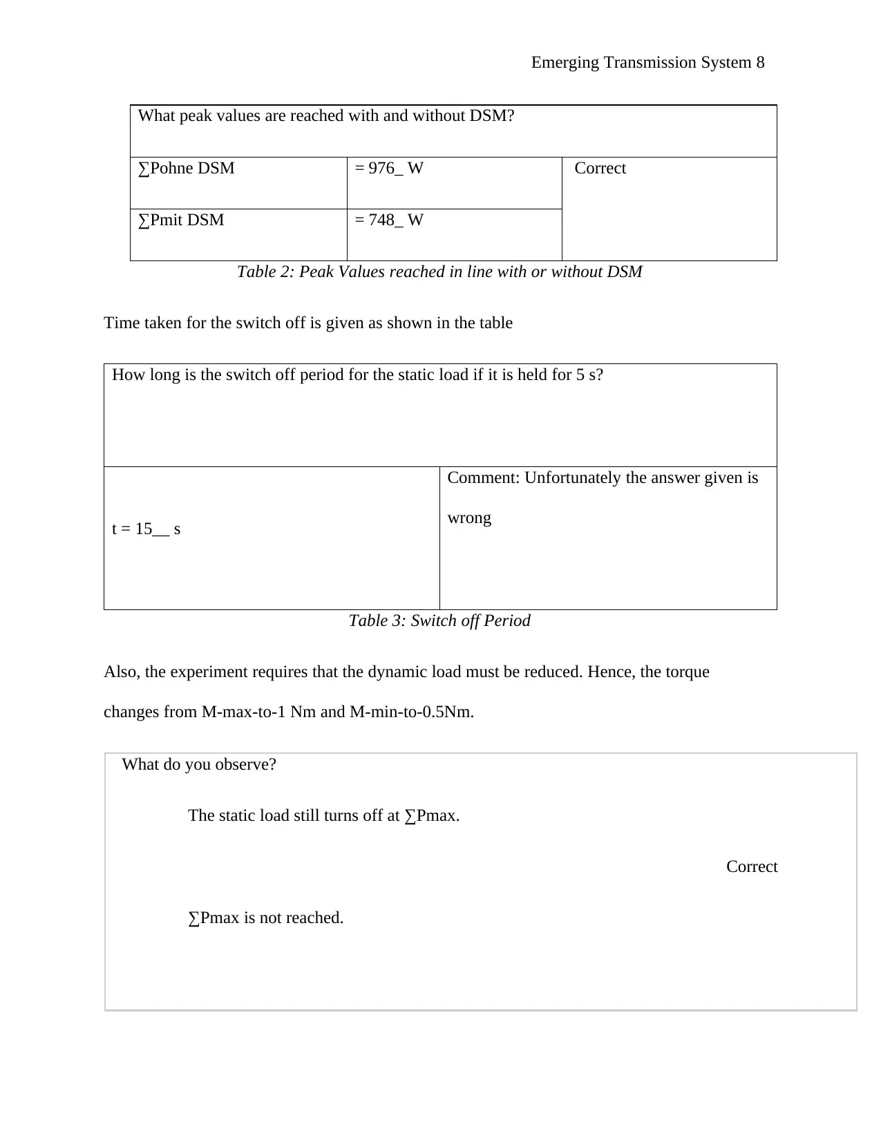
What peak values are reached with and without DSM?
∑Pohne DSM = 976_ W Correct
∑Pmit DSM = 748_ W
Table 2: Peak Values reached in line with or without DSM
Time taken for the switch off is given as shown in the table
How long is the switch off period for the static load if it is held for 5 s?
t = 15__ s
Comment: Unfortunately the answer given is
wrong
Table 3: Switch off Period
Also, the experiment requires that the dynamic load must be reduced. Hence, the torque
changes from M-max-to-1 Nm and M-min-to-0.5Nm.
What do you observe?
The static load still turns off at ∑Pmax.
∑Pmax is not reached.
Correct

Emerging Transmission System 9
Which of the following statements are true?
A. DSM now functions just as it did before.
B. The hysteresis of the DSM system is 0.
C. The static load is continually turned on and off ("it flutters").
Correct
D. DSM still does not affect.
E. ∑Pmin = 500 W
Use the ∑Pmin setting and change ΔP to 100 W.
How does the hysteresis affect the load regulation?
The hysteresis does not affect, and the static load switch is still
"fluttering."
The control system disconnects the load at 500 W and turns
Correct
it back on at 400 W.
⊘ This is a preview!⊘
Do you want full access?
Subscribe today to unlock all pages.
Trusted by 1+ million students worldwide
Emerging Transmission System 10
Operational mode
The pulse-width modulation is usually used to adjust an output voltage ‘s amplitude .The output
voltage can then be adjusted continuously from 0 to the largest possible value. The maximum
amplitude corresponds to the amplitude with the fundamental frequency control.
Below are some of the relevant terms
Switching frequency fs
The switching frequency refers to the frequency at which the power semi-conductor switch. A
switching cycle is usually made of a switch –on operation and a switch –off by the power
semiconductors jointly.
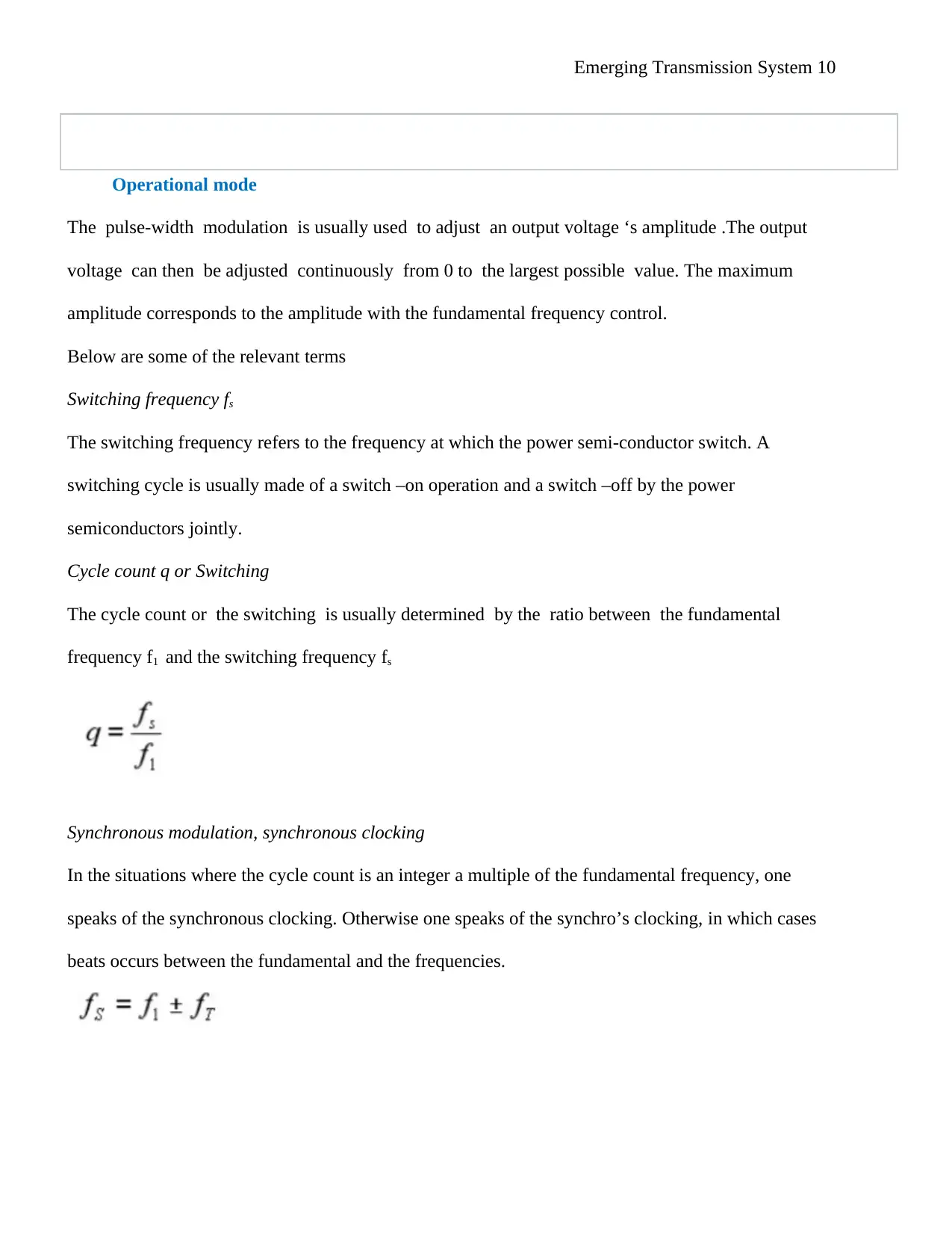
Cycle count q or Switching
The cycle count or the switching is usually determined by the ratio between the fundamental
frequency f1 and the switching frequency fs
Synchronous modulation, synchronous clocking
In the situations where the cycle count is an integer a multiple of the fundamental frequency, one
speaks of the synchronous clocking. Otherwise one speaks of the synchro’s clocking, in which cases
beats occurs between the fundamental and the frequencies.
Operational mode
The pulse-width modulation is usually used to adjust an output voltage ‘s amplitude .The output
voltage can then be adjusted continuously from 0 to the largest possible value. The maximum
amplitude corresponds to the amplitude with the fundamental frequency control.
Below are some of the relevant terms
Switching frequency fs
The switching frequency refers to the frequency at which the power semi-conductor switch. A
switching cycle is usually made of a switch –on operation and a switch –off by the power
semiconductors jointly.
Cycle count q or Switching
The cycle count or the switching is usually determined by the ratio between the fundamental
frequency f1 and the switching frequency fs
Synchronous modulation, synchronous clocking
In the situations where the cycle count is an integer a multiple of the fundamental frequency, one
speaks of the synchronous clocking. Otherwise one speaks of the synchro’s clocking, in which cases
beats occurs between the fundamental and the frequencies.
Paraphrase This Document
Need a fresh take? Get an instant paraphrase of this document with our AI Paraphraser
Emerging Transmission System 11
The beats produces more operating losses, which can be disrupting if the fundamental frequency and
carrier frequency and are located close together. Conversion to synchronous clocking becomes
necessary if ratio fs/f1 is less than 10. At a switching frequency of 1000 Hz this would mean 100 Hz
fundamental frequency [5]
Operation with signal modulation
Experiment aims and objectives
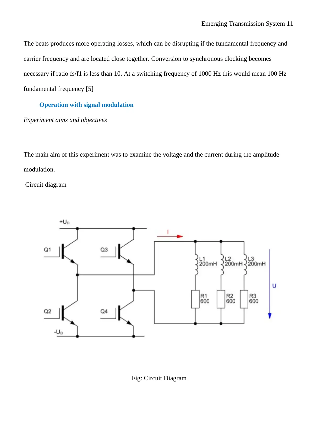
The main aim of this experiment was to examine the voltage and the current during the amplitude
modulation.
Circuit diagram
Fig: Circuit Diagram
The beats produces more operating losses, which can be disrupting if the fundamental frequency and
carrier frequency and are located close together. Conversion to synchronous clocking becomes
necessary if ratio fs/f1 is less than 10. At a switching frequency of 1000 Hz this would mean 100 Hz
fundamental frequency [5]
Operation with signal modulation
Experiment aims and objectives
The main aim of this experiment was to examine the voltage and the current during the amplitude
modulation.
Circuit diagram
Fig: Circuit Diagram
Emerging Transmission System 12
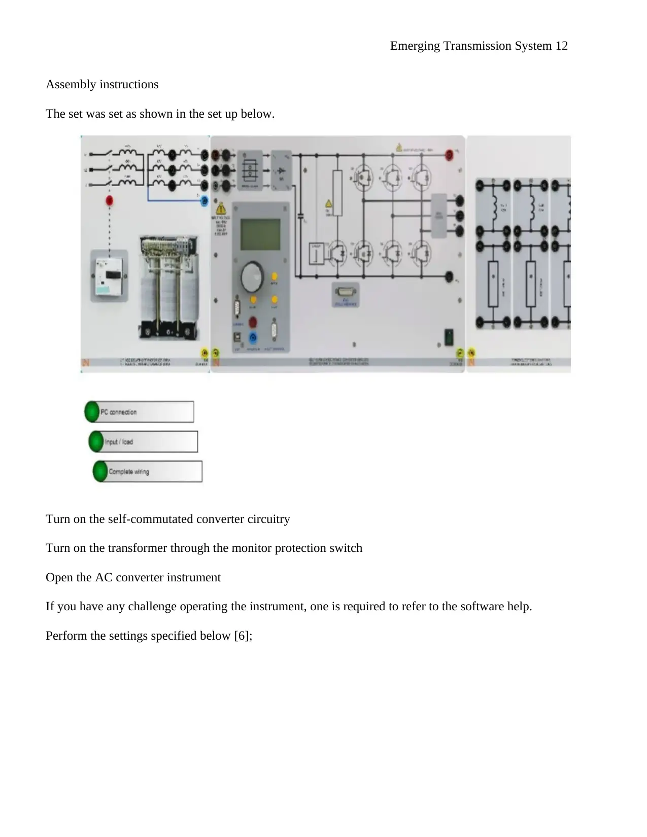
Assembly instructions
The set was set as shown in the set up below.
Turn on the self-commutated converter circuitry
Turn on the transformer through the monitor protection switch
Open the AC converter instrument
If you have any challenge operating the instrument, one is required to refer to the software help.
Perform the settings specified below [6];
⊘ This is a preview!⊘
Do you want full access?
Subscribe today to unlock all pages.
Trusted by 1+ million students worldwide
1 out of 26
Related Documents


Your All-in-One AI-Powered Toolkit for Academic Success.
+13062052269
info@desklib.com
Available 24*7 on WhatsApp / Email
![[object Object]](/_next/static/media/star-bottom.7253800d.svg)
Unlock your academic potential
Copyright © 2020–2025 A2Z Services. All Rights Reserved. Developed and managed by ZUCOL.