ENEM14015 Project: Dynamic System Modeling of Motorbike Suspension
VerifiedAdded on 2020/03/02
|24
|2963
|176
Project
AI Summary
This project report details the development and analysis of a single degree of freedom (SDOF) model for a motorbike suspension system. Conducted as part of the ENEM14015 Dynamic System Modelling and Control course at Central Queensland University, the project utilizes MATLAB to simulate and analyze the performance of the suspension under various conditions. The report begins with an executive summary, followed by an introduction outlining the importance of suspension systems in motorbike performance and safety. It then delves into initial research, including motorbike specifications and the development of mathematical models, progressively simplifying the system to a SDOF representation. The project investigates free vibration, forced vibration, and resonance, calculating damping factors and spring constants. MATLAB simulations are used to visualize system responses, including magnification and transmissibility plots. The report also includes a discussion of instrumentation, specifically accelerometers, and concludes with a comprehensive analysis of the system's behavior under different rider masses and excitation scenarios. The project aims to provide a foundation for further research into more complex motorbike suspension systems.
ENEM14015 Dynamic System Modelling and Control
Project 2: Single Degree of Freedom Systems - T2 2017
Course Co-ordinator: Nur Hassan
Central Queensland University
MKY 1:
S0271157 Ben Bruce
S0257866 Lochlann Crowley
12034473 Kishore Gottipalli
S0258062 Jack McDonald
12059487 Krutarth Dhirubhai Patel
S0154498 Ben Probyn
0
Project 2: Single Degree of Freedom Systems - T2 2017
Course Co-ordinator: Nur Hassan
Central Queensland University
MKY 1:
S0271157 Ben Bruce
S0257866 Lochlann Crowley
12034473 Kishore Gottipalli
S0258062 Jack McDonald
12059487 Krutarth Dhirubhai Patel
S0154498 Ben Probyn
0
Paraphrase This Document
Need a fresh take? Get an instant paraphrase of this document with our AI Paraphraser
Executive Summary
MATLAB models of the suspension of a motorbike using spring and dampers have to be developed
and the developed models have to be analysed so as to understand the performance of the
system. Suitable assumptions have been made to design the system and the performance of the
system under various parameters have been discussed in the report. Calculations have been
carried out to find the damping factors and spring constants of the suspension and the results are
discussed in the report.
Contents
Executive Summary 1
Introduction 2
Initial Research - Motorbike Specifications 2
Mathematical Model 3
Single DOF Free Body Diagram 5
Determining Suspension Values 5
Free Vibration 6
Forced Vibration 9
Resonance System 10
Mathematical Method 11
Magnification and Transmissibility Plots 13
Instrumentation 17
Discussions 20
References: 21
Appendix 22
1
Introduction
The extremities of motorbike sports are possible due to the capabilities of the engine and
suspension systems of their design. The manoeuvrability and power to weight ratio of modern
motorbikes, allows the vehicles to be taken into extreme terrain, all whilst operating within the
capabilities of the system. The dynamic suspension systems used allow for great force to be applied
to the system, whilst maintaining rider comfort and manoeuvrability.
The reliability of the suspension system if relied upon most importantly for safety, however ride
quality and handling are effective completely by the dynamics of the system. The structure
incorporates damping and stiffness, taken near to limits whilst performing intensive tasks, such as
recovering from landing a large jump. For the following report, the motorcycle system has been
simplified to a Single Degree of Freedom System, eliminating a number of realistic factors, such as
the roll and pitch. The simplification of a SDOF diagram will be an effective way to remain realistic
with the development of results, whilst leaving room for the development of further testing at a
later date. The project may be improved in the future with the development of Two Degree of
Freedom systems, as well as analysing further variations of stunts performed on the motorcycle. A
simple approach will allow for a more in depth development of results through modelling. Modelling
performed will be in the nature of free vibration, forced vibration and road surface vibration.
A number of assumptions were made for the purpose of testing, being:
- Rider position on the X axis does not change.
- There is no roll or pitch considered.
- Both front and rear suspension compress and release in unison.
- Tyre flexibility will not be considered.
Overall, the project will be an effective development and starting point, for the research of further
development into motorcycle systems. Results found through testing will be compared, so as to find
bugs in data, and anomalies. The study will conclusively investigate the nature of both free and
forced vibration for the scenario, whilst also investigating more generally operation such as standard
road travel at highway speeds. All testing will consider riders of a range of masses.
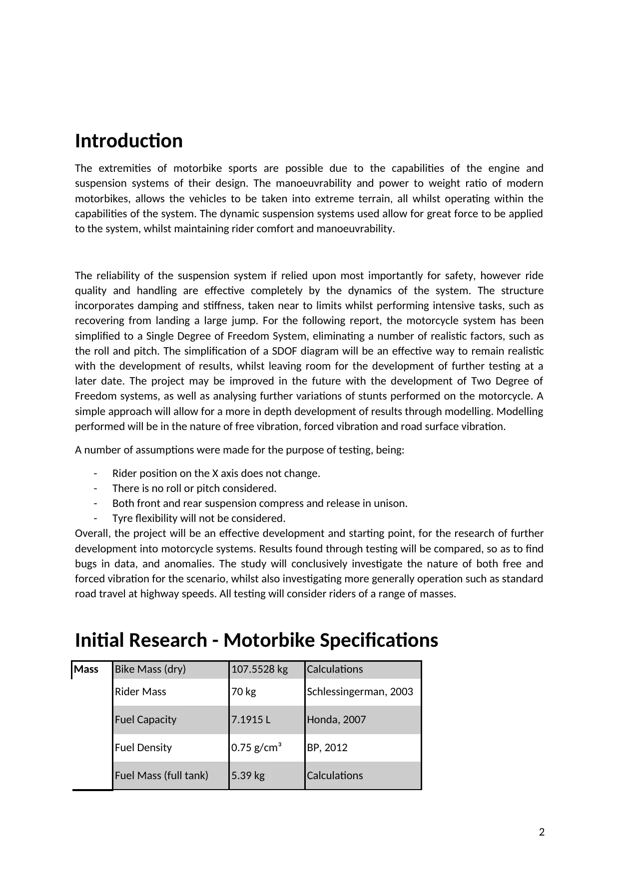
Initial Research - Motorbike Specifications
Mass Bike Mass (dry) 107.5528 kg Calculations
Rider Mass 70 kg Schlessingerman, 2003
Fuel Capacity 7.1915 L Honda, 2007
Fuel Density 0.75 g/cm³ BP, 2012
Fuel Mass (full tank) 5.39 kg Calculations
2
The extremities of motorbike sports are possible due to the capabilities of the engine and
suspension systems of their design. The manoeuvrability and power to weight ratio of modern
motorbikes, allows the vehicles to be taken into extreme terrain, all whilst operating within the
capabilities of the system. The dynamic suspension systems used allow for great force to be applied
to the system, whilst maintaining rider comfort and manoeuvrability.
The reliability of the suspension system if relied upon most importantly for safety, however ride
quality and handling are effective completely by the dynamics of the system. The structure
incorporates damping and stiffness, taken near to limits whilst performing intensive tasks, such as
recovering from landing a large jump. For the following report, the motorcycle system has been
simplified to a Single Degree of Freedom System, eliminating a number of realistic factors, such as
the roll and pitch. The simplification of a SDOF diagram will be an effective way to remain realistic
with the development of results, whilst leaving room for the development of further testing at a
later date. The project may be improved in the future with the development of Two Degree of
Freedom systems, as well as analysing further variations of stunts performed on the motorcycle. A
simple approach will allow for a more in depth development of results through modelling. Modelling
performed will be in the nature of free vibration, forced vibration and road surface vibration.
A number of assumptions were made for the purpose of testing, being:
- Rider position on the X axis does not change.
- There is no roll or pitch considered.
- Both front and rear suspension compress and release in unison.
- Tyre flexibility will not be considered.
Overall, the project will be an effective development and starting point, for the research of further
development into motorcycle systems. Results found through testing will be compared, so as to find
bugs in data, and anomalies. The study will conclusively investigate the nature of both free and
forced vibration for the scenario, whilst also investigating more generally operation such as standard
road travel at highway speeds. All testing will consider riders of a range of masses.
Initial Research - Motorbike Specifications
Mass Bike Mass (dry) 107.5528 kg Calculations
Rider Mass 70 kg Schlessingerman, 2003
Fuel Capacity 7.1915 L Honda, 2007
Fuel Density 0.75 g/cm³ BP, 2012
Fuel Mass (full tank) 5.39 kg Calculations
2
⊘ This is a preview!⊘
Do you want full access?
Subscribe today to unlock all pages.
Trusted by 1+ million students worldwide
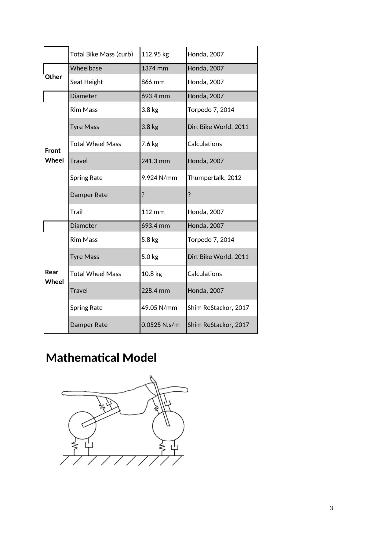
Total Bike Mass (curb) 112.95 kg Honda, 2007
Other
Wheelbase 1374 mm Honda, 2007
Seat Height 866 mm Honda, 2007
Front
Wheel
Diameter 693.4 mm Honda, 2007
Rim Mass 3.8 kg Torpedo 7, 2014
Tyre Mass 3.8 kg Dirt Bike World, 2011
Total Wheel Mass 7.6 kg Calculations
Travel 241.3 mm Honda, 2007
Spring Rate 9.924 N/mm Thumpertalk, 2012
Damper Rate ? ?
Trail 112 mm Honda, 2007
Rear
Wheel
Diameter 693.4 mm Honda, 2007
Rim Mass 5.8 kg Torpedo 7, 2014
Tyre Mass 5.0 kg Dirt Bike World, 2011
Total Wheel Mass 10.8 kg Calculations
Travel 228.4 mm Honda, 2007
Spring Rate 49.05 N/mm Shim ReStackor, 2017
Damper Rate 0.0525 N.s/m Shim ReStackor, 2017
Mathematical Model
3
Paraphrase This Document
Need a fresh take? Get an instant paraphrase of this document with our AI Paraphraser
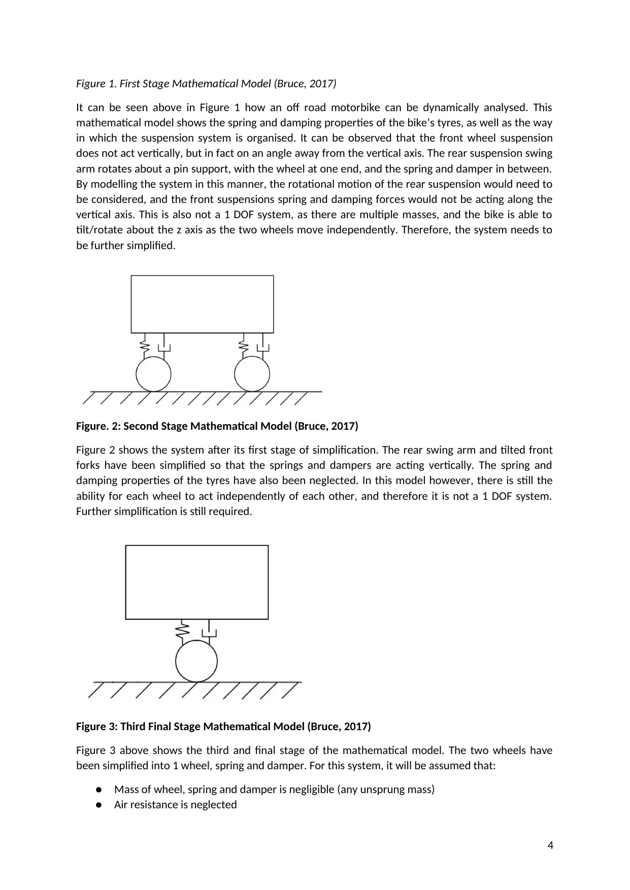
Figure 1. First Stage Mathematical Model (Bruce, 2017)
It can be seen above in Figure 1 how an off road motorbike can be dynamically analysed. This
mathematical model shows the spring and damping properties of the bike’s tyres, as well as the way
in which the suspension system is organised. It can be observed that the front wheel suspension
does not act vertically, but in fact on an angle away from the vertical axis. The rear suspension swing
arm rotates about a pin support, with the wheel at one end, and the spring and damper in between.
By modelling the system in this manner, the rotational motion of the rear suspension would need to
be considered, and the front suspensions spring and damping forces would not be acting along the
vertical axis. This is also not a 1 DOF system, as there are multiple masses, and the bike is able to
tilt/rotate about the z axis as the two wheels move independently. Therefore, the system needs to
be further simplified.
Figure. 2: Second Stage Mathematical Model (Bruce, 2017)
Figure 2 shows the system after its first stage of simplification. The rear swing arm and tilted front
forks have been simplified so that the springs and dampers are acting vertically. The spring and
damping properties of the tyres have also been neglected. In this model however, there is still the
ability for each wheel to act independently of each other, and therefore it is not a 1 DOF system.
Further simplification is still required.
Figure 3: Third Final Stage Mathematical Model (Bruce, 2017)
Figure 3 above shows the third and final stage of the mathematical model. The two wheels have
been simplified into 1 wheel, spring and damper. For this system, it will be assumed that:
● Mass of wheel, spring and damper is negligible (any unsprung mass)
● Air resistance is neglected
4
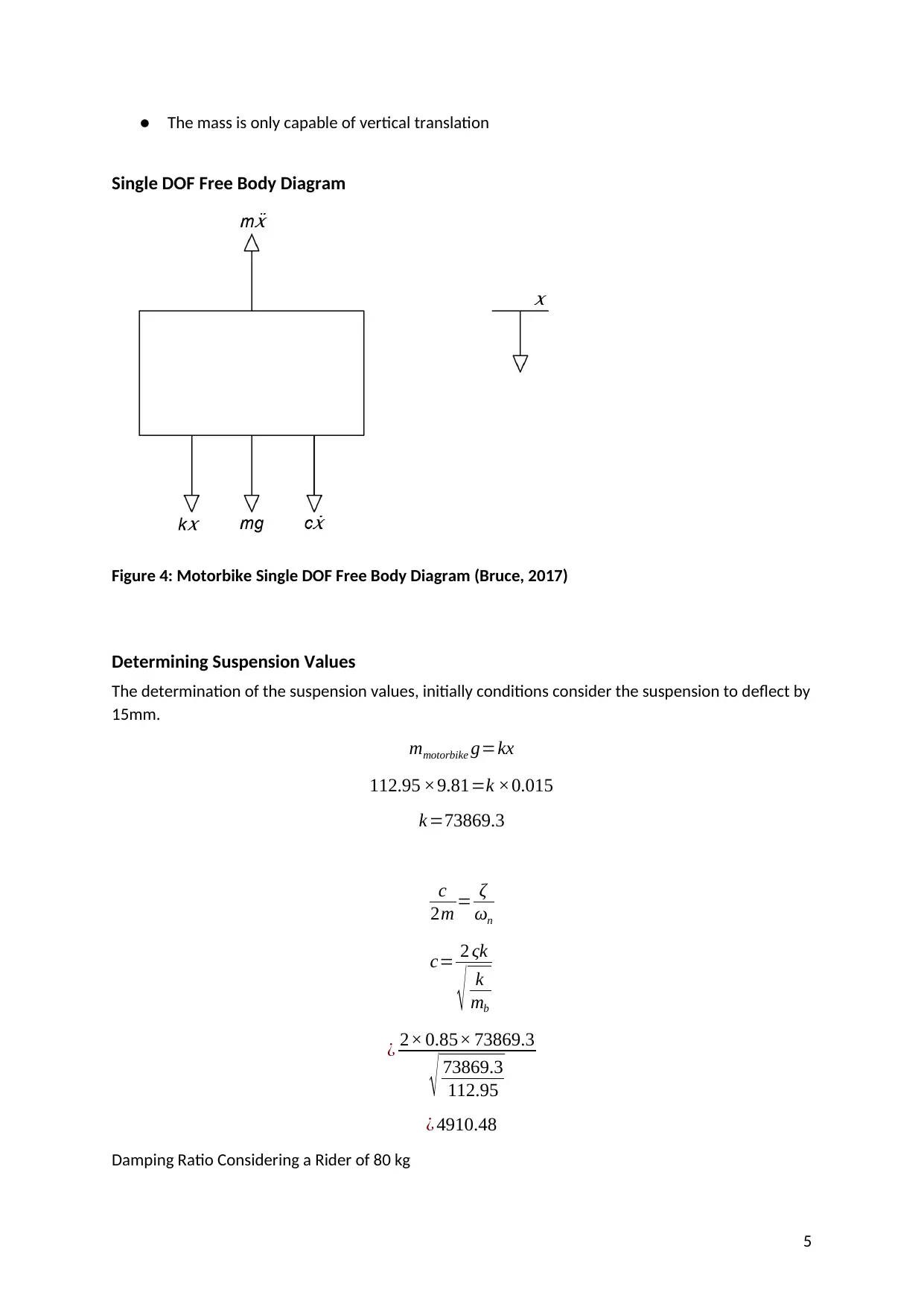
● The mass is only capable of vertical translation
Single DOF Free Body Diagram
Figure 4: Motorbike Single DOF Free Body Diagram (Bruce, 2017)
Determining Suspension Values
The determination of the suspension values, initially conditions consider the suspension to deflect by
15mm.
mmotorbike g=kx
112.95 ×9.81=k ×0.015
k =73869.3
c
2m = ζ
ωn
c= 2 ςk
√ k
mb
¿ 2× 0.85× 73869.3
√ 73869.3
112.95
¿ 4910.48
Damping Ratio Considering a Rider of 80 kg
5
⊘ This is a preview!⊘
Do you want full access?
Subscribe today to unlock all pages.
Trusted by 1+ million students worldwide
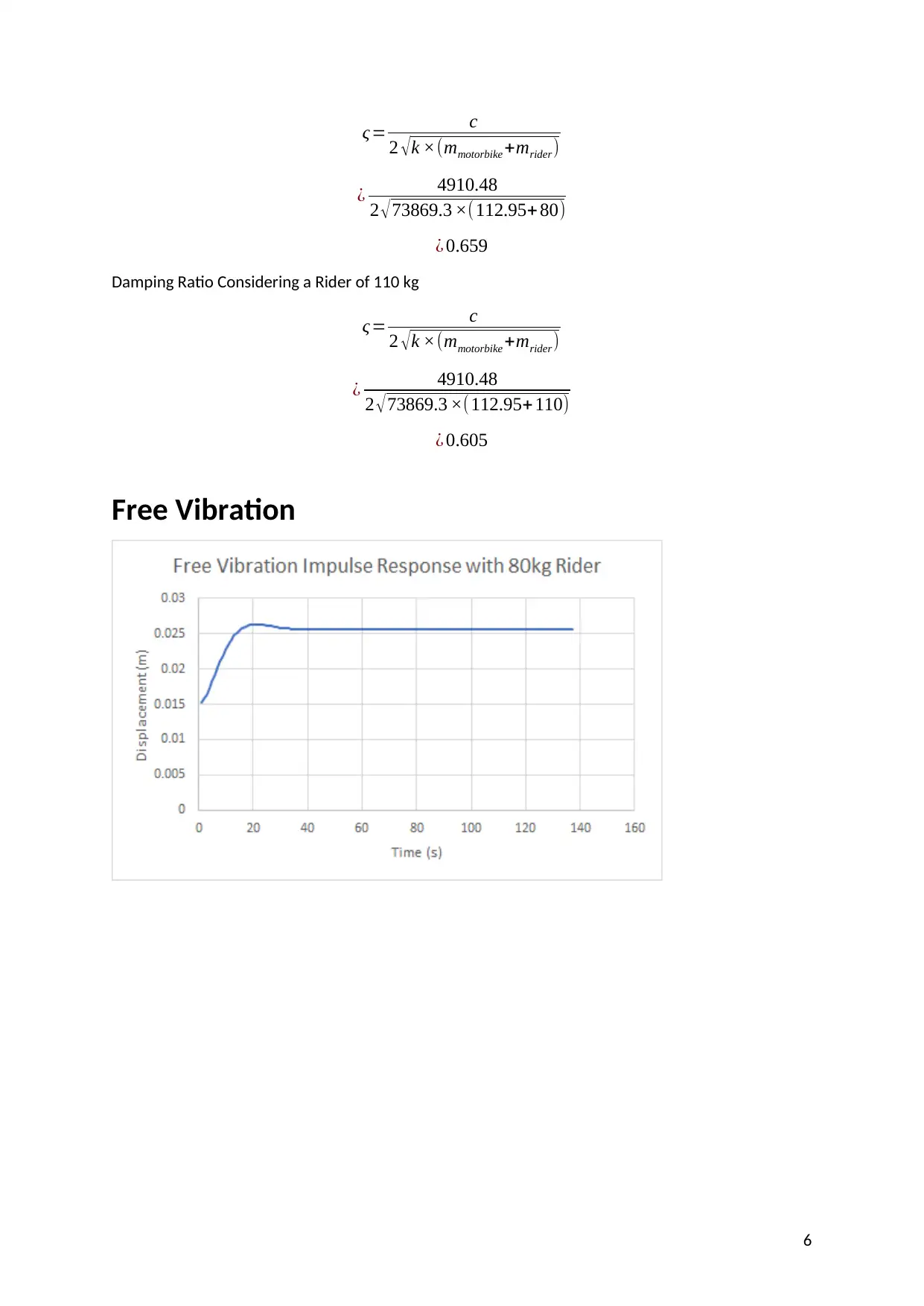
ς= c
2 √k ×(mmotorbike +mrider)
¿ 4910.48
2 √73869.3 ×(112.95+ 80)
¿ 0.659
Damping Ratio Considering a Rider of 110 kg
ς= c
2 √k ×(mmotorbike +mrider)
¿ 4910.48
2 √73869.3 ×(112.95+110)
¿ 0.605
Free Vibration
6
2 √k ×(mmotorbike +mrider)
¿ 4910.48
2 √73869.3 ×(112.95+ 80)
¿ 0.659
Damping Ratio Considering a Rider of 110 kg
ς= c
2 √k ×(mmotorbike +mrider)
¿ 4910.48
2 √73869.3 ×(112.95+110)
¿ 0.605
Free Vibration
6
Paraphrase This Document
Need a fresh take? Get an instant paraphrase of this document with our AI Paraphraser
7
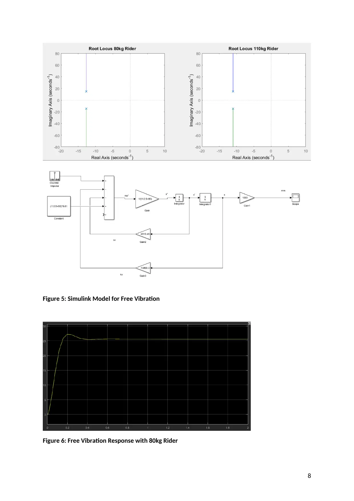
Figure 5: Simulink Model for Free Vibration
Figure 6: Free Vibration Response with 80kg Rider
8
Figure 6: Free Vibration Response with 80kg Rider
8
⊘ This is a preview!⊘
Do you want full access?
Subscribe today to unlock all pages.
Trusted by 1+ million students worldwide
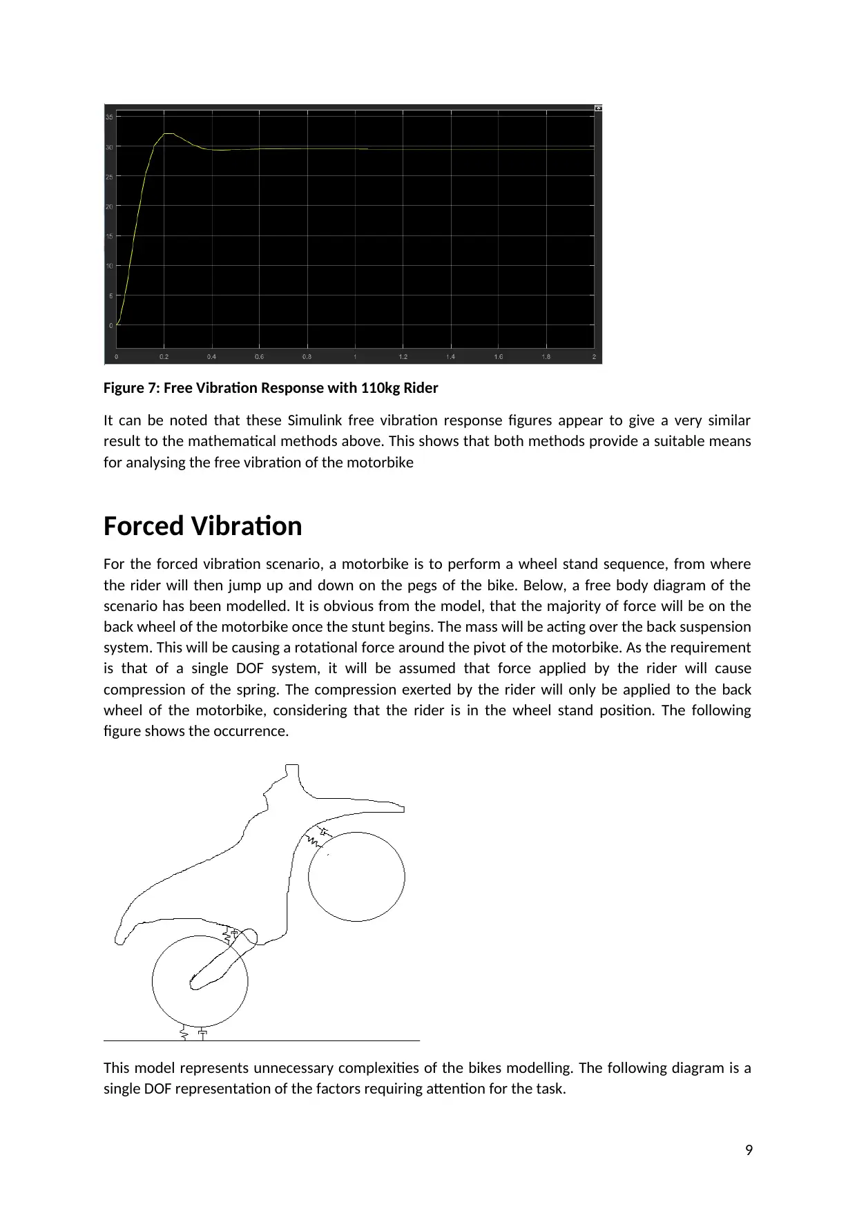
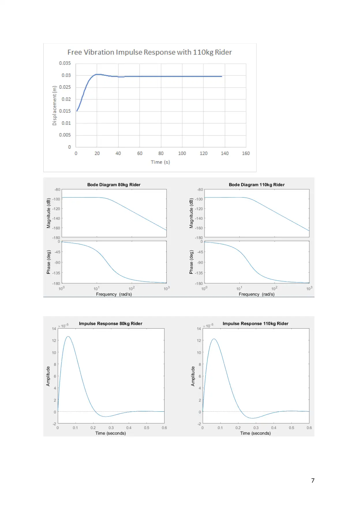
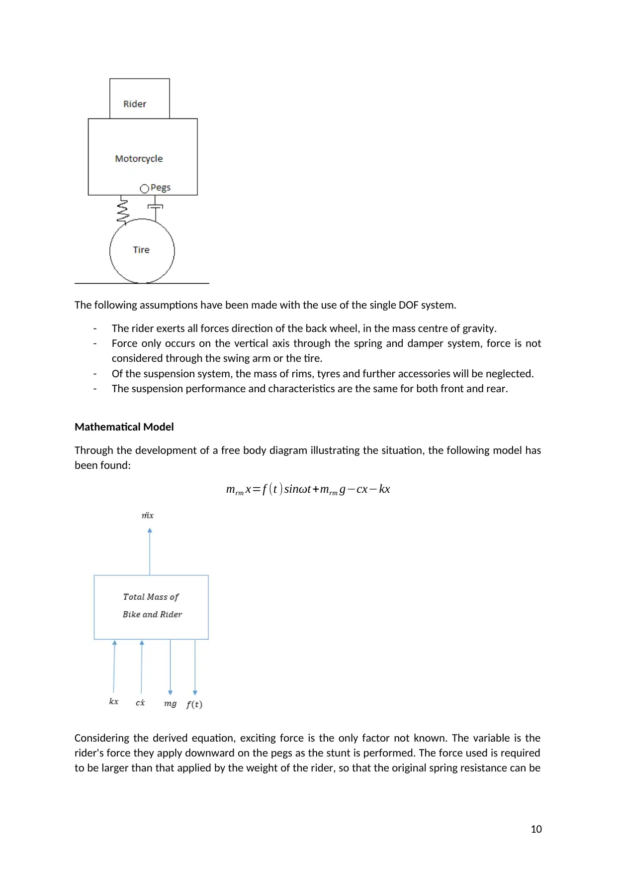
Figure 7: Free Vibration Response with 110kg Rider
It can be noted that these Simulink free vibration response figures appear to give a very similar
result to the mathematical methods above. This shows that both methods provide a suitable means
for analysing the free vibration of the motorbike
Forced Vibration
For the forced vibration scenario, a motorbike is to perform a wheel stand sequence, from where
the rider will then jump up and down on the pegs of the bike. Below, a free body diagram of the
scenario has been modelled. It is obvious from the model, that the majority of force will be on the
back wheel of the motorbike once the stunt begins. The mass will be acting over the back suspension
system. This will be causing a rotational force around the pivot of the motorbike. As the requirement
is that of a single DOF system, it will be assumed that force applied by the rider will cause
compression of the spring. The compression exerted by the rider will only be applied to the back
wheel of the motorbike, considering that the rider is in the wheel stand position. The following
figure shows the occurrence.
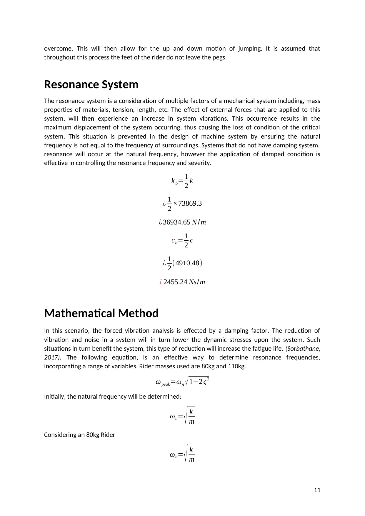
This model represents unnecessary complexities of the bikes modelling. The following diagram is a
single DOF representation of the factors requiring attention for the task.
9
It can be noted that these Simulink free vibration response figures appear to give a very similar
result to the mathematical methods above. This shows that both methods provide a suitable means
for analysing the free vibration of the motorbike
Forced Vibration
For the forced vibration scenario, a motorbike is to perform a wheel stand sequence, from where
the rider will then jump up and down on the pegs of the bike. Below, a free body diagram of the
scenario has been modelled. It is obvious from the model, that the majority of force will be on the
back wheel of the motorbike once the stunt begins. The mass will be acting over the back suspension
system. This will be causing a rotational force around the pivot of the motorbike. As the requirement
is that of a single DOF system, it will be assumed that force applied by the rider will cause
compression of the spring. The compression exerted by the rider will only be applied to the back
wheel of the motorbike, considering that the rider is in the wheel stand position. The following
figure shows the occurrence.
This model represents unnecessary complexities of the bikes modelling. The following diagram is a
single DOF representation of the factors requiring attention for the task.
9
Paraphrase This Document
Need a fresh take? Get an instant paraphrase of this document with our AI Paraphraser
The following assumptions have been made with the use of the single DOF system.
- The rider exerts all forces direction of the back wheel, in the mass centre of gravity.
- Force only occurs on the vertical axis through the spring and damper system, force is not
considered through the swing arm or the tire.
- Of the suspension system, the mass of rims, tyres and further accessories will be neglected.
- The suspension performance and characteristics are the same for both front and rear.
Mathematical Model
Through the development of a free body diagram illustrating the situation, the following model has
been found:
mrm x=f (t )sinωt +mrm g−cx−kx
Considering the derived equation, exciting force is the only factor not known. The variable is the
rider's force they apply downward on the pegs as the stunt is performed. The force used is required
to be larger than that applied by the weight of the rider, so that the original spring resistance can be
10
overcome. This will then allow for the up and down motion of jumping. It is assumed that
throughout this process the feet of the rider do not leave the pegs.
Resonance System
The resonance system is a consideration of multiple factors of a mechanical system including, mass
properties of materials, tension, length, etc. The effect of external forces that are applied to this
system, will then experience an increase in system vibrations. This occurrence results in the
maximum displacement of the system occurring, thus causing the loss of condition of the critical
system. This situation is prevented in the design of machine system by ensuring the natural
frequency is not equal to the frequency of surroundings. Systems that do not have damping system,
resonance will occur at the natural frequency, however the application of damped condition is
effective in controlling the resonance frequency and severity.
k b= 1
2 k
¿ 1
2 ×73869.3
¿ 36934.65 N /m
cb= 1
2 c
¿ 1
2 ( 4910.48)
¿ 2455.24 Ns/m
Mathematical Method
In this scenario, the forced vibration analysis is effected by a damping factor. The reduction of
vibration and noise in a system will in turn lower the dynamic stresses upon the system. Such
situations in turn benefit the system, this type of reduction will increase the fatigue life. (Sorbathane,
2017). The following equation, is an effective way to determine resonance frequencies,
incorporating a range of variables. Rider masses used are 80kg and 110kg.
ω peak =ωn √ 1−2 ς2
Initially, the natural frequency will be determined:
ωn= √ k
m
Considering an 80kg Rider
ωn= √ k
m
11
⊘ This is a preview!⊘
Do you want full access?
Subscribe today to unlock all pages.
Trusted by 1+ million students worldwide
1 out of 24