Ask a question from expert

Ask now

ENEM14015 - Dynamic System Modelling and Control

24 Pages2963 Words176 Views
   

CQUniversity Australia


Dynamic System Modelling and Control (ENEM14015)


Added on  2020-03-02

About This Document

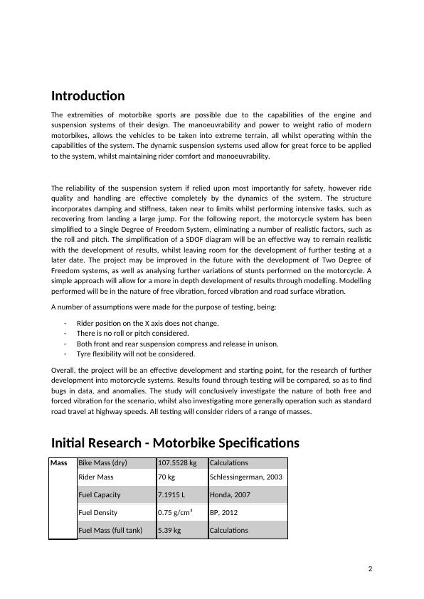
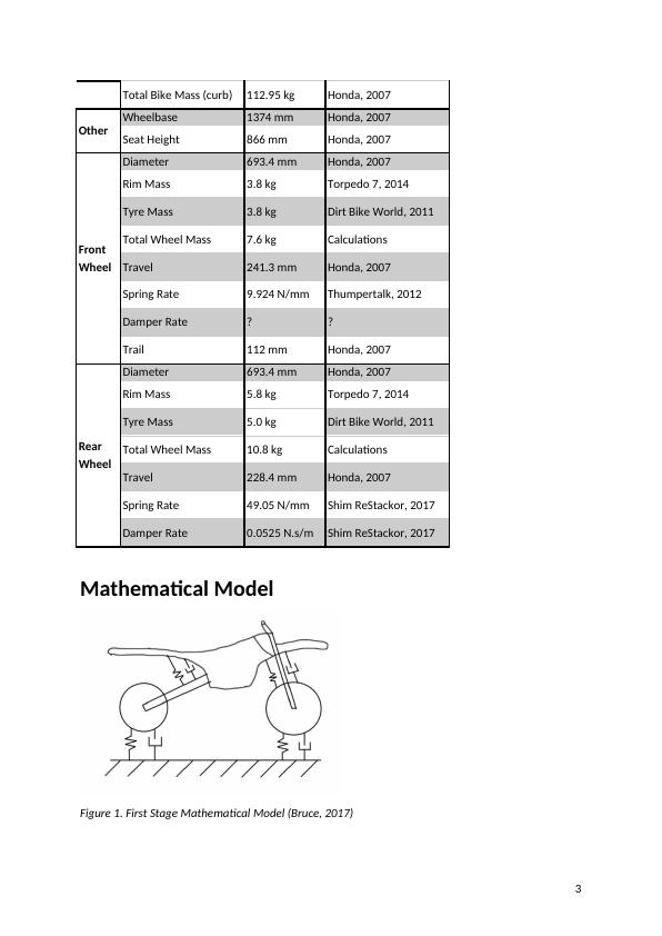
In this document, we will discuss models of the suspension of a motorbike using spring and dampers which have to be developed and the business models have to be analyzed to understand the performance of the system. Also, we cover the Suitable assumptions which have been made to design the system and the performance of the system under various parameters. Calculations have been carried out to find the damping factors and spring constants of the suspension and the results.

ENEM14015 - Dynamic System Modelling and Control


CQUniversity Australia


Dynamic System Modelling and Control (ENEM14015)

   Added on 2020-03-02

BookmarkShareRelated Documents
ENEM14015 Dynamic System Modelling and ControlProject 2: Single Degree of Freedom Systems - T2 2017Course Co-ordinator: Nur HassanCentral Queensland UniversityMKY 1:S0271157 Ben BruceS0257866 Lochlann Crowley12034473 Kishore GottipalliS0258062 Jack McDonald12059487 Krutarth Dhirubhai PatelS0154498 Ben Probyn0
ENEM14015 - Dynamic System Modelling and Control_1
Executive SummaryMATLAB models of the suspension of a motorbike using spring and dampers have to be developedand the developed models have to be analysed so as to understand the performance of thesystem. Suitable assumptions have been made to design the system and the performance of thesystem under various parameters have been discussed in the report. Calculations have beencarried out to find the damping factors and spring constants of the suspension and the results arediscussed in the report.ContentsExecutive Summary1Introduction2Initial Research - Motorbike Specifications2Mathematical Model3Single DOF Free Body Diagram5Determining Suspension Values5Free Vibration6Forced Vibration9Resonance System10Mathematical Method 11Magnification and Transmissibility Plots 13Instrumentation 17Discussions20References:21Appendix221
ENEM14015 - Dynamic System Modelling and Control_2
IntroductionThe extremities of motorbike sports are possible due to the capabilities of the engine andsuspension systems of their design. The manoeuvrability and power to weight ratio of modernmotorbikes, allows the vehicles to be taken into extreme terrain, all whilst operating within thecapabilities of the system. The dynamic suspension systems used allow for great force to be appliedto the system, whilst maintaining rider comfort and manoeuvrability.The reliability of the suspension system if relied upon most importantly for safety, however ridequality and handling are effective completely by the dynamics of the system. The structureincorporates damping and stiffness, taken near to limits whilst performing intensive tasks, such asrecovering from landing a large jump. For the following report, the motorcycle system has beensimplified to a Single Degree of Freedom System, eliminating a number of realistic factors, such asthe roll and pitch. The simplification of a SDOF diagram will be an effective way to remain realisticwith the development of results, whilst leaving room for the development of further testing at alater date. The project may be improved in the future with the development of Two Degree ofFreedom systems, as well as analysing further variations of stunts performed on the motorcycle. Asimple approach will allow for a more in depth development of results through modelling. Modellingperformed will be in the nature of free vibration, forced vibration and road surface vibration.A number of assumptions were made for the purpose of testing, being:-Rider position on the X axis does not change.-There is no roll or pitch considered.-Both front and rear suspension compress and release in unison. -Tyre flexibility will not be considered.Overall, the project will be an effective development and starting point, for the research of furtherdevelopment into motorcycle systems. Results found through testing will be compared, so as to findbugs in data, and anomalies. The study will conclusively investigate the nature of both free andforced vibration for the scenario, whilst also investigating more generally operation such as standardroad travel at highway speeds. All testing will consider riders of a range of masses. Initial Research - Motorbike SpecificationsMassBike Mass (dry)107.5528 kgCalculationsRider Mass70 kgSchlessingerman, 2003Fuel Capacity7.1915 LHonda, 2007Fuel Density0.75 g/cm³BP, 2012Fuel Mass (full tank)5.39 kgCalculations2
ENEM14015 - Dynamic System Modelling and Control_3
Total Bike Mass (curb)112.95 kgHonda, 2007OtherWheelbase1374 mmHonda, 2007Seat Height866 mmHonda, 2007FrontWheelDiameter693.4 mmHonda, 2007Rim Mass3.8 kgTorpedo 7, 2014Tyre Mass3.8 kgDirt Bike World, 2011Total Wheel Mass7.6 kgCalculationsTravel241.3 mmHonda, 2007Spring Rate9.924 N/mmThumpertalk, 2012Damper Rate??Trail112 mmHonda, 2007RearWheelDiameter693.4 mmHonda, 2007Rim Mass5.8 kgTorpedo 7, 2014Tyre Mass5.0 kgDirt Bike World, 2011Total Wheel Mass10.8 kgCalculationsTravel228.4 mmHonda, 2007Spring Rate49.05 N/mmShim ReStackor, 2017Damper Rate0.0525 N.s/mShim ReStackor, 2017Mathematical ModelFigure 1. First Stage Mathematical Model (Bruce, 2017)3
ENEM14015 - Dynamic System Modelling and Control_4
It can be seen above in Figure 1 how an off road motorbike can be dynamically analysed. Thismathematical model shows the spring and damping properties of the bike’s tyres, as well as the wayin which the suspension system is organised. It can be observed that the front wheel suspensiondoes not act vertically, but in fact on an angle away from the vertical axis. The rear suspension swingarm rotates about a pin support, with the wheel at one end, and the spring and damper in between.By modelling the system in this manner, the rotational motion of the rear suspension would need tobe considered, and the front suspensions spring and damping forces would not be acting along thevertical axis. This is also not a 1 DOF system, as there are multiple masses, and the bike is able to tilt/rotate about the z axis as the two wheels move independently. Therefore, the system needs to befurther simplified.Figure. 2: Second Stage Mathematical Model (Bruce, 2017)Figure 2 shows the system after its first stage of simplification. The rear swing arm and tilted frontforks have been simplified so that the springs and dampers are acting vertically. The spring anddamping properties of the tyres have also been neglected. In this model however, there is still theability for each wheel to act independently of each other, and therefore it is not a 1 DOF system.Further simplification is still required.Figure 3: Third Final Stage Mathematical Model (Bruce, 2017)Figure 3 above shows the third and final stage of the mathematical model. The two wheels havebeen simplified into 1 wheel, spring and damper. For this system, it will be assumed that:Mass of wheel, spring and damper is negligible (any unsprung mass)Air resistance is neglectedThe mass is only capable of vertical translation4
ENEM14015 - Dynamic System Modelling and Control_5
Single DOF Free Body DiagramFigure 4: Motorbike Single DOF Free Body Diagram (Bruce, 2017)Determining Suspension ValuesThe determination of the suspension values, initially conditions consider the suspension to deflect by15mm.mmotorbikeg=kx112.95×9.81=k×0.015k=73869.3c2m=ζωnc=2ςkkmb¿2×0.85×73869.373869.3112.95¿4910.48Damping Ratio Considering a Rider of 80 kgς=c2k×(mmotorbike+mrider)5
ENEM14015 - Dynamic System Modelling and Control_6

End of preview

Want to access all the pages? Upload your documents or become a member.

Related Documents
AMME3500 SYSTEMS DYNAMICS AND CONTROL.
|20
|3316
|1

MECH3422 - Dynamic System Modelling and Control
|10
|1352
|258

Dynamic System Modelling of a Motor Bike
|17
|2333
|216

Advanced Modeling, Simulation and Control of Dynamic Systems
|38
|4663
|338

Magnification Factor and DOF simulation- Project
|25
|3505
|357

ENEV 372 - Dynamic System Modelling and Control
|7
|1068
|146