Engineering Design Report: CAD Software, Features, and Benefits
VerifiedAdded on 2023/05/28
|13
|1530
|308
Report
AI Summary
This report, prepared by a student, provides a comprehensive overview of Computer-Aided Design (CAD) and its applications in engineering. The report begins with an introduction to CAD, highlighting its benefits such as improved design quality, enhanced communication, and increased productivity. It then delves into the selection of CAD software, focusing on 2D and 3D options like AutoCAD and SolidWorks, providing examples of their use in creating sketches, engineering drawings, 3D models, and simulations. The report outlines the key features of CAD systems, including standard layouts, parts and components libraries, engineering calculations (like center of gravity and costing), finite element analysis, material selection, circuit layouts (hydraulic and electrical), circuit analysis, logic simulation, and bill of materials. Furthermore, the report specifies the required computer software and hardware for presenting CAD drawings to a commercially acceptable standard and provides calculations for the cost per CAD seat, including software, workstation, and maintenance costs. Finally, it analyzes the compatibility of the selected CAD software with other companies' software and assesses how CAD benefits other departments within a manufacturing company, emphasizing improved communication and reduced error margins. The report concludes with a list of cited references.
Page | 1
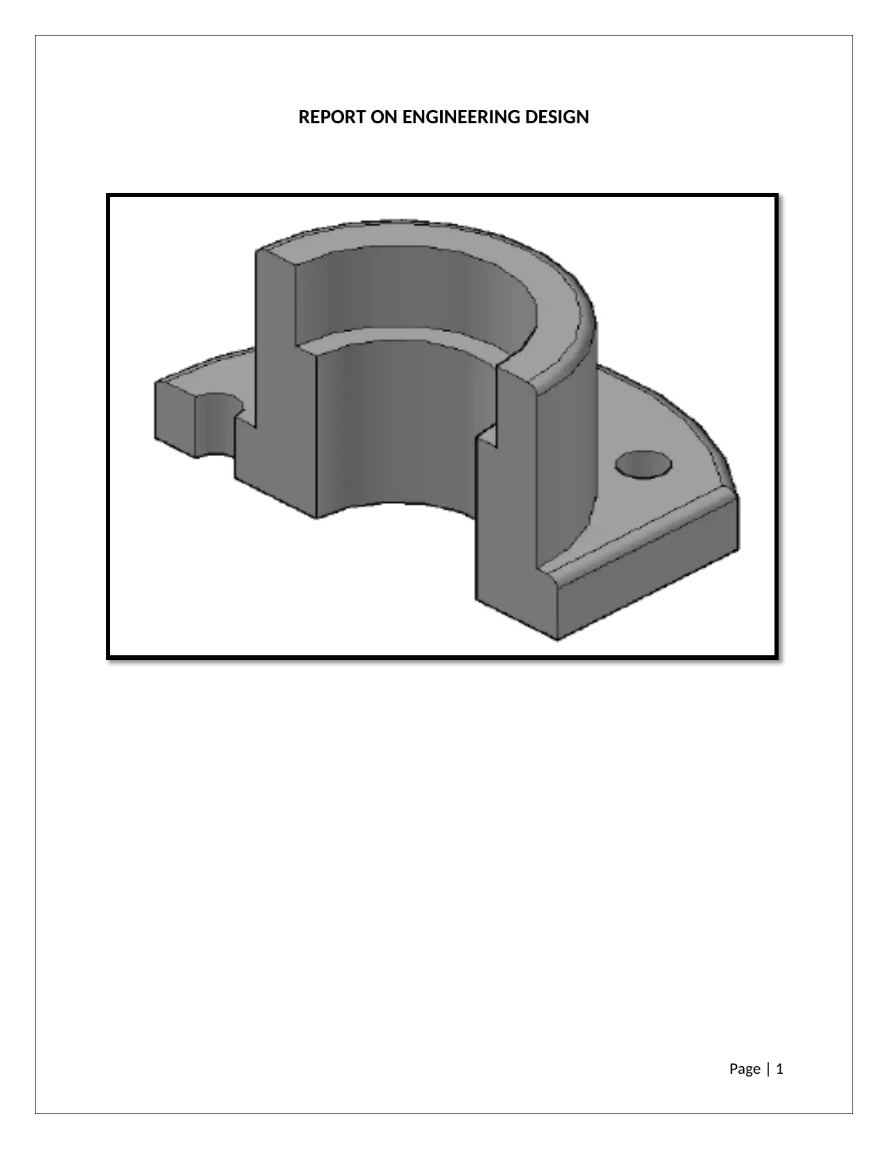
REPORT ON ENGINEERING DESIGN
REPORT ON ENGINEERING DESIGN
Paraphrase This Document
Need a fresh take? Get an instant paraphrase of this document with our AI Paraphraser
Page | 2
TASK 1
INTRODUCTION
CAD stands for computer aided design .CAD refers to the aid or help of computer, design any
component before it is actually manufactured.
BENEFITS
Improves in design quality
Improvement in design communication
Design documentation
Improves in designer productivity
Creating manufacturing routes via CAD-CAM
Easy modification in design/drawings
High design accuracy with least error margins
Easy accessible and usage (Lalit ,2008)
SELECTION OF CAD SOFTWARE
For 2D and 3D purpose the selected cad software that are widely used are shown below.
• AUTOCAD (2D Software)
Autocad is the 2D software generally used for preparing 2d sketches, process flow
diagrams and engineering drawings in 1st and 3rd angle projection.
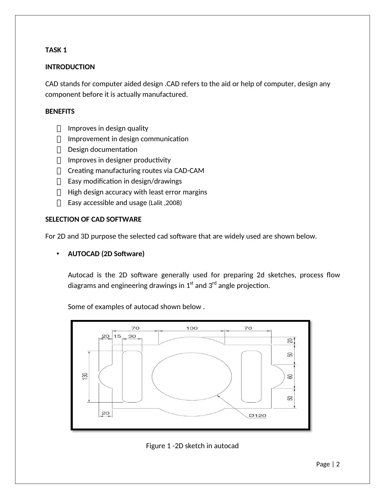
Some of examples of autocad shown below .
Figure 1 -2D sketch in autocad
Page | 3
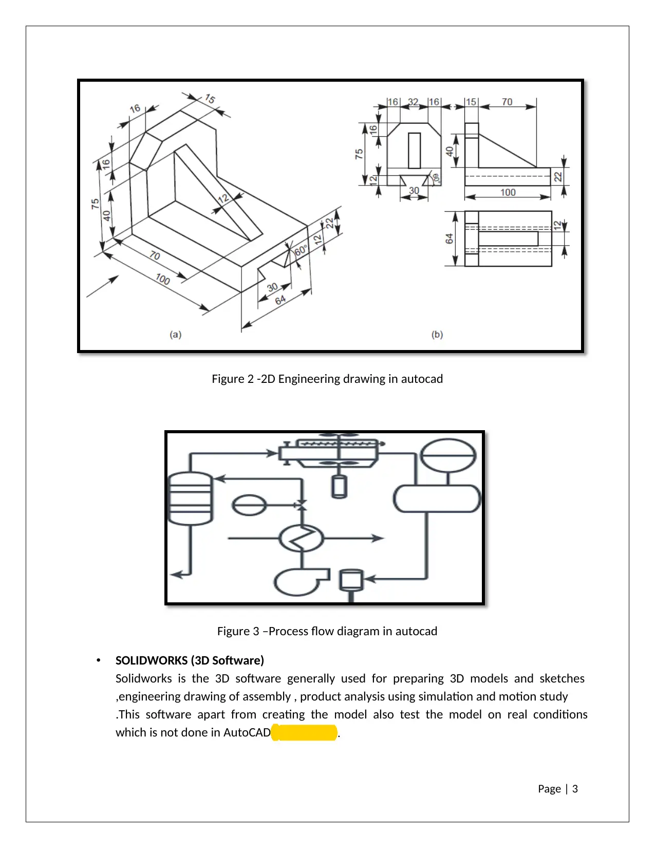
Figure 2 -2D Engineering drawing in autocad
Figure 3 –Process flow diagram in autocad
• SOLIDWORKS (3D Software)
Solidworks is the 3D software generally used for preparing 3D models and sketches
,engineering drawing of assembly , product analysis using simulation and motion study
.This software apart from creating the model also test the model on real conditions
which is not done in AutoCAD ( Yare ,2012) .
⊘ This is a preview!⊘
Do you want full access?
Subscribe today to unlock all pages.

Trusted by 1+ million students worldwide
Page | 4
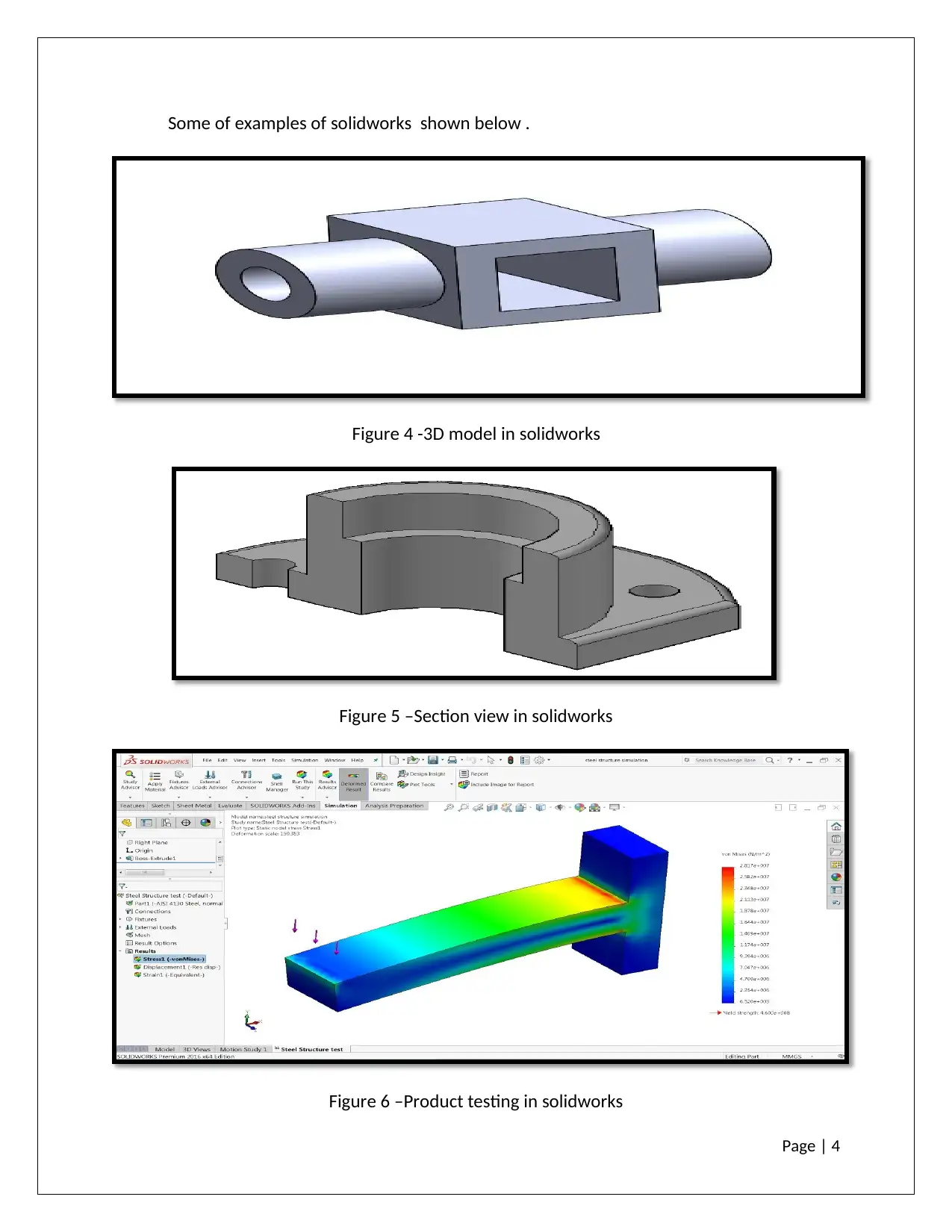
Some of examples of solidworks shown below .
Figure 4 -3D model in solidworks
Figure 5 –Section view in solidworks
Figure 6 –Product testing in solidworks
Some of examples of solidworks shown below .
Figure 4 -3D model in solidworks
Figure 5 –Section view in solidworks
Figure 6 –Product testing in solidworks
Paraphrase This Document
Need a fresh take? Get an instant paraphrase of this document with our AI Paraphraser
Page | 5
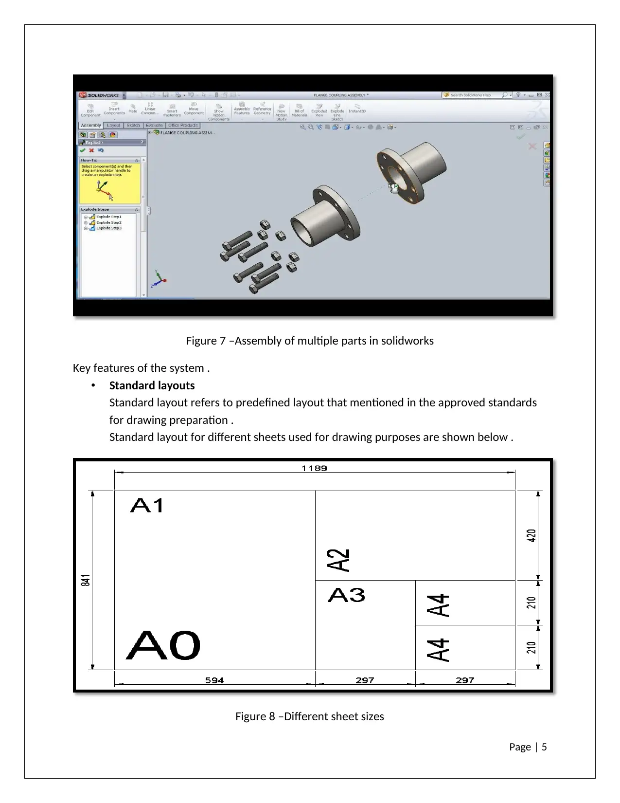
Figure 7 –Assembly of multiple parts in solidworks
Key features of the system .
• Standard layouts
Standard layout refers to predefined layout that mentioned in the approved standards
for drawing preparation .
Standard layout for different sheets used for drawing purposes are shown below .
Figure 8 –Different sheet sizes
Page | 6
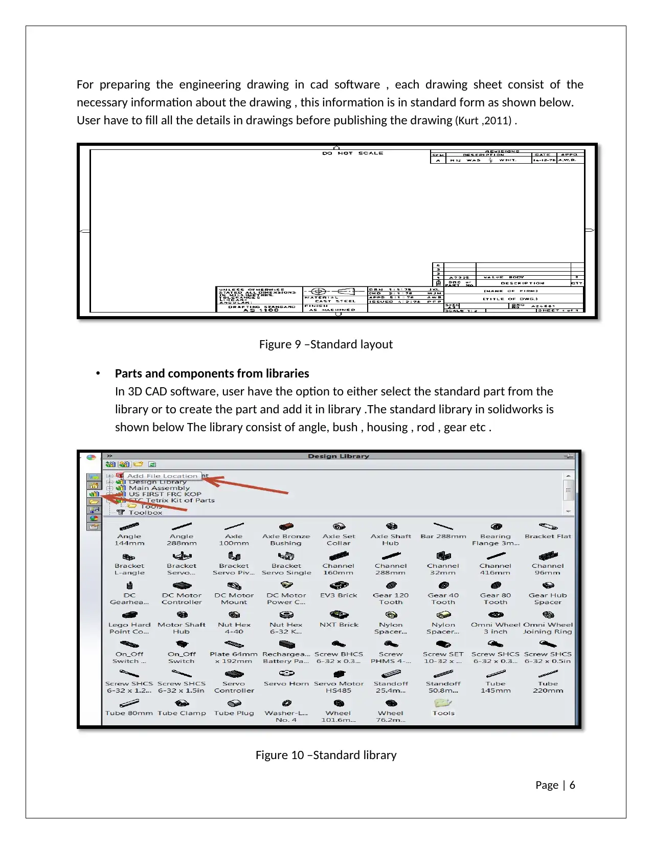
For preparing the engineering drawing in cad software , each drawing sheet consist of the
necessary information about the drawing , this information is in standard form as shown below.
User have to fill all the details in drawings before publishing the drawing (Kurt ,2011) .
Figure 9 –Standard layout
• Parts and components from libraries
In 3D CAD software, user have the option to either select the standard part from the
library or to create the part and add it in library .The standard library in solidworks is
shown below The library consist of angle, bush , housing , rod , gear etc .
Figure 10 –Standard library
⊘ This is a preview!⊘
Do you want full access?
Subscribe today to unlock all pages.

Trusted by 1+ million students worldwide
Page | 7
• Engineering calculations (such as Centre of Gravity, costing, etc.)
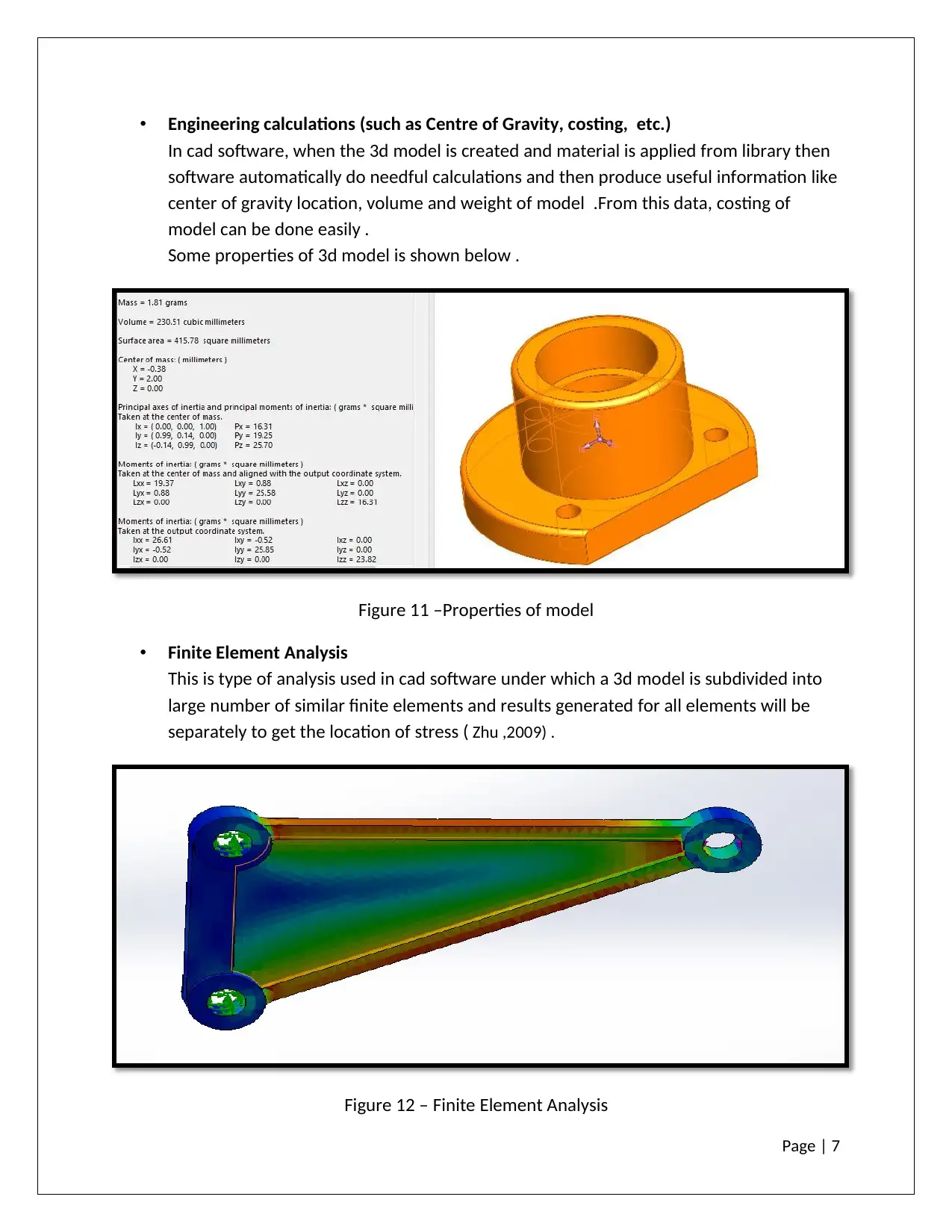
In cad software, when the 3d model is created and material is applied from library then
software automatically do needful calculations and then produce useful information like
center of gravity location, volume and weight of model .From this data, costing of
model can be done easily .
Some properties of 3d model is shown below .
Figure 11 –Properties of model
• Finite Element Analysis
This is type of analysis used in cad software under which a 3d model is subdivided into
large number of similar finite elements and results generated for all elements will be
separately to get the location of stress ( Zhu ,2009) .
Figure 12 – Finite Element Analysis
Paraphrase This Document
Need a fresh take? Get an instant paraphrase of this document with our AI Paraphraser
Page | 8
• Materials
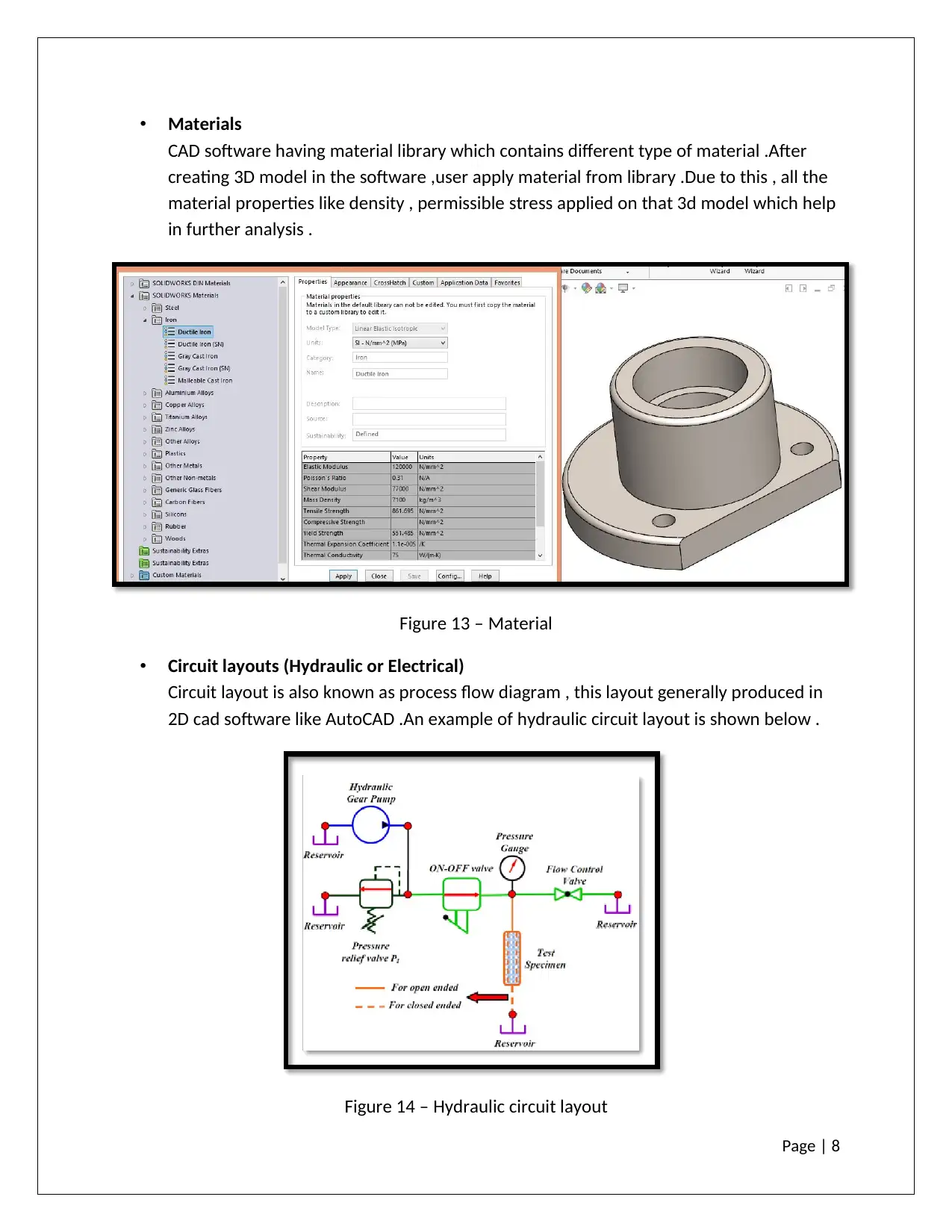
CAD software having material library which contains different type of material .After
creating 3D model in the software ,user apply material from library .Due to this , all the
material properties like density , permissible stress applied on that 3d model which help
in further analysis .
Figure 13 – Material
• Circuit layouts (Hydraulic or Electrical)
Circuit layout is also known as process flow diagram , this layout generally produced in
2D cad software like AutoCAD .An example of hydraulic circuit layout is shown below .
Figure 14 – Hydraulic circuit layout
Page | 9
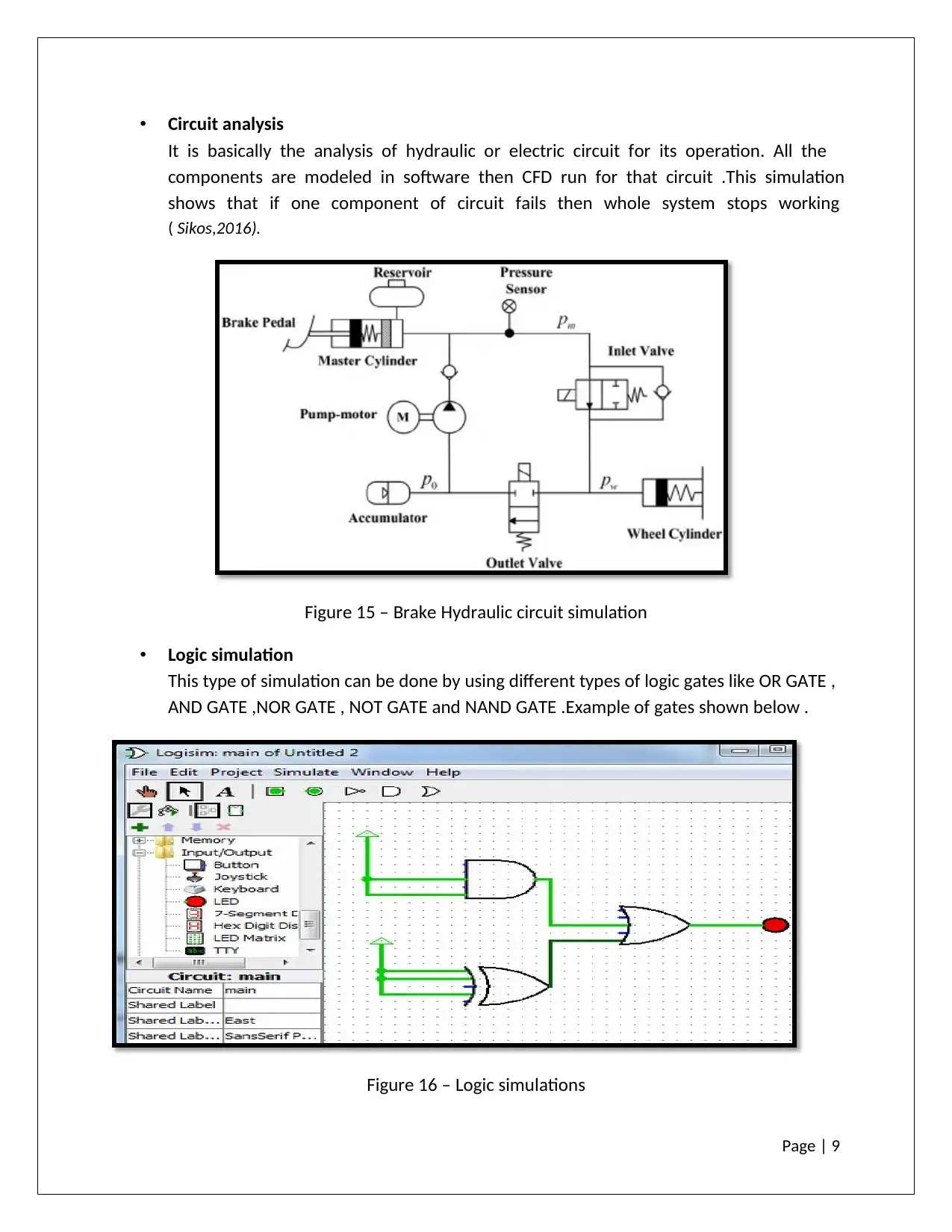
• Circuit analysis
It is basically the analysis of hydraulic or electric circuit for its operation. All the
components are modeled in software then CFD run for that circuit .This simulation
shows that if one component of circuit fails then whole system stops working
( Sikos,2016).
Figure 15 – Brake Hydraulic circuit simulation
• Logic simulation
This type of simulation can be done by using different types of logic gates like OR GATE ,
AND GATE ,NOR GATE , NOT GATE and NAND GATE .Example of gates shown below .
Figure 16 – Logic simulations
⊘ This is a preview!⊘
Do you want full access?
Subscribe today to unlock all pages.

Trusted by 1+ million students worldwide
Page | 10
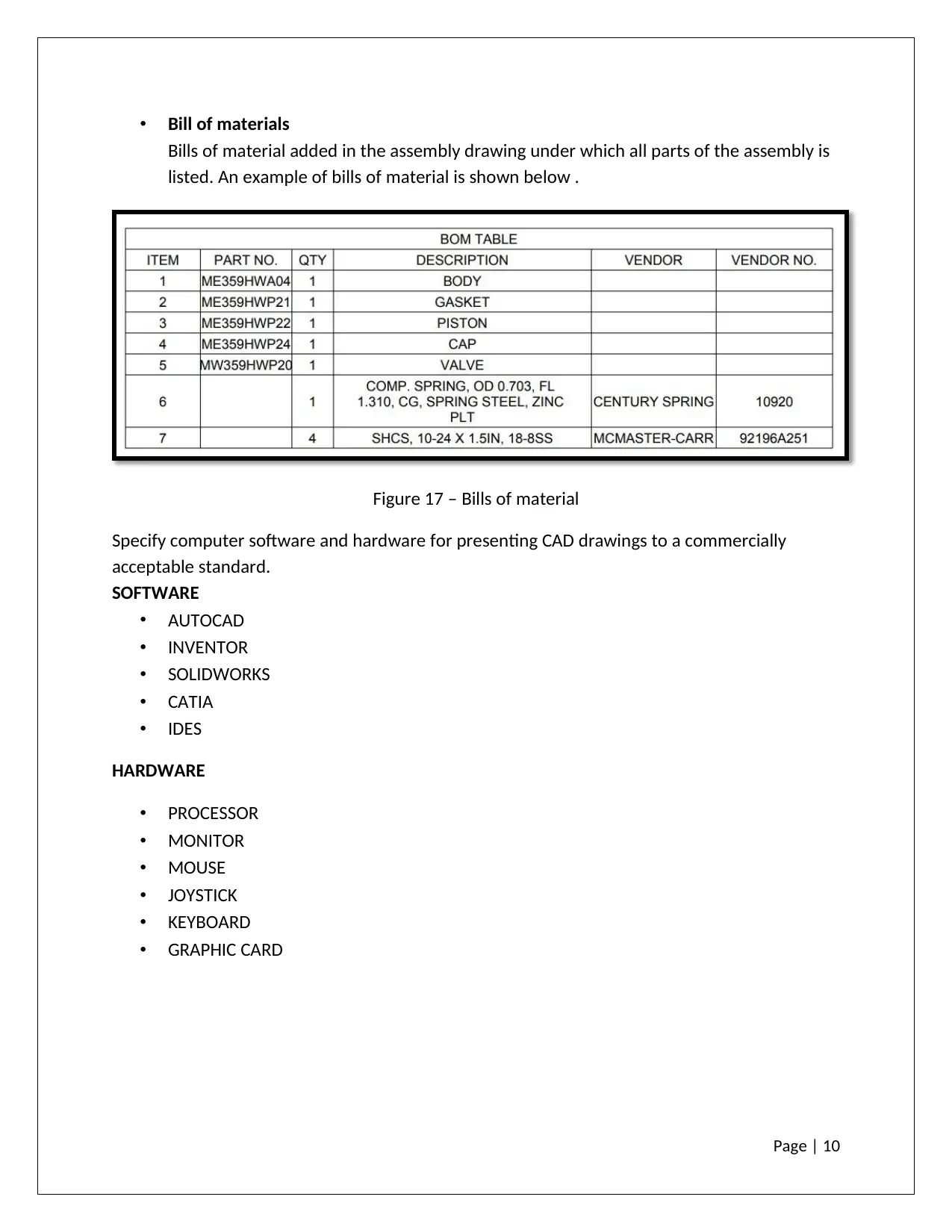
• Bill of materials
Bills of material added in the assembly drawing under which all parts of the assembly is
listed. An example of bills of material is shown below .
Figure 17 – Bills of material
Specify computer software and hardware for presenting CAD drawings to a commercially
acceptable standard.
SOFTWARE
• AUTOCAD
• INVENTOR
• SOLIDWORKS
• CATIA
• IDES
HARDWARE
• PROCESSOR
• MONITOR
• MOUSE
• JOYSTICK
• KEYBOARD
• GRAPHIC CARD
Paraphrase This Document
Need a fresh take? Get an instant paraphrase of this document with our AI Paraphraser
Page | 11
TASK 2
Calculations for cost per seat
• Cost of one license of CAD software is = 4000$
• Cost of one workstation = 2500 $
• Cost of maintenance and upgradation of cad software per year = 1300 $
• Cost of maintenance of workstation per month = 100 $
In the initial year cost per seat will be = 4000 +2500+1300+100*12 = 9000$
Therefore the cost per seat will be 9000 $
Specification of selected units above.
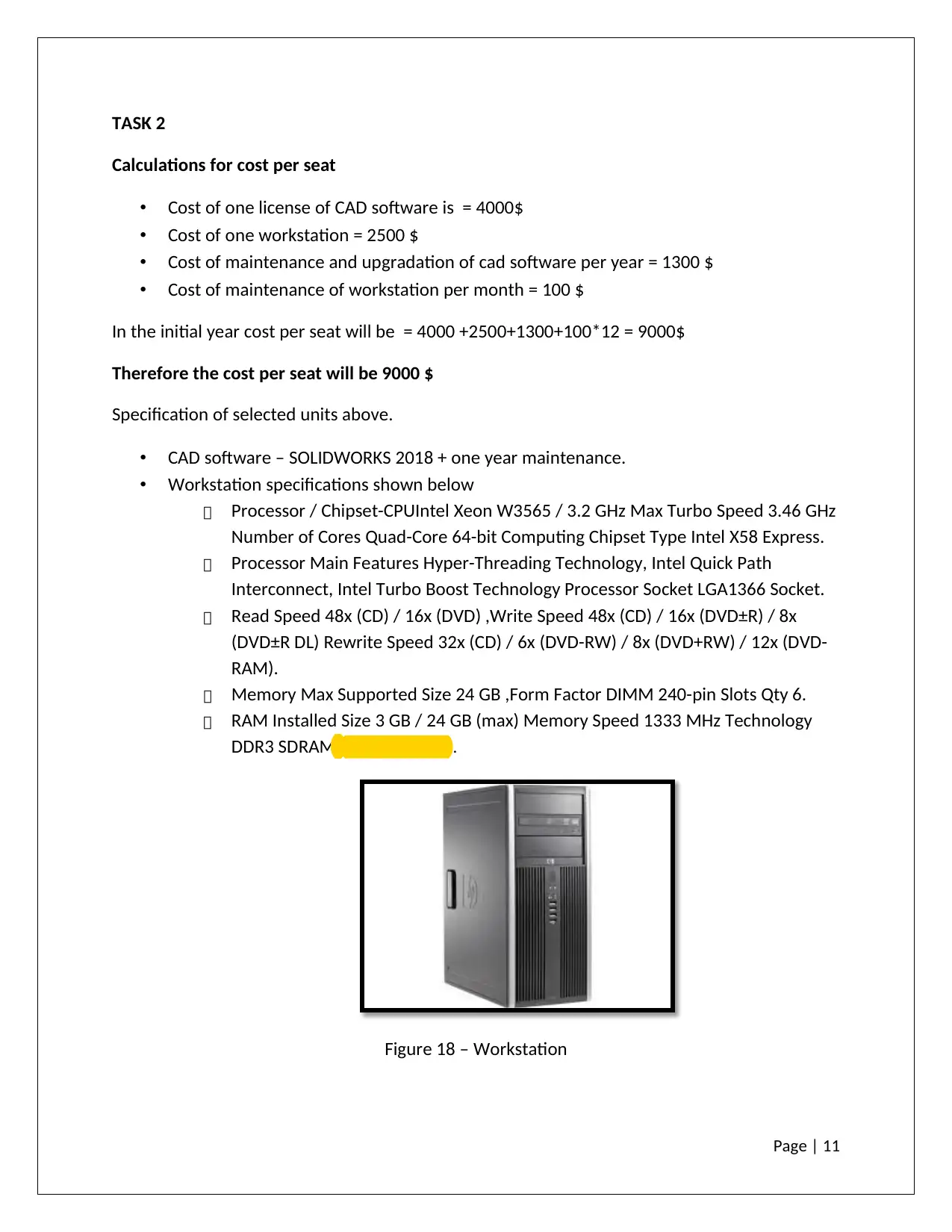
• CAD software – SOLIDWORKS 2018 + one year maintenance.
• Workstation specifications shown below
Processor / Chipset-CPUIntel Xeon W3565 / 3.2 GHz Max Turbo Speed 3.46 GHz
Number of Cores Quad-Core 64-bit Computing Chipset Type Intel X58 Express.
Processor Main Features Hyper-Threading Technology, Intel Quick Path
Interconnect, Intel Turbo Boost Technology Processor Socket LGA1366 Socket.
Read Speed 48x (CD) / 16x (DVD) ,Write Speed 48x (CD) / 16x (DVD±R) / 8x
(DVD±R DL) Rewrite Speed 32x (CD) / 6x (DVD-RW) / 8x (DVD+RW) / 12x (DVD-
RAM).
Memory Max Supported Size 24 GB ,Form Factor DIMM 240-pin Slots Qty 6.
RAM Installed Size 3 GB / 24 GB (max) Memory Speed 1333 MHz Technology
DDR3 SDRAM( Bernard ,2010) .
Figure 18 – Workstation
Page | 12
How compatible would this be with the software of other companies?Analyse the functions of
CAD and state how it could benefit other departments within the company. (e.g. Marketing,
manufacturing, management planning, safety, etc.)
• A manufacturing company having multiple departments like design, production, quality,
management, planning and purchase departments. So cad will be helpful in
communication within different departments of company.
• Company has to provide the workstations along with cad software in every department
for effective communication.
• When the design department prepares drawings in their workstations for particular
design then that drawings are printed and issued in all other departments.
• After getting the drawing from design departments all other departments start their
work further to complete the part. For example the production/manufacturing
department start preparing the part ,purchase department start generating the indent
of bought out items used in assembly of part , store department start looking for the
parts already available in the inventory .
• As store department after getting the drawings from design department check if
necessary material for making the assembly is already available then it update to
purchase department about that.
• If company not having necessary equipments for product manufacturing or if standard
part available in the market then it informs the update to design department through
drawings then design department update the drawings and reissue again in all
department .Due to this ,changes in the design updates in all department and margin of
error reduces .
⊘ This is a preview!⊘
Do you want full access?
Subscribe today to unlock all pages.

Trusted by 1+ million students worldwide
1 out of 13
Related Documents
Your All-in-One AI-Powered Toolkit for Academic Success.
+13062052269
info@desklib.com
Available 24*7 on WhatsApp / Email
![[object Object]](/_next/static/media/star-bottom.7253800d.svg)
Unlock your academic potential
Copyright © 2020–2025 A2Z Services. All Rights Reserved. Developed and managed by ZUCOL.


