Porous Nitinol Knee Implants and 3D Printing
VerifiedAdded on 2020/10/03
|12
|5676
|135
AI Summary
This assignment provides a detailed overview of porous nitinol, a high-strength, low-stiffness metal alloy that resembles bone. It discusses the use of porous nitinol in knee implants, its osseo integration properties, and the challenges of nickel leaching. The assignment also touches on the benefits of 3D printing in customizing these implants, including the ability to engineer porosity and promote osseo integration. A case study of a British opera singer who underwent total knee replacement surgery using 3D printed knee implants is presented, highlighting the potential of this technology.
Contribute Materials
Your contribution can guide someone’s learning journey. Share your
documents today.
ENGINEERING MATERIALS IN MEDICINE
ME6505
GROUP PROJECT
Prof. Seeram Ramakrishna
Assoc Prof. Thian Eng San
TEAM 8: KNEE IMPLANT
Submitted by,
Dai Zhenwei
Kalaiselvan Vimareesan
Mullapudi Sneha Sree
Pan Bo
Rajagopalan Eswaran
Ramasamy Vignesh
Raveendra Ramgopal
Shi Zhirui
Suhail Mohammed Hussain
Wang Haiming
ME6505
GROUP PROJECT
Prof. Seeram Ramakrishna
Assoc Prof. Thian Eng San
TEAM 8: KNEE IMPLANT
Submitted by,
Dai Zhenwei
Kalaiselvan Vimareesan
Mullapudi Sneha Sree
Pan Bo
Rajagopalan Eswaran
Ramasamy Vignesh
Raveendra Ramgopal
Shi Zhirui
Suhail Mohammed Hussain
Wang Haiming
Secure Best Marks with AI Grader
Need help grading? Try our AI Grader for instant feedback on your assignments.

1
CONTENTS
1. Introduction ........................................................................................................................................................2
1.1. Key functions of the Knee ...........................................................................................................................2
1.2. Need for Knee replacement ...........................................................................................................................2
2. Knee Replacement Prosthesis ....................................................................................................................................... 3
2.1. Knee Implant Designs ............................................................................................................................................... 3
2.2. Implant Fixation .............................................................................................................................................3
3. Bio-materials ................................................................................................................................................................... 4
3.1. Requirements for Bio Material ............................................................................................................................... 4
3.2. Selection of Material .....................................................................................................................................5
4. 3D printing of Knee implant ..............................................................................................................................7
4.1. Printing of Tibial Insert / Spacer and Patellar Component ..........................................................................7
4.2. Printing of Femoral and Tibial Component ..................................................................................................8
5. Issues ....................................................................................................................................................................9
5.1. Biocompatibility of Nitinol ..........................................................................................................................9
5.2. Issues in 3D printing NiTi using SLM ..........................................................................................................9
6. Medical Applications of Nitinol .......................................................................................................................10
7. Market Survey for 3D printed knee implants ...................................................................................................10
8. Conclusion ........................................................................................................................................................11
9. References .........................................................................................................................................................11
2
1. Introduction
The knee joint is one of the most critical, largest and strongest joint in the human body. It helps in joining the
lower leg with the thigh and enables the former to move relative to the latter while supporting the body’s weight
at the same time. There are three bones which constitute a knee joint which are the femur, the patella, and the
tibia. The patella is otherwise called as knee cap. The femur and the tibia are also referred to as thigh bone and
the main bone of the lower leg respectively. The meniscus, which is a layer of tough, rubbery fibrocartilage
between tibia and femur, functions as a shock absorbing element for preventing collision between the leg bones
during jumping, running and other activities. The joint capsule contains the synovial membrane which produces
the synovial fluid to lubricate the knee. [1]
1.1.Key functions of the Knee
The knee is a joint comprising of complex movements in various directions with the help of multiple bones. The
movements include bending (flexion), straightening (extension), gliding of femur on top of the tibia in forward
and backward directions (translation) and also inward rotation of femur (internal rotation) or in outward
direction (external rotation) with respect to the tibia. Range of motion (ROM) measurements helps to evaluate
the functioning of a joint and is measured with functional and passive measurements which differ depending
upon gender and age. The ROM values for a normal knee are, flexion from 0 to 160 o and extension up to 0o and
in some cases up to -10 o which condition is referred to as hyperextension. The maximum patellar compression
force generally is 7 fold of one’s body weight and the maximum compressive load on the tibial and femoral
component would be 5.6 times body weight (values taken during squatting activity). [6] [7]
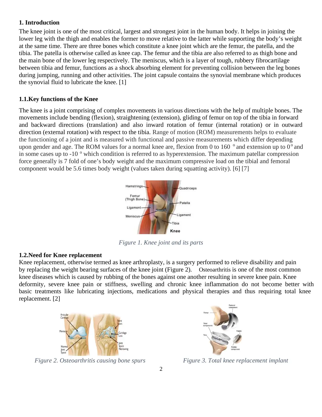
Figure 1. Knee joint and its parts
1.2.Need for Knee replacement
Knee replacement, otherwise termed as knee arthroplasty, is a surgery performed to relieve disability and pain
by replacing the weight bearing surfaces of the knee joint (Figure 2). Osteoarthritis is one of the most common
knee diseases which is caused by rubbing of the bones against one another resulting in severe knee pain. Knee
deformity, severe knee pain or stiffness, swelling and chronic knee inflammation do not become better with
basic treatments like lubricating injections, medications and physical therapies and thus requiring total knee
replacement. [2]
Figure 2. Osteoarthritis causing bone spurs Figure 3. Total knee replacement implant
3
2. Knee Replacement Prosthesis
The total knee replacement prosthesis or knee implant consists of three main components. They are the femoral
component, the tibial component and the spacing made of plastic (usually polyethylene) between the two
components, as shown in Figure 3. The femoral component is attached to the lower end of the femur and is
grooved to allow for smooth movement of knee cap against the bone. The tibial component, attached to the tibia
on its upper end, is basically a flat metal platform with a plastioc spacer as a cushion on the top and a stem at
the bottom that fits into the centre of the tibial bone. [3]
2.1.Knee Implant Designs
There are several knee implant designs in the market. But the most common knee implant designs are [4][5]:
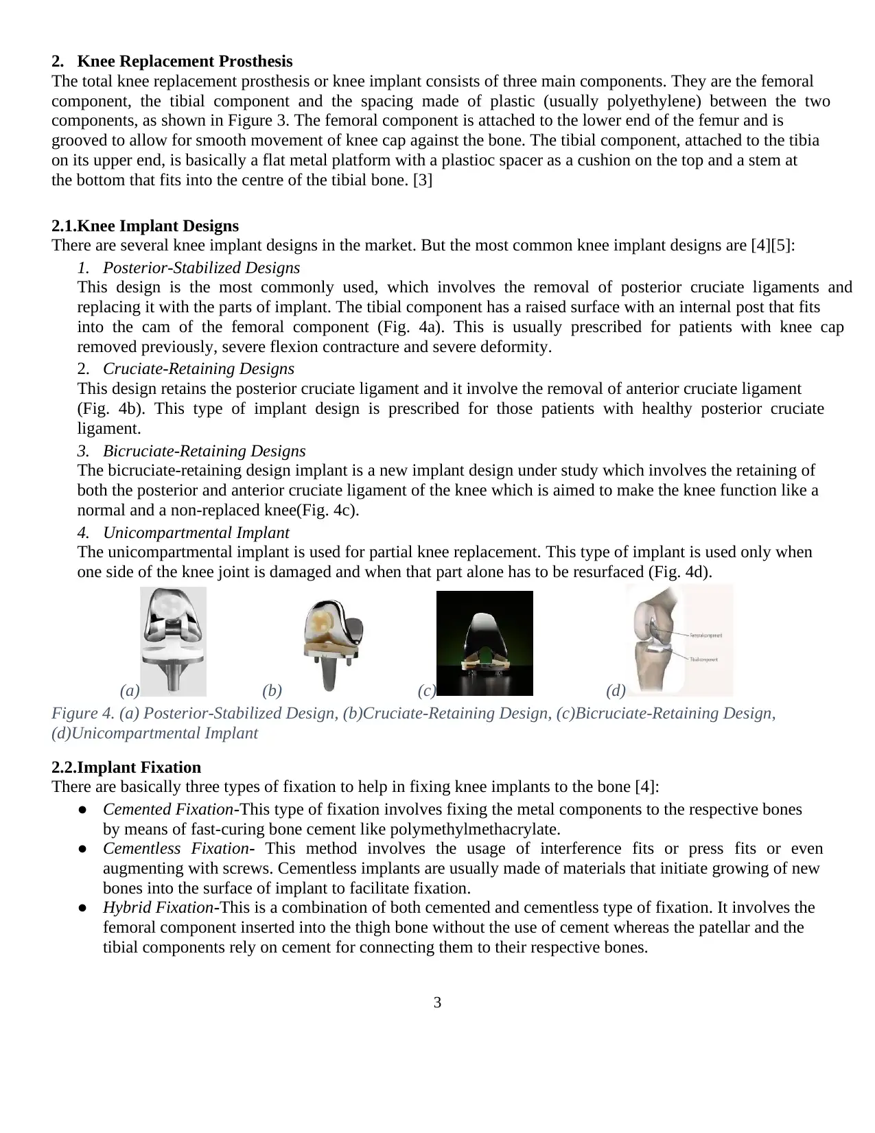
1. Posterior-Stabilized Designs
This design is the most commonly used, which involves the removal of posterior cruciate ligaments and
replacing it with the parts of implant. The tibial component has a raised surface with an internal post that fits
into the cam of the femoral component (Fig. 4a). This is usually prescribed for patients with knee cap
removed previously, severe flexion contracture and severe deformity.
2. Cruciate-Retaining Designs
This design retains the posterior cruciate ligament and it involve the removal of anterior cruciate ligament
(Fig. 4b). This type of implant design is prescribed for those patients with healthy posterior cruciate
ligament.
3. Bicruciate-Retaining Designs
The bicruciate-retaining design implant is a new implant design under study which involves the retaining of
both the posterior and anterior cruciate ligament of the knee which is aimed to make the knee function like a
normal and a non-replaced knee(Fig. 4c).
4. Unicompartmental Implant
The unicompartmental implant is used for partial knee replacement. This type of implant is used only when
one side of the knee joint is damaged and when that part alone has to be resurfaced (Fig. 4d).
(a) (b) (c) (d)
Figure 4. (a) Posterior-Stabilized Design, (b)Cruciate-Retaining Design, (c)Bicruciate-Retaining Design,
(d)Unicompartmental Implant
2.2.Implant Fixation
There are basically three types of fixation to help in fixing knee implants to the bone [4]:
● Cemented Fixation-This type of fixation involves fixing the metal components to the respective bones
by means of fast-curing bone cement like polymethylmethacrylate.
● Cementless Fixation- This method involves the usage of interference fits or press fits or even
augmenting with screws. Cementless implants are usually made of materials that initiate growing of new
bones into the surface of implant to facilitate fixation.
● Hybrid Fixation-This is a combination of both cemented and cementless type of fixation. It involves the
femoral component inserted into the thigh bone without the use of cement whereas the patellar and the
tibial components rely on cement for connecting them to their respective bones.
Secure Best Marks with AI Grader
Need help grading? Try our AI Grader for instant feedback on your assignments.

4
3. Bio-materials:
The materials or substances that are particularly engineered to have the biological interaction for
medical purposes. It can be used for diagnostic purpose or to perform medical repair or replacing tissue
functions.
3.1. Requirements for Bio Material
3.1.1. Mechanical Properties
The bio materials has to be chosen carefully based on various properties. Each material interact with the
body in different ways. The mechanical properties are the key factors for selection. Some of the important
properties are as follows [8]
Fatigue Life
The fatigue life defines the ability of the material to withstand repeated cyclic loads. As the knee implant is
imposed to a huge cyclic loading, this is one of the major considerations in material selection. The
microstructure of the material is responsible to have a better life.
Adequate Strength
The strength of the material used for the implant is also one of the major consideration as it affects the human in
two different ways- Impact on internal organs, Impact on ergonomics of the human. It starts to fail, as the
human body develops the fibrous soft tissue in the gap between the implant and bone. Which is the cause for
unbearable pain to the patient.
Modulus equivalent to that of bone
For better life, the modulus difference can cause the stress shielding effect which is extremely dangerous as it
can deteriorate the implant or even the bone of the patient. As a result, loosening of the implant take place
causing the failure. For this reason, choosing a material with the modulus that is very close to the modulus of
the bone is considered as an important property. The modulus ranges from 4GPa to 30GPa depending on
measurement direction and type and strength of the bone.
3.1.2. Non-Mechanical Requirements
High corrosion resistance
Corrosion resistance is an important property, as the body fluid is unavoidable in the biomedical conditions.
Corrosion will reduce the implant life and it may lead to multiple number of surgeries. If the metal ions
dissolve, they get accumulated in the tissues closer to the implants and later it may flow to the other parts of the
human body [8]
High wear resistance
When the resistance to wear is low or when the friction coefficient is low, it result in loosening of the implant.
As a result, debris is formed and it’s biologically active causing inflammatory issues which result in bone
destruction. It can also lead to corrosion fatigue due to friction. [8]
Biocompatibility and Osseo integration
Biocompatibility is the most important requirement. It is the characteristic of the material to exist within the
human body without any harm to the body. It covers a wide area not pointing to toxicity alone. They are
classified as inert, active and degradable materials.
The requirement is that, the material selected should improve the quality and rate of bone apposition and should
not alter the homeostasis of the surrounding soft tissue and bone. [8]
5
3.2. Selection of Material:
The biomedical implants are made from different type of the materials including the ceramics, polymers, metals
and also the composites. The total knee replacement consists of following major components.
1. Femoral component
2. Tibial component
3. Tibial insert or spacer
4. Patellar Component
The Tibial and Femoral components are usually of made of metals due to the requirement of strength and the
Spacer and Patellar component is made of polyethylene. From the survey on various plastic materials for Tibial
insert / spacer and Patellar Component it is inferred that Ultra high molecular weight polyethylene (UHMWPE)
is most preferred and economical solution as far as the material wear rates are concerned. The material is
compared with CFR PEEK which possesses good bio compatibility. Due to the fact that 3D printing of
UHMWPE is not acceptable, as it is very difficult to favour printing of UHMWPE and the mechanical
properties of 3D printed UHMWPE does not fulfil the requirements, UHMWPE (40%) blended with HDPE
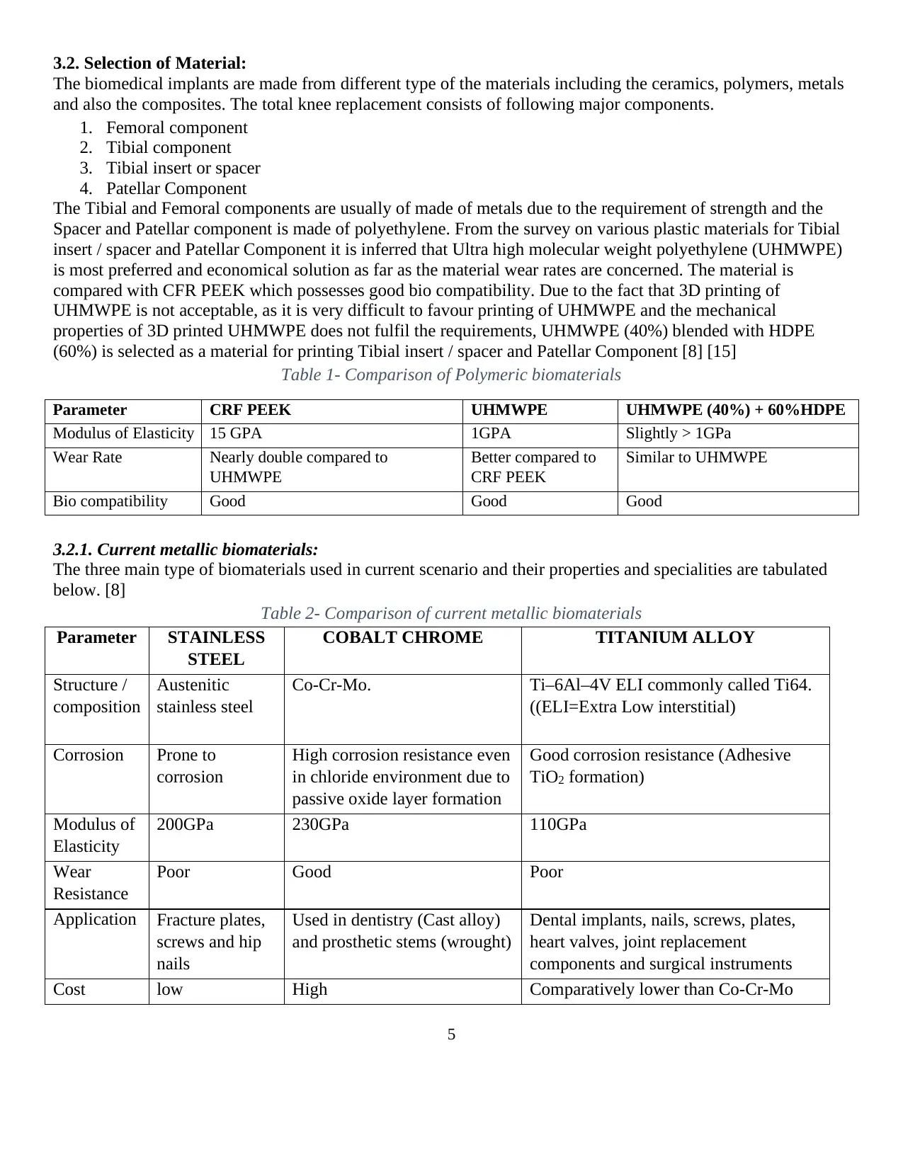
(60%) is selected as a material for printing Tibial insert / spacer and Patellar Component [8] [15]
Table 1- Comparison of Polymeric biomaterials
Parameter CRF PEEK UHMWPE UHMWPE (40%) + 60%HDPE
Modulus of Elasticity 15 GPA 1GPA Slightly > 1GPa
Wear Rate Nearly double compared to
UHMWPE
Better compared to
CRF PEEK
Similar to UHMWPE
Bio compatibility Good Good Good
3.2.1. Current metallic biomaterials:
The three main type of biomaterials used in current scenario and their properties and specialities are tabulated
below. [8]
Table 2- Comparison of current metallic biomaterials
Parameter STAINLESS
STEEL
COBALT CHROME TITANIUM ALLOY
Structure /
composition
Austenitic
stainless steel
Co-Cr-Mo. Ti–6Al–4V ELI commonly called Ti64.
((ELI=Extra Low interstitial)
Corrosion Prone to
corrosion
High corrosion resistance even
in chloride environment due to
passive oxide layer formation
Good corrosion resistance (Adhesive
TiO2 formation)
Modulus of
Elasticity
200GPa 230GPa 110GPa
Wear
Resistance
Poor Good Poor
Application Fracture plates,
screws and hip
nails
Used in dentistry (Cast alloy)
and prosthetic stems (wrought)
Dental implants, nails, screws, plates,
heart valves, joint replacement
components and surgical instruments
Cost low High Comparatively lower than Co-Cr-Mo
6
3.2.2. Porous Nickel-Titanium (Porous Nitinol)
The material selected for Femoral and Tibial component is Porous Nickel-Titanium (Porous Nitinol) which is a
Shape memory alloy.
Shape memory is the characteristic of the material to remember its undeformed shape, which it regains upon
heating above its “transition temperature” (Phase transition) once deformed. Phase transition determines the
properties of the shape memory alloys. Martensite is a ductile and soft form and hence it can be deformed
easily. Stress induced martensite is super elastic and austenitic is the harder form. The young’s modulus of these
shape memory alloy phase transition forms is very less. This low modulus makes it a best material for implants
regarding the bones as they have the modulus closer to that of the bones. Also the fatigue resistance properties
of these materials favour their application. They have a very high resistance to wear and also are nonmagnetic.
This special property enables the usage of MRI. [8] [9]
Porosity of 16% in the component (Femoral & Tibial) is achieved by engineering porosity in the CAD model
which serves as the basis for 3D printing. [8]
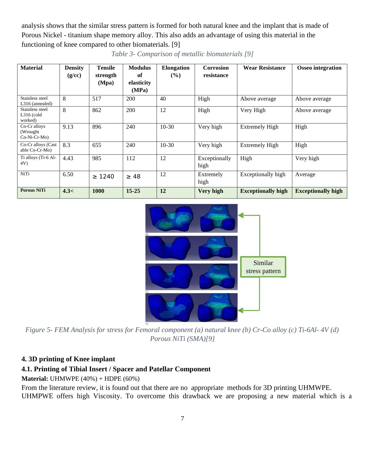
Some of the special properties of NiTi with porosity of 16% are as follows.
Strength 1000MPa
Compressive ductility >7%
High energy absorption >30 MJ/m3
Young’s Modulus 15-25 GPa
Recoverable Strain >6%
The porosity of the material is necessary for high toughness and high strength with comparatively lesser
stiffness. Strength is essential, as it helps in avoiding fracture or deformation, Toughness is important
characteristic that prevents brittle fracture and low modulus of elasticity (Stiffness) helps in minimising stress
shielding effects.
Biocompatibility and surface treatment
Compared to conventional materials in porous form including the stainless steel and titanium, porous NiTiis
biocompatible. The tissue responses are not adverse and there is no fibrous tissues formed at interfaces. It also
shows better osseo integration and osseo conductivity. There are issues in resistivity to corrosion as it may
release abnormal amount of Ni, it’s of a comparative risk. Proper surface treatment and coatings can bring the
Ni release into control. [8]
Superelastic behaviour
Super-elastic materials are those that come back to the original shape after unloading even after a considerable
amount of deformation. Phase transition is responsible for this ability. So it’s useful in knee replacement where
the frequency of load is very high as the human movement causes cyclic and variable loads. [8]
Damping capacity
The ability to transform one king of energy to other is called damping effect. This material has a very high
damping effect and as a result it provides a irreversible energy transformation. This makes it better when the
considerations are shocks and vibration as it absorbs them permanently. [8]
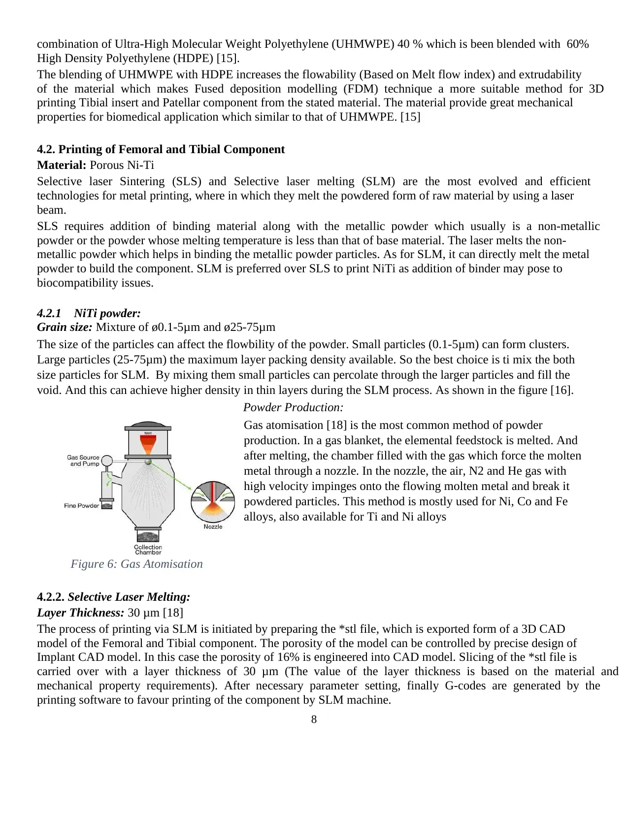
Based on the finite element analysis, the stress pattern is found for each biomaterial and the inferences from the
Paraphrase This Document
Need a fresh take? Get an instant paraphrase of this document with our AI Paraphraser
7
analysis shows that the similar stress pattern is formed for both natural knee and the implant that is made of
Porous Nickel - titanium shape memory alloy. This also adds an advantage of using this material in the
functioning of knee compared to other biomaterials. [9]
Table 3- Comparison of metallic biomaterials [9]
Material Density
(g/cc)
Tensile
strength
(Mpa)
Modulus
of
elasticity
(MPa)
Elongation
(%)
Corrosion
resistance
Wear Resistance Osseo integration
Stainless steel
L316 (annealed) 8 517 200 40 High Above average Above average
Stainless steel
L316 (cold
worked)
8 862 200 12 High Very High Above average
Co-Cr alloys
(Wrought
Co-Ni-Cr-Mo)
9.13 896 240 10-30 Very high Extremely High High
Co-Cr alloys (Cast
able Co-Cr-Mo) 8.3 655 240 10-30 Very high Extremely High High
Ti alloys (Ti-6 Al-
4V) 4.43 985 112 12 Exceptionally
high
High Very high
NiTi 6.50 ≥ 1240 ≥ 48 12 Extremely
high
Exceptionally high Average
Porous NiTi 4.3< 1000 15-25 12 Very high Exceptionally high Exceptionally high
Figure 5- FEM Analysis for stress for Femoral component (a) natural knee (b) Cr-Co alloy (c) Ti-6Al- 4V (d)
Porous NiTi (SMA)[9]
4. 3D printing of Knee implant
4.1. Printing of Tibial Insert / Spacer and Patellar Component
Material: UHMWPE (40%) + HDPE (60%)
From the literature review, it is found out that there are no appropriate methods for 3D printing UHMWPE.
UHMPWE offers high Viscosity. To overcome this drawback we are proposing a new material which is a
Similar
stress pattern
8
combination of Ultra-High Molecular Weight Polyethylene (UHMWPE) 40 % which is been blended with 60%
High Density Polyethylene (HDPE) [15].
The blending of UHMWPE with HDPE increases the flowability (Based on Melt flow index) and extrudability
of the material which makes Fused deposition modelling (FDM) technique a more suitable method for 3D
printing Tibial insert and Patellar component from the stated material. The material provide great mechanical
properties for biomedical application which similar to that of UHMWPE. [15]
4.2. Printing of Femoral and Tibial Component
Material: Porous Ni-Ti
Selective laser Sintering (SLS) and Selective laser melting (SLM) are the most evolved and efficient
technologies for metal printing, where in which they melt the powdered form of raw material by using a laser
beam.
SLS requires addition of binding material along with the metallic powder which usually is a non-metallic
powder or the powder whose melting temperature is less than that of base material. The laser melts the non-
metallic powder which helps in binding the metallic powder particles. As for SLM, it can directly melt the metal
powder to build the component. SLM is preferred over SLS to print NiTi as addition of binder may pose to
biocompatibility issues.
4.2.1 NiTi powder:
Grain size: Mixture of ø0.1-5μm and ø25-75μm
The size of the particles can affect the flowbility of the powder. Small particles (0.1-5μm) can form clusters.
Large particles (25-75μm) the maximum layer packing density available. So the best choice is ti mix the both
size particles for SLM. By mixing them small particles can percolate through the larger particles and fill the
void. And this can achieve higher density in thin layers during the SLM process. As shown in the figure [16].
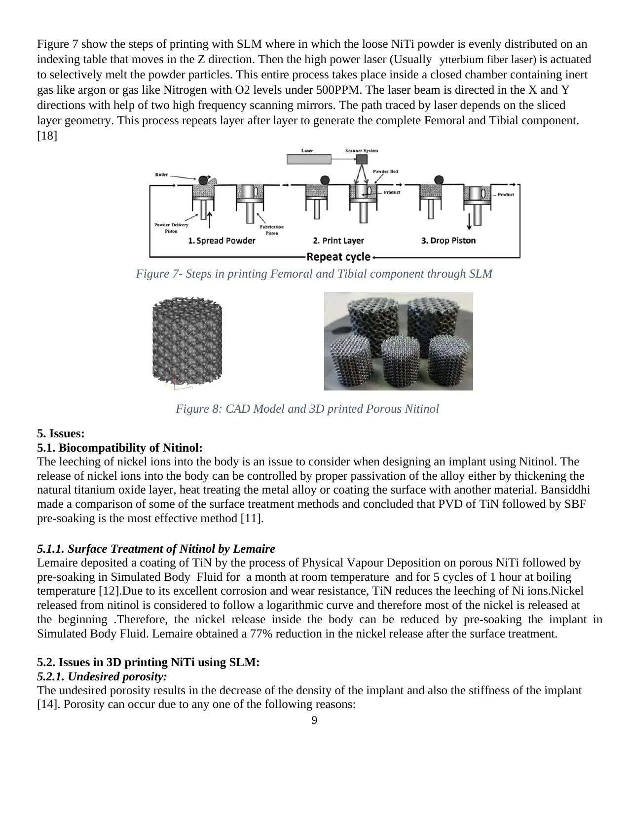
Powder Production:
Gas atomisation [18] is the most common method of powder
production. In a gas blanket, the elemental feedstock is melted. And
after melting, the chamber filled with the gas which force the molten
metal through a nozzle. In the nozzle, the air, N2 and He gas with
high velocity impinges onto the flowing molten metal and break it
powdered particles. This method is mostly used for Ni, Co and Fe
alloys, also available for Ti and Ni alloys
Figure 6: Gas Atomisation
4.2.2. Selective Laser Melting:
Layer Thickness: 30 μm [18]
The process of printing via SLM is initiated by preparing the *stl file, which is exported form of a 3D CAD
model of the Femoral and Tibial component. The porosity of the model can be controlled by precise design of
Implant CAD model. In this case the porosity of 16% is engineered into CAD model. Slicing of the *stl file is
carried over with a layer thickness of 30 μm (The value of the layer thickness is based on the material and
mechanical property requirements). After necessary parameter setting, finally G-codes are generated by the
printing software to favour printing of the component by SLM machine.
9
Figure 7 show the steps of printing with SLM where in which the loose NiTi powder is evenly distributed on an
indexing table that moves in the Z direction. Then the high power laser (Usually ytterbium fiber laser) is actuated
to selectively melt the powder particles. This entire process takes place inside a closed chamber containing inert
gas like argon or gas like Nitrogen with O2 levels under 500PPM. The laser beam is directed in the X and Y
directions with help of two high frequency scanning mirrors. The path traced by laser depends on the sliced
layer geometry. This process repeats layer after layer to generate the complete Femoral and Tibial component.
[18]
Figure 7- Steps in printing Femoral and Tibial component through SLM
Figure 8: CAD Model and 3D printed Porous Nitinol
5. Issues:
5.1. Biocompatibility of Nitinol:
The leeching of nickel ions into the body is an issue to consider when designing an implant using Nitinol. The
release of nickel ions into the body can be controlled by proper passivation of the alloy either by thickening the
natural titanium oxide layer, heat treating the metal alloy or coating the surface with another material. Bansiddhi
made a comparison of some of the surface treatment methods and concluded that PVD of TiN followed by SBF
pre-soaking is the most effective method [11].
5.1.1. Surface Treatment of Nitinol by Lemaire
Lemaire deposited a coating of TiN by the process of Physical Vapour Deposition on porous NiTi followed by
pre-soaking in Simulated Body Fluid for a month at room temperature and for 5 cycles of 1 hour at boiling
temperature [12].Due to its excellent corrosion and wear resistance, TiN reduces the leeching of Ni ions.Nickel
released from nitinol is considered to follow a logarithmic curve and therefore most of the nickel is released at
the beginning .Therefore, the nickel release inside the body can be reduced by pre-soaking the implant in
Simulated Body Fluid. Lemaire obtained a 77% reduction in the nickel release after the surface treatment.
5.2. Issues in 3D printing NiTi using SLM:
5.2.1. Undesired porosity:
The undesired porosity results in the decrease of the density of the implant and also the stiffness of the implant
[14]. Porosity can occur due to any one of the following reasons:
Secure Best Marks with AI Grader
Need help grading? Try our AI Grader for instant feedback on your assignments.
10
Gas pockets during particle atomization
During the atomization process, it is possible that gas pockets are formed within the powder feedstock and as a
result pores are formed during the 3D printing process. This can be minimised by the purchase of the ingots and
production of the powder from reputed suppliers.
Laser parameters
Low laser power or high scan velocity results in low input energy leading to inadequate fusion between the
particles. High laser intensity leads to spatter ejection where metal flows out of the melt pool to adjacent areas.
This can be avoided by selecting an optimum laser intensity to print the implant.
Particle size
If the particle size is greater than the layer thickness, it results in pore formation. Hence, an optimum particle
size has to be chosen considering flow ability and dense packing of the powder bed. Usually, a combination of
larger particles and smaller particles is used to ensure that the powder bed is densely packed as the smaller
particles flow between the gap between larger particles.
5.2.2. Evaporation of Ni
Since Titanium has a much higher melting point than nickel, it is possible for some of the nickel to evaporate
thereby causing a change in the chemical composition of the NiTi alloys. Change in the chemical composition
of the alloy results in a change in the phase transformation temperature.
5.2.3. Residual Stress
A residual stress is set up in the part due to the alternate heating and cooling during the 3D printing process.
When the residual stress is greater than the strength of the part, cracking or warpage in the part may occur. The
residual stress can be reduced by the design of adequate supports for heat conduction, using different scan
strategies during printing and using heat treatment methods after printing.
6. Medical Applications of Nitinol
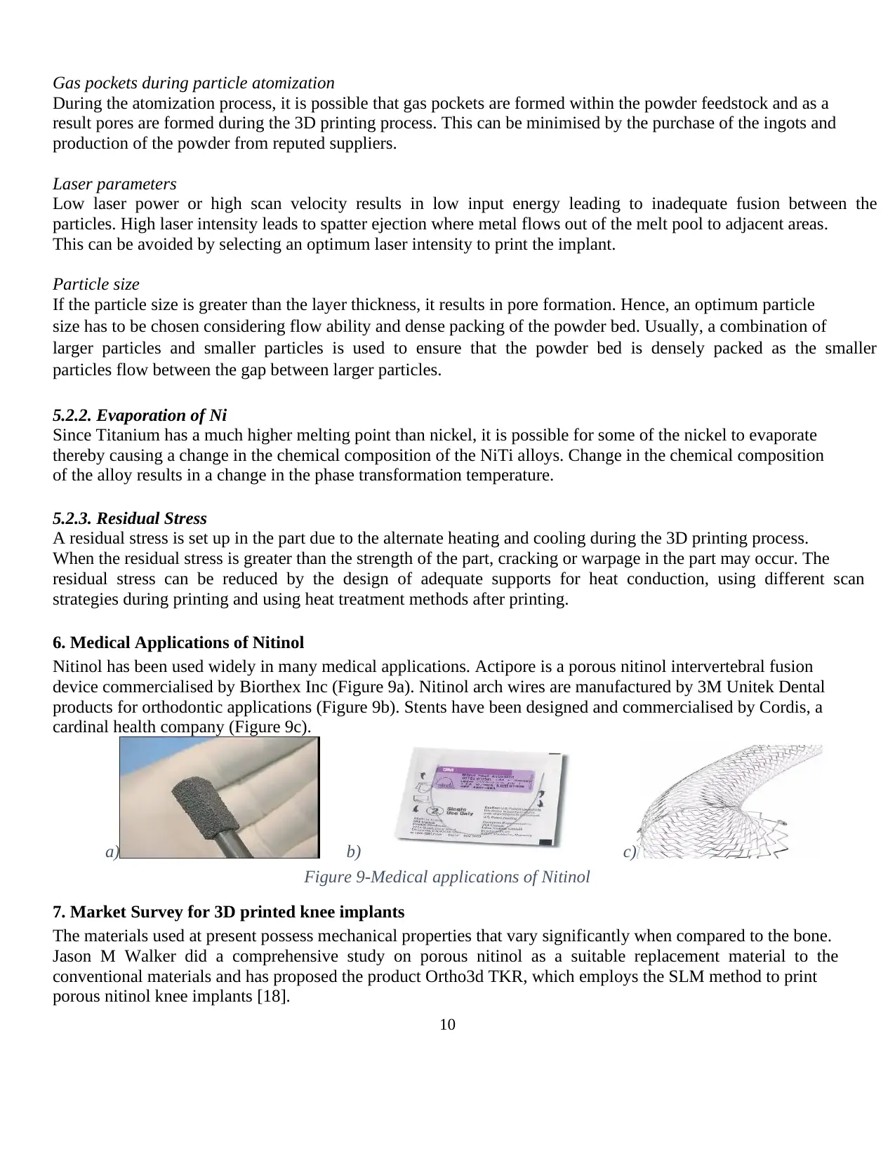
Nitinol has been used widely in many medical applications. Actipore is a porous nitinol intervertebral fusion
device commercialised by Biorthex Inc (Figure 9a). Nitinol arch wires are manufactured by 3M Unitek Dental
products for orthodontic applications (Figure 9b). Stents have been designed and commercialised by Cordis, a
cardinal health company (Figure 9c).
a) b) c)
Figure 9-Medical applications of Nitinol
7. Market Survey for 3D printed knee implants
The materials used at present possess mechanical properties that vary significantly when compared to the bone.
Jason M Walker did a comprehensive study on porous nitinol as a suitable replacement material to the
conventional materials and has proposed the product Ortho3d TKR, which employs the SLM method to print
porous nitinol knee implants [18].
11
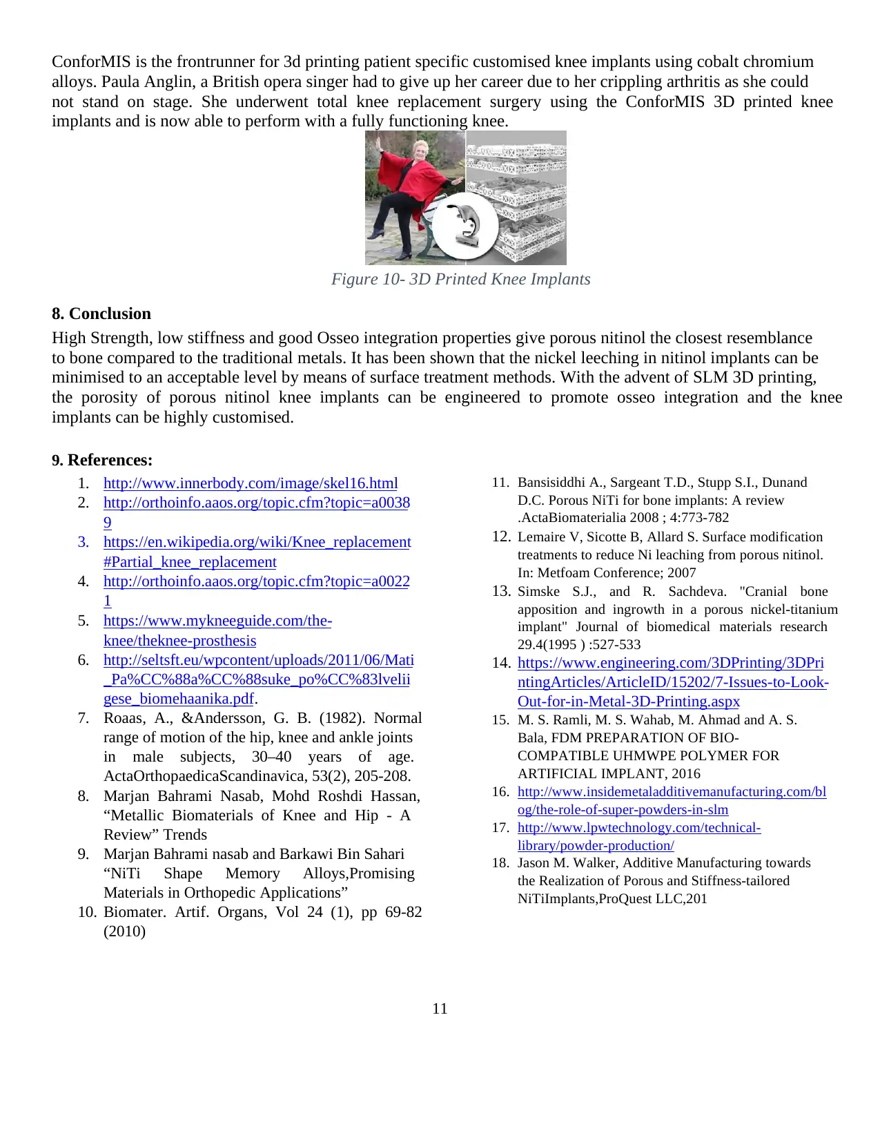
ConforMIS is the frontrunner for 3d printing patient specific customised knee implants using cobalt chromium
alloys. Paula Anglin, a British opera singer had to give up her career due to her crippling arthritis as she could
not stand on stage. She underwent total knee replacement surgery using the ConforMIS 3D printed knee
implants and is now able to perform with a fully functioning knee.
Figure 10- 3D Printed Knee Implants
8. Conclusion
High Strength, low stiffness and good Osseo integration properties give porous nitinol the closest resemblance
to bone compared to the traditional metals. It has been shown that the nickel leeching in nitinol implants can be
minimised to an acceptable level by means of surface treatment methods. With the advent of SLM 3D printing,
the porosity of porous nitinol knee implants can be engineered to promote osseo integration and the knee
implants can be highly customised.
9. References:
1. http://www.innerbody.com/image/skel16.html
2. http://orthoinfo.aaos.org/topic.cfm?topic=a0038
9
3. https://en.wikipedia.org/wiki/Knee_replacement
#Partial_knee_replacement
4. http://orthoinfo.aaos.org/topic.cfm?topic=a0022
1
5. https://www.mykneeguide.com/the-
knee/theknee-prosthesis
6. http://seltsft.eu/wpcontent/uploads/2011/06/Mati
_Pa%CC%88a%CC%88suke_po%CC%83lvelii
gese_biomehaanika.pdf.
7. Roaas, A., &Andersson, G. B. (1982). Normal
range of motion of the hip, knee and ankle joints
in male subjects, 30–40 years of age.
ActaOrthopaedicaScandinavica, 53(2), 205-208.
8. Marjan Bahrami Nasab, Mohd Roshdi Hassan,
“Metallic Biomaterials of Knee and Hip - A
Review” Trends
9. Marjan Bahrami nasab and Barkawi Bin Sahari
“NiTi Shape Memory Alloys,Promising
Materials in Orthopedic Applications”
10. Biomater. Artif. Organs, Vol 24 (1), pp 69-82
(2010)
11. Bansisiddhi A., Sargeant T.D., Stupp S.I., Dunand
D.C. Porous NiTi for bone implants: A review
.ActaBiomaterialia 2008 ; 4:773-782
12. Lemaire V, Sicotte B, Allard S. Surface modification
treatments to reduce Ni leaching from porous nitinol.
In: Metfoam Conference; 2007
13. Simske S.J., and R. Sachdeva. "Cranial bone
apposition and ingrowth in a porous nickel-titanium
implant" Journal of biomedical materials research
29.4(1995 ) :527-533
14. https://www.engineering.com/3DPrinting/3DPri
ntingArticles/ArticleID/15202/7-Issues-to-Look-
Out-for-in-Metal-3D-Printing.aspx
15. M. S. Ramli, M. S. Wahab, M. Ahmad and A. S.
Bala, FDM PREPARATION OF BIO-
COMPATIBLE UHMWPE POLYMER FOR
ARTIFICIAL IMPLANT, 2016
16. http://www.insidemetaladditivemanufacturing.com/bl
og/the-role-of-super-powders-in-slm
17. http://www.lpwtechnology.com/technical-
library/powder-production/
18. Jason M. Walker, Additive Manufacturing towards
the Realization of Porous and Stiffness-tailored
NiTiImplants,ProQuest LLC,201
1 out of 12
Related Documents
Your All-in-One AI-Powered Toolkit for Academic Success.
+13062052269
info@desklib.com
Available 24*7 on WhatsApp / Email
![[object Object]](/_next/static/media/star-bottom.7253800d.svg)
Unlock your academic potential
© 2024 | Zucol Services PVT LTD | All rights reserved.
