Experiment Analysis: Engineering Measurement Lab Report on Circuits
VerifiedAdded on 2023/06/11
|7
|840
|301
AI Summary
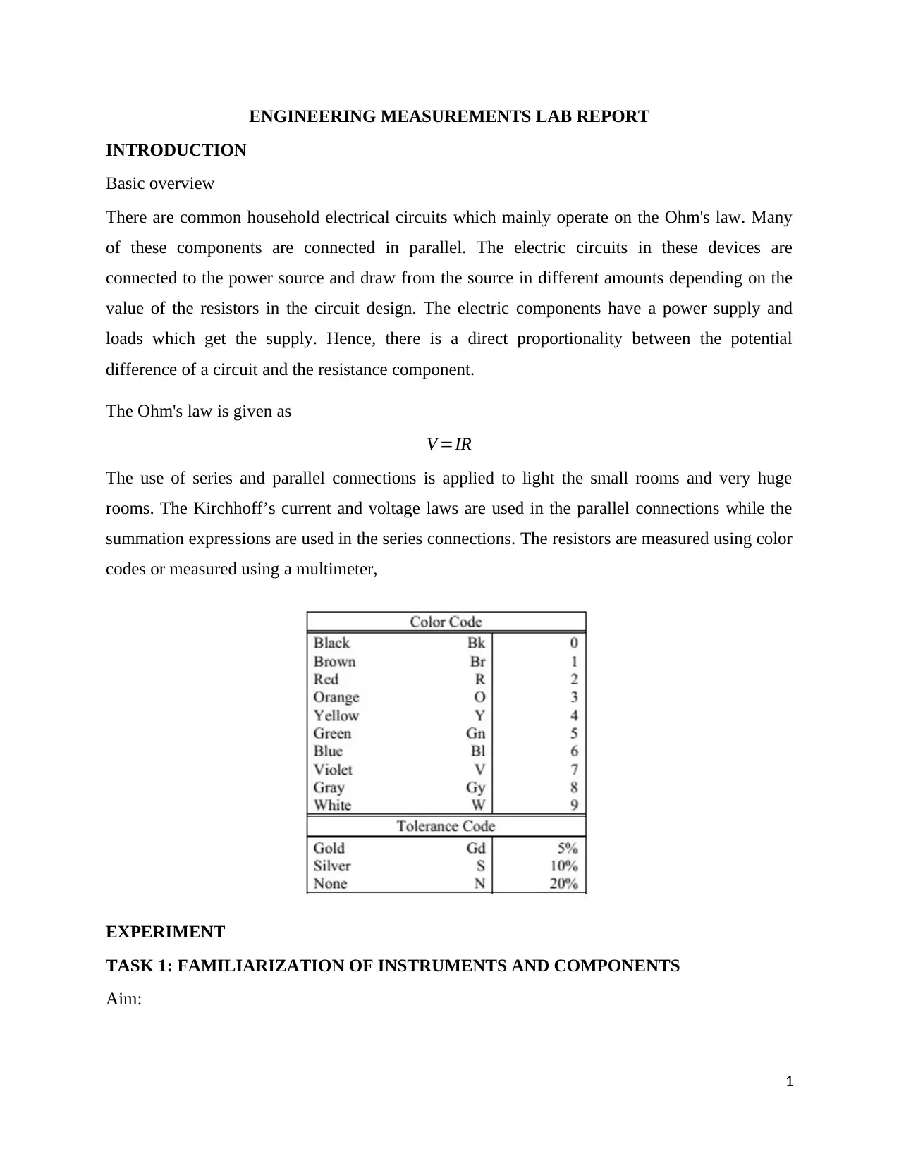
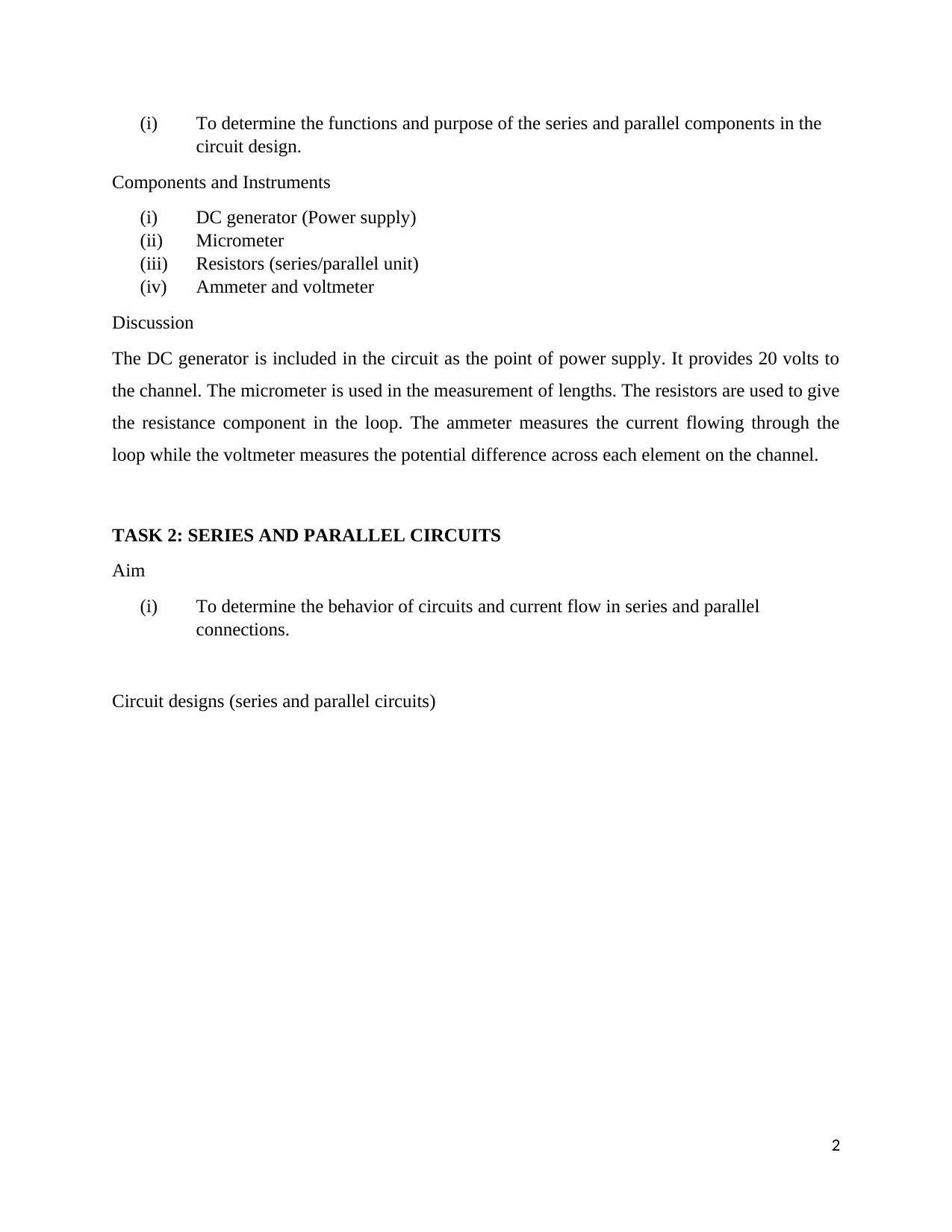
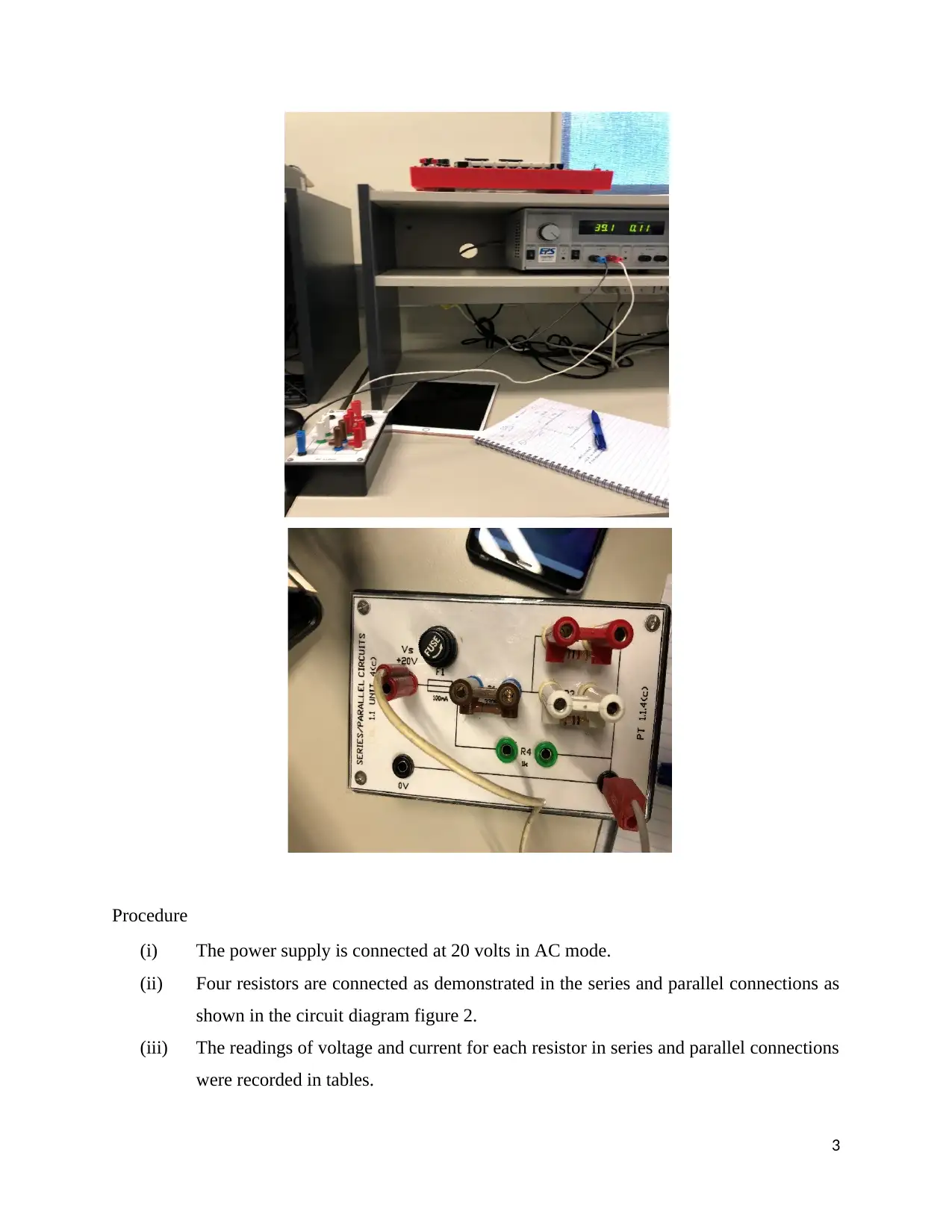
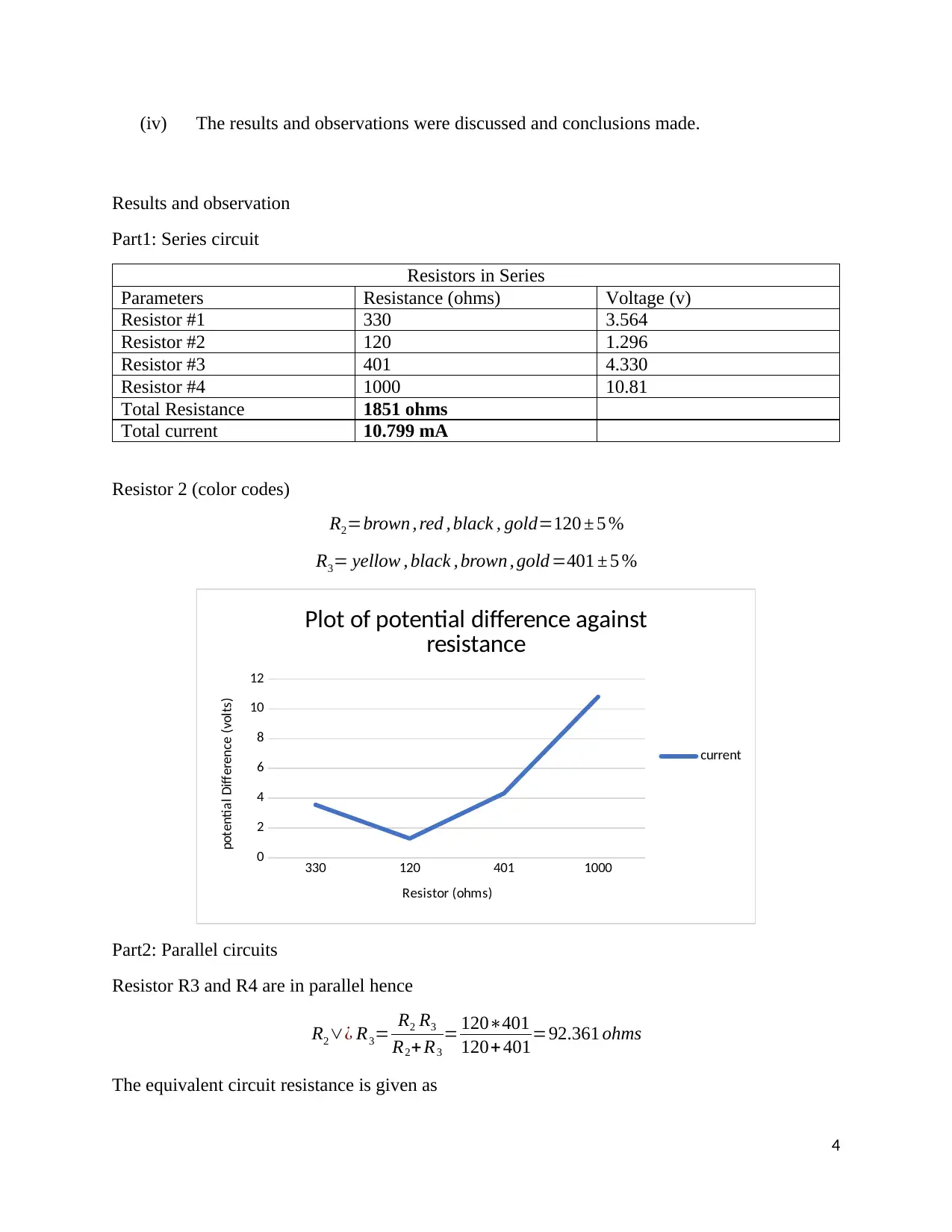
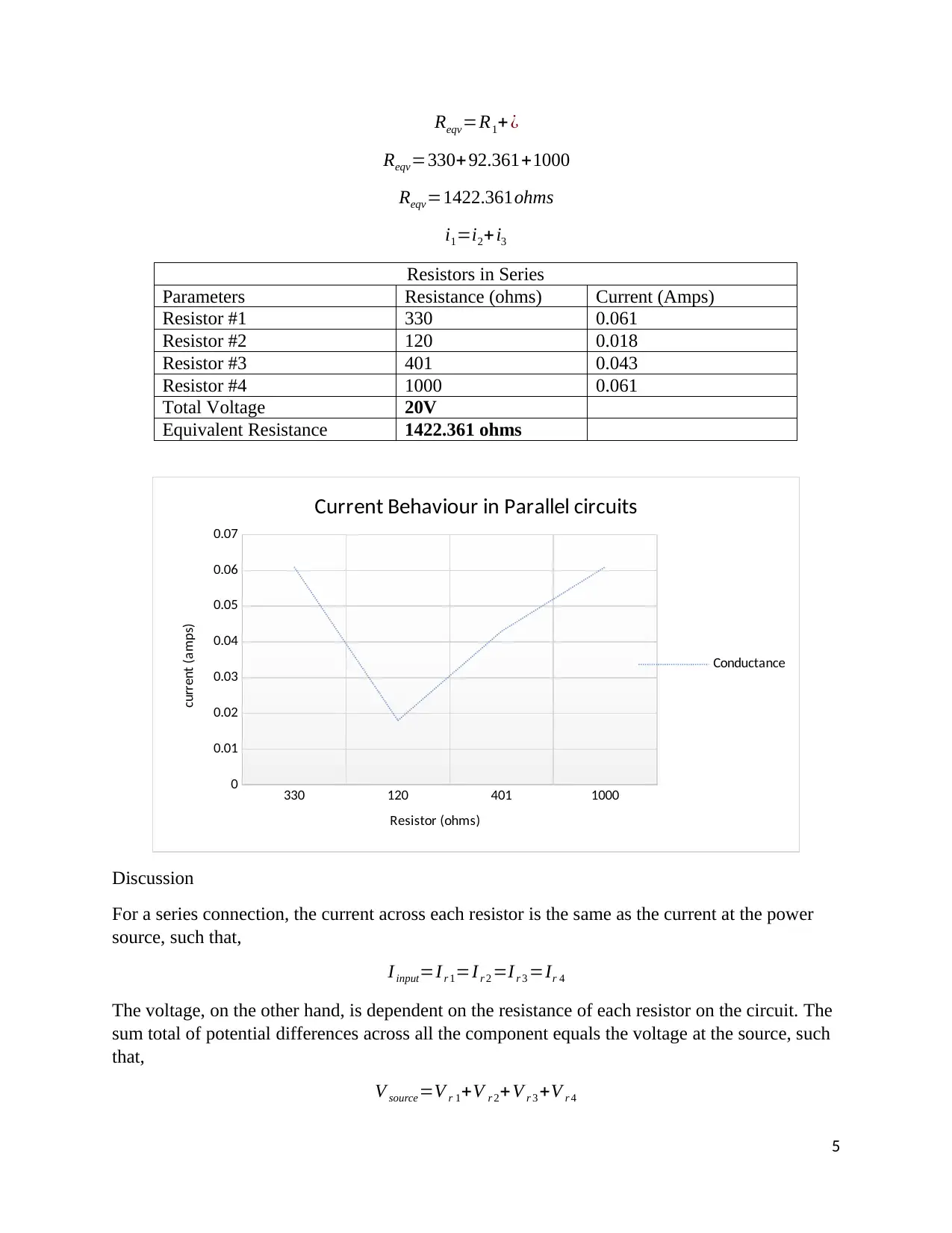
This engineering measurement lab report investigates the behavior of series and parallel circuits, focusing on Ohm's law and Kirchhoff's laws. The experiment involves constructing series and parallel circuit connections with resistors, measuring voltage and current, and analyzing the results. The report details the components and instruments used, including a DC generator, micrometer, resistors, ammeter, and voltmeter. Results are presented in tables and graphs, illustrating the relationships between voltage, current, and resistance in both series and parallel configurations. The discussion highlights the differences in current and voltage distribution between the two circuit types, confirming that current remains constant in series circuits while voltage varies, and vice versa for parallel circuits. The report concludes that series and parallel connections exhibit distinct electrical characteristics, which are validated through experimental observations and the application of fundamental circuit laws. Desklib provides access to similar lab reports and study resources for students.

1 out of 7
Related Documents


Your All-in-One AI-Powered Toolkit for Academic Success.
+13062052269
info@desklib.com
Available 24*7 on WhatsApp / Email
![[object Object]](/_next/static/media/star-bottom.7253800d.svg)
Copyright © 2020–2026 A2Z Services. All Rights Reserved. Developed and managed by ZUCOL.