Driveshaft Design and Analysis: Loading, Material Selection
VerifiedAdded on 2022/09/18
|14
|2338
|36
Report
AI Summary
This report provides a comprehensive analysis of driveshaft design, addressing various aspects such as loading cases, material selection, and manufacturing processes. The report begins by identifying and explaining different loading scenarios that must be considered during the design ...
ENGINEERING MECHANICS
By Name
Course
Instructor
Institution
Location
Date
By Name
Course
Instructor
Institution
Location
Date
Paraphrase This Document
Need a fresh take? Get an instant paraphrase of this document with our AI Paraphraser
INTRODUCTION
Shaft has been considered as a component very vital in every machine and mechanical systems.
Nearly in all transmission of power in the shaft components, the primary part is shaft. Its design
must therefore be as efficient as possible for effective working of the machine. The conventional
procedure of shaft design therefore has its own benefits. The design of shafts is therefore done
for various conditions of loading. The prime causes of failure in the case of the shaft are the
discontinuities since they cause fracture. In most cases especially practical applications, the
design of shaft must be done for the combined loadings (Sim, Moon and Jeon 2018).
RESULTS AND DISCUSSION
Loading cases to be considered during shaft design:
As a rotating member, it provides rotation axis while transmitting power or the motion itself. The
rotating transmission parts have exposure to possibly two types of loading:
Bending from the transverse loads at the sheaves, gears and sprockets.
The next type of load is the torsion due to the torque being transmitted.
The occurrence of these loads usually take place in combination since the toque being
transmitted maybe related to the forces at the teeth of the sprockets, gears all of which are
usually attached to the shaft. Both bending and torque loads may vary with time or be constant. It
is also possible to consider axial loading on the shaft (SoltanRezaee, et al.2018). This is because
is because its occurrence will be dependent on the coupling or joining arrangement of the shaft
for example when coupling is done by the use of the helical or worm gear. Although it can be
neglected but its consideration will give more accurate design of shaft.
Material for tube section
In order for the tube to effectively perform its functions, it must meet the following
requirements:
Very good properties of welding
Higher durability and torsional strength
High accuracy in terms of geometry. This extends to roundness and eccentricity
Excellent condition of the surface
High values of strength (Gong et al.2018).
In order for the above requirements to be met, a tough material preferably Aluminium Alloy is
chosen. This is because it is known to exhibit good weldability, light weight and well s resistance
to corrosion.
Stress transformation and rupture
Through transformation effects, stress rupture will take place at the end of tertiary creep stage.
This implies that through transformation of stress, the tube’s load carrying capacity will drop to
the level of applied stress hence leading to the failure. The torsional stress transformation will
therefore cause fracture to occur diagonally (Wotzak 2017).
Calculations
Parameters given;
A torque of 1100 N.m
Diameter of 42 mm
The material used yield stress of is 450 MPa.
⊘ This is a preview!⊘
Do you want full access?
Subscribe today to unlock all pages.

Trusted by 1+ million students worldwide
Part I
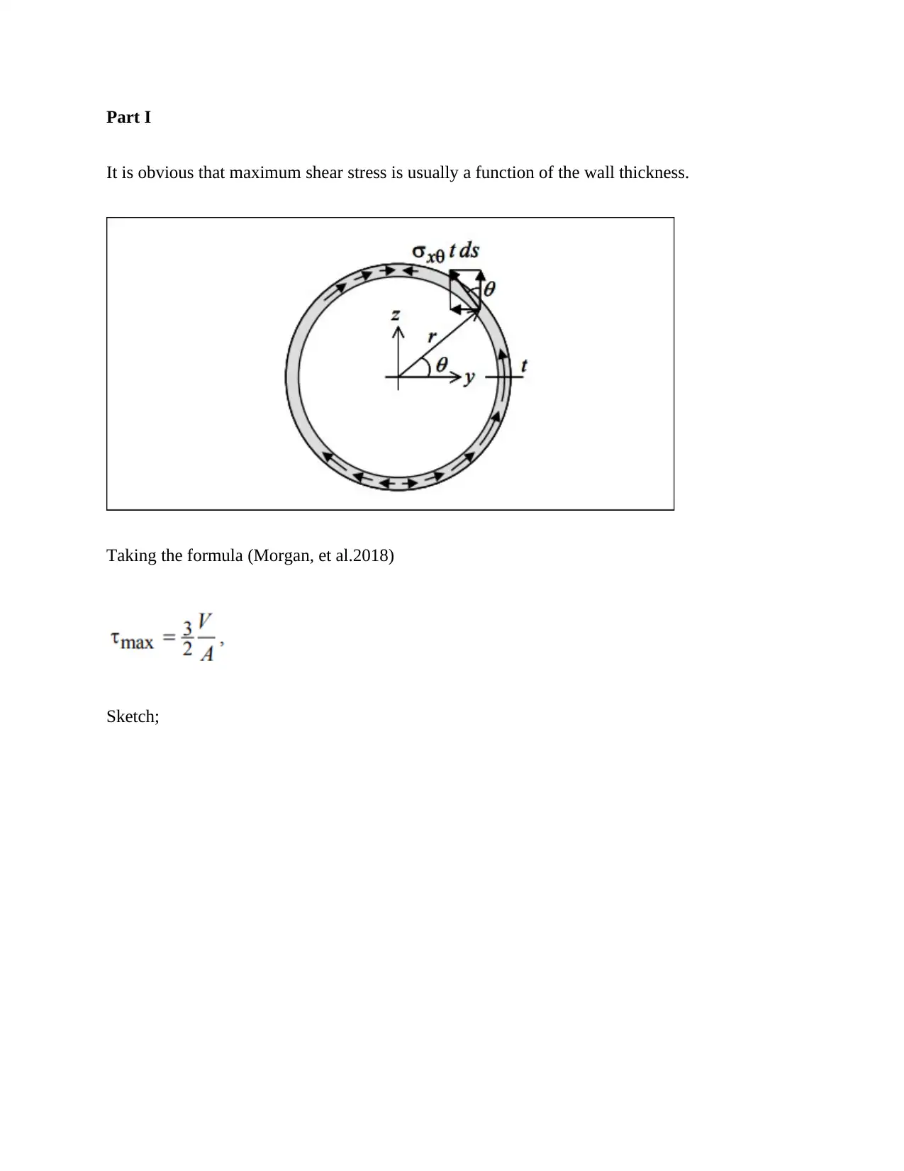
It is obvious that maximum shear stress is usually a function of the wall thickness.
Taking the formula (Morgan, et al.2018)
Sketch;
It is obvious that maximum shear stress is usually a function of the wall thickness.
Taking the formula (Morgan, et al.2018)
Sketch;
Paraphrase This Document
Need a fresh take? Get an instant paraphrase of this document with our AI Paraphraser
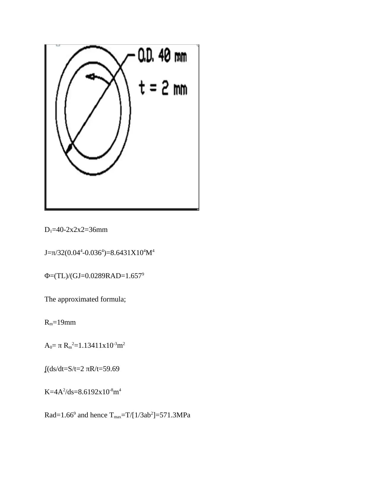
D1=40-2x2x2=36mm
J=π/32(0.044-0.0364)=8.6431X104M4
Φ=(TL)/(GJ=0.0289RAD=1.6579
The approximated formula;
Rm=19mm
A0= π Rm2=1.13411x10⁻³m2
ʆ(ds/dt=S/t=2 πR/t=59.69
K=4A2/ds=8.6192x10-8m4
Rad=1.669 and hence Tmax=T/[1/3ab2]=571.3MPa
J=π/32(0.044-0.0364)=8.6431X104M4
Φ=(TL)/(GJ=0.0289RAD=1.6579
The approximated formula;
Rm=19mm
A0= π Rm2=1.13411x10⁻³m2
ʆ(ds/dt=S/t=2 πR/t=59.69
K=4A2/ds=8.6192x10-8m4
Rad=1.669 and hence Tmax=T/[1/3ab2]=571.3MPa
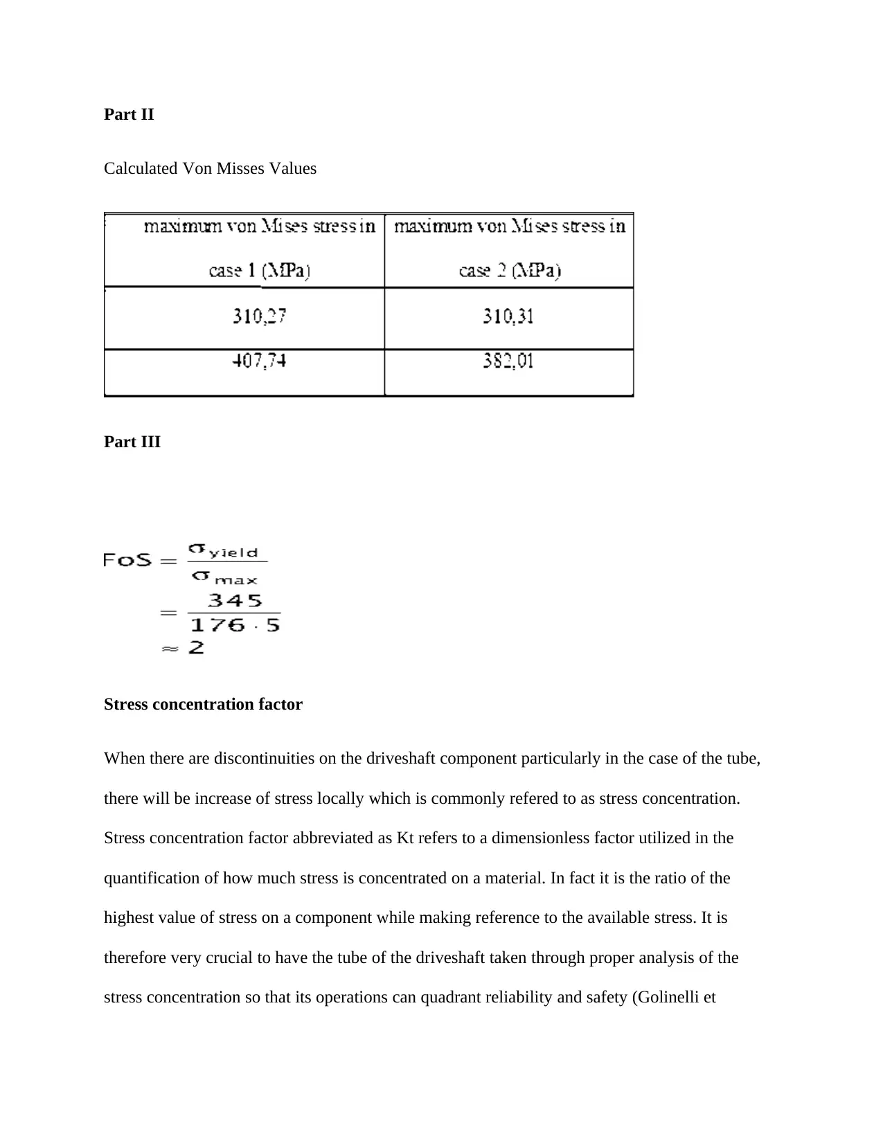
Part II
Calculated Von Misses Values
Part III
Stress concentration factor
When there are discontinuities on the driveshaft component particularly in the case of the tube,
there will be increase of stress locally which is commonly refered to as stress concentration.
Stress concentration factor abbreviated as Kt refers to a dimensionless factor utilized in the
quantification of how much stress is concentrated on a material. In fact it is the ratio of the
highest value of stress on a component while making reference to the available stress. It is
therefore very crucial to have the tube of the driveshaft taken through proper analysis of the
stress concentration so that its operations can quadrant reliability and safety (Golinelli et
⊘ This is a preview!⊘
Do you want full access?
Subscribe today to unlock all pages.

Trusted by 1+ million students worldwide
al.2018). In case the operation of stress concentration analysis in not done, there likelihood that
the manufactured component will not function fully with the load and this will consequently
affect the system’s balance (Nayak et al.2018).
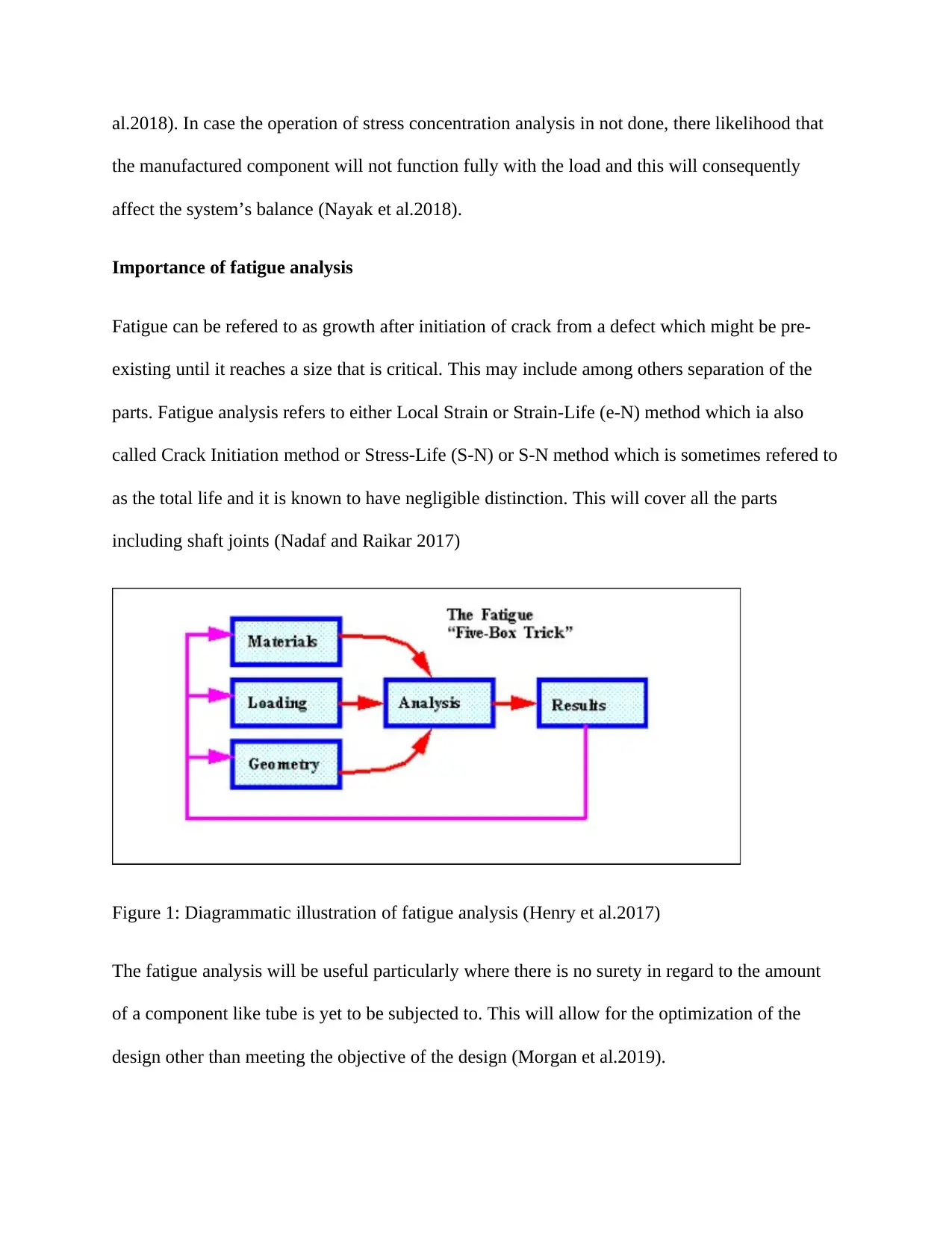
Importance of fatigue analysis
Fatigue can be refered to as growth after initiation of crack from a defect which might be pre-
existing until it reaches a size that is critical. This may include among others separation of the
parts. Fatigue analysis refers to either Local Strain or Strain-Life (e-N) method which ia also
called Crack Initiation method or Stress-Life (S-N) or S-N method which is sometimes refered to
as the total life and it is known to have negligible distinction. This will cover all the parts
including shaft joints (Nadaf and Raikar 2017)
Figure 1: Diagrammatic illustration of fatigue analysis (Henry et al.2017)
The fatigue analysis will be useful particularly where there is no surety in regard to the amount
of a component like tube is yet to be subjected to. This will allow for the optimization of the
design other than meeting the objective of the design (Morgan et al.2019).
Paraphrase This Document
Need a fresh take? Get an instant paraphrase of this document with our AI Paraphraser
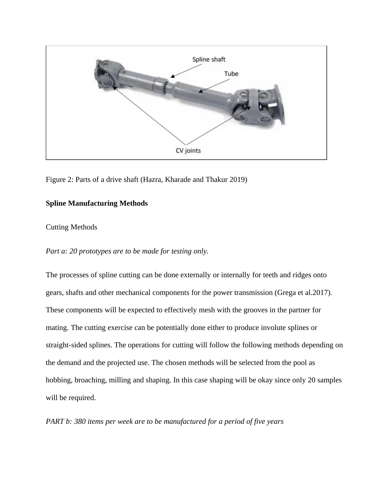
Figure 2: Parts of a drive shaft (Hazra, Kharade and Thakur 2019)
Spline Manufacturing Methods
Cutting Methods
Part a: 20 prototypes are to be made for testing only.
The processes of spline cutting can be done externally or internally for teeth and ridges onto
gears, shafts and other mechanical components for the power transmission (Grega et al.2017).
These components will be expected to effectively mesh with the grooves in the partner for
mating. The cutting exercise can be potentially done either to produce involute splines or
straight-sided splines. The operations for cutting will follow the following methods depending on
the demand and the projected use. The chosen methods will be selected from the pool as
hobbing, broaching, milling and shaping. In this case shaping will be okay since only 20 samples
will be required.
PART b: 380 items per week are to be manufactured for a period of five years
It is important to note that the production of the prototypes will be basically used for the
purposes of testing. This implies that in the case of mass production, rapid methods will be most
appropriate. Broaching has been identified as one of the machining operations which forms
contour rapidly on the workpiece through movement of the cutter (Ballo et al.2020). The cutter is
called a broach. The broach is known to have a series of teeth which will gradually increase in
height.
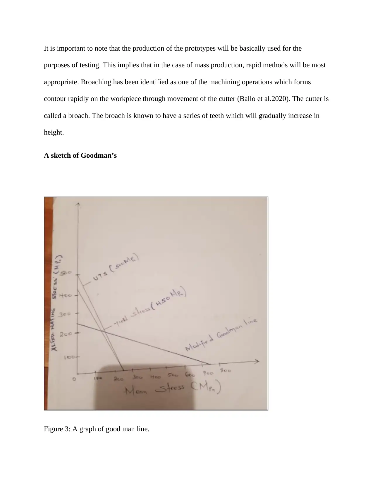
A sketch of Goodman’s
Figure 3: A graph of good man line.
⊘ This is a preview!⊘
Do you want full access?
Subscribe today to unlock all pages.

Trusted by 1+ million students worldwide
Sustained damages by the U-joints
In most of the cases, noises which emanate from under the car may not be as a result of the
driveshaft of the car or even the propeller shaft upon being examined closely. In the event that
the source happens to be the universal joint or U-joint, then it should be regarded as very serious
problem. It is this particular joint which allows for the backward and forward movement of the
car. This implies that such a car must be engaged with parking brake before it is shifted to the
neutral when parked. Having access to the universal joint will mean raising it. The joint will be
rocked just to see or check on the flexibility without incurring movement excessively.
Part of the solution to this particular problem may include checking for the presence of rust on
the bearing seat cap which usually functions to cover the U-joint. This might be either for the
case of the minor driveshaft or main drive shaft. The problem can thus be fixed as soon as
possible.
Worn Out driveshaft
Provided the driveshaft is in proper condition or the propeller itself so as to perform the activities
of power transfer from perceived differential, it should never be assumed. The worn out
driveshaft should be replaced immediately.
A high pitch squeaking noise
This is the defect effect heard through a noise generation. It can be experienced whether the car
is on motion or stationary. In order to have this particular defect managed, lubing up of the parts
of the shaft as well as its components will be effective. The boots will be removed just to see if
the parts needs proper lubrication exercise so that it can be kept running for a longer time.
Paraphrase This Document
Need a fresh take? Get an instant paraphrase of this document with our AI Paraphraser
Keeping all the parts which are in motion properly-lubed will be very crucial as far as reduction
of tear and wear is concerned (AKKAS et al 2019).
CONCLUSION
The report has effectively captured the concept of shaft design, analysis of failure as well as
fatigue and fracture. The design was subject to varying loading while adopting modern and
conventional procedures of the design. Fatigue and fracture when considered could be combined
for effective application particularly in the case of factor of safety determination. From the
design analysis, it became evident that failure analysis assist in the identification of the
discontinuities which always act as the locations of stress concentration. The initiation of the
crack was found to be taken place at the key way which with time undergoes propagation. Above
all, it was discovered that the essential loading in the case of the shafts is torsional. The design pf
the haft must therefore considered the application of the shear stresses.
REFERENCES
AKKAS, O., Efe, I.S.I.K., TARAKCI, S. and KASABA, M., 2019. A Correlation Study of an
FEA Method Developed for Heavy Duty Driveshaft Applications. The Eurasia Proceedings of
Science Technology Engineering and Mathematics, 7, pp.315-320.
Ballo, F., Gobbi, M., Mastinu, G. and Previati, G., 2020. Thin-walled tubes under torsion: multi-
objective optimal design. Optimization and Engineering, 21(1), pp.1-24.
Bhardwaj, K., Gavrilovska, A., Steiner, M., Flack, M. and Ludin, S., 2018. DRIVESHAFT:
Improving Perceived Mobile Web Performance. arXiv preprint arXiv:1809.09292.
Golinelli, N., Spaggiari, A., Castagnetti, D., Fornari, L., Dragoni, E., Gualdi, G. and Brunazzi,
A., 2019. Development of a driveshaft torque transducer for low-cost structural health
⊘ This is a preview!⊘
Do you want full access?
Subscribe today to unlock all pages.

Trusted by 1+ million students worldwide
monitoring of off-highway vehicles. Proceedings of the Institution of Mechanical Engineers,
Part L: Journal of Materials: Design and Applications, 233(4), pp.714-720.
Gong, L., Gao, X., Yang, H., Liu, Y. and Yao, X., 2018. Design on the driveshaft of 3D 4-
Directional carbon fiber braided composites. Composite Structures, 203, pp.466-473.
Grega, R., Krajňák, J., Žuľová, L., Fedorko, G. and Molnár, V., 2017. Failure analysis of
driveshaft of truck body caused by vibrations. Engineering Failure Analysis, 79, pp.208-215.
Hazra, S., Kharade, A. and Thakur, S., 2019. Diagnosis and Elimination of Vehicle Lateral
Shake in Passenger Car through Modification of Driveshaft Joints and Engine Mount
System (No. 2019-26-0214). SAE Technical Paper.
Henry, T.C., Riddick, J.C., Mills, B.T. and Habtour, E.M., 2017. Composite driveshaft prototype
design and survivability testing. Journal of composite materials, 51(16), pp.2377-2386.
Morgan, J., Miller, L.J., Titkemeyer, R.W. and Kilcoin, C., Teleflex Medical Devices SARL,
2018. Powered driver actuated by force on driveshaft and related kits, components, and
methods. U.S. Patent 10,092,320.
Morgan, J., Miller, L.J., Titkemeyer, R.W. and Kilcoin, C., Teleflex Medical Devices SARL,
2019. Powered driver actuated by force on driveshaft and related kits, components, and
methods. U.S. Patent Application 16/135,161.
Nadaf, A.R. and Raikar, V., 2017. Design & analysis of composite shaft of passenger
vehicle. International research journal of engineering and technology, 4(8), pp.151-158.
Paraphrase This Document
Need a fresh take? Get an instant paraphrase of this document with our AI Paraphraser
Nayak, S.Y., Amin, N.M., Heckadka, S.S., Shenoy, V., Prakash, C.S. and Mabbu, R., 2018.
Design, fabrication and testing of carbon fiber reinforced epoxy drive shaft for all terrain vehicle
using filament winding. In MATEC Web of Conferences (Vol. 153, p. 04010). EDP Sciences.
Selsam, D.S., 2016. Stationary co-axial multi-rotor wind turbine supported by continuous
central driveshaft. U.S. Patent 9,249,783.
Sim, K.J., Moon, H.J. and Jeon, N., 2018. A Study on the Development of the Driveshaft for a
3.5-Ton Commercial Vehicle. Journal of the Korean Society of Manufacturing Process
Engineers, 17(2), pp.153-159.
SoltanRezaee, M., Ghazavi, M.R., Najafi, A. and Rahmanian, S., 2018. Stability of a multi-body
driveshaft system excited through U-joints. Meccanica, 53(4-5), pp.1167-1183.
Wotzak, M.G., General Electric Co, 2017. Aircraft engine driveshaft vessel assembly and method
of assembling the same. U.S. Patent 9,657,646.
1 out of 14
Your All-in-One AI-Powered Toolkit for Academic Success.
+13062052269
info@desklib.com
Available 24*7 on WhatsApp / Email
![[object Object]](/_next/static/media/star-bottom.7253800d.svg)
Unlock your academic potential
© 2024 | Zucol Services PVT LTD | All rights reserved.