ProductsLogo
LogoStudy Documents
LogoAI Grader
LogoAI Answer
LogoAI Code Checker
LogoPlagiarism Checker
LogoAI Paraphraser
LogoAI Quiz
LogoAI Detector
PricingBlogAbout Us
logo

Mechanical Principles Forces and Reactions

Verified

Added on  2019/09/19

|3
|374
|439
Project
AI Summary
The assignment is about solving mechanical engineering problems. Students are required to solve two problems, P1 and M1, where they need to determine the forces and reactions in a plane pin-jointed frame subjected to vertical loads. Additionally, students also have to solve problem P2 which involves calculating reactions, shear force, and bending moment of a uniform horizontal beam with various forces acting on it. Finally, students are required to solve problem M2 which is about a light beam ABCD that is simply supported at points A and B, and carrying a uniformly distributed load and point loads.

Contribute Materials

Your contribution can guide someone’s learning journey. Share your documents today.
Document Page
Engineering
Programme : National Diploma in Engineering
Year 2
Unit : Further Mechanical Principles
Assignment 1
P1/M1
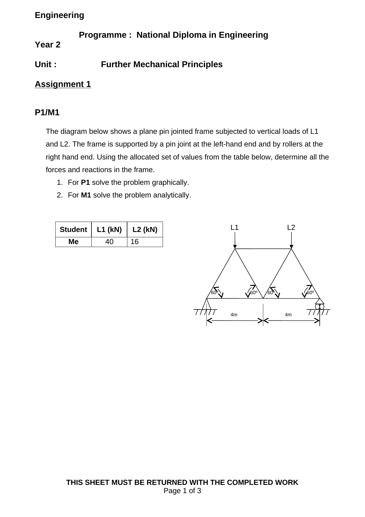
The diagram below shows a plane pin jointed frame subjected to vertical loads of L1
and L2. The frame is supported by a pin joint at the left-hand end and by rollers at the
right hand end. Using the allocated set of values from the table below, determine all the
forces and reactions in the frame.
1. For P1 solve the problem graphically.
2. For M1 solve the problem analytically.
Student L1 (kN) L2 (kN)
Me 40 16
THIS SHEET MUST BE RETURNED WITH THE COMPLETED WORK
Page 1 of 3
L1 L2
60º 60º 60º 60º
4m 4m

Secure Best Marks with AI Grader

Need help grading? Try our AI Grader for instant feedback on your assignments.
Document Page
P2
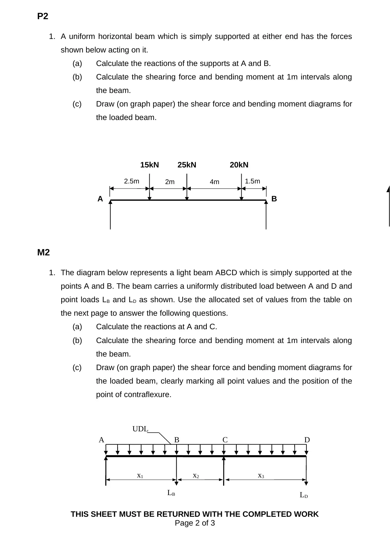
1. A uniform horizontal beam which is simply supported at either end has the forces
shown below acting on it.
(a) Calculate the reactions of the supports at A and B.
(b) Calculate the shearing force and bending moment at 1m intervals along
the beam.
(c) Draw (on graph paper) the shear force and bending moment diagrams for
the loaded beam.
M2
1. The diagram below represents a light beam ABCD which is simply supported at the
points A and B. The beam carries a uniformly distributed load between A and D and
point loads LB and LD as shown. Use the allocated set of values from the table on
the next page to answer the following questions.
(a) Calculate the reactions at A and C.
(b) Calculate the shearing force and bending moment at 1m intervals along
the beam.
(c) Draw (on graph paper) the shear force and bending moment diagrams for
the loaded beam, clearly marking all point values and the position of the
point of contraflexure.
THIS SHEET MUST BE RETURNED WITH THE COMPLETED WORK
Page 2 of 3
UDL
LD
x1
A C
x2
LB
x3
DB
15kN 20kN
2.5m 4m
A B
2m
25kN
1.5m
Document Page
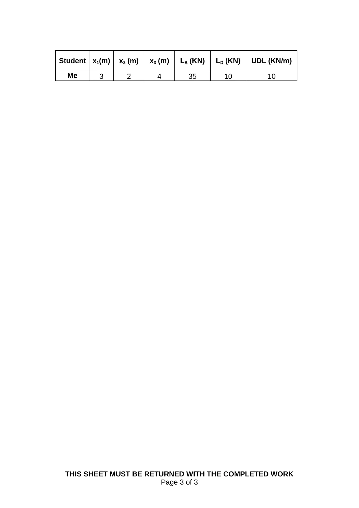
Student x1(m) x2 (m) x3 (m) LB (KN) LD (KN) UDL (KN/m)
Me 3 2 4 35 10 10
THIS SHEET MUST BE RETURNED WITH THE COMPLETED WORK
Page 3 of 3
1 out of 3
[object Object]

Your All-in-One AI-Powered Toolkit for Academic Success.

Available 24*7 on WhatsApp / Email

[object Object]