Engineering Science Report: Material Testing, Deflection & Analysis
VerifiedAdded on 2023/06/03
|13
|1967
|406
Report
AI Summary
This Engineering Science report provides a comprehensive overview of material testing methods, focusing on metallurgical and mechanical testing. Metallurgical testing involves analyzing a material's properties, including grain size, chemical composition, and microstructure, with applications in concrete testing, strength evaluation, and elasticity assessment. Mechanical testing determines various material properties through methods like tensile, creep, fatigue, and impact testing, finding applications in automotive, construction, electrical, and packaging industries. The report includes a deflection analysis of steel and aluminum under different loads, comparing theoretical and experimental results with graphical representations and slope calculations to validate the accuracy of the practical experiment. Desklib is a platform where you can find past papers and solved assignments for students.
Engineering Science 1
Engineering science
By Name
Course
Instructor
Institution
Location
Date
Engineering science
By Name
Course
Instructor
Institution
Location
Date
Paraphrase This Document
Need a fresh take? Get an instant paraphrase of this document with our AI Paraphraser
Engineering Science 2
Part 1
Stress is a force per unit area of a material, its unit is Pascal noted a `´ Pa``
The strain is a ratio of extension to the original length, therefore, this parameter has no units.
Young’s Modulus of Elasticity is a constant of stress over strain and its unit is Pascal (pa) (Davis, 2014).
Part 2
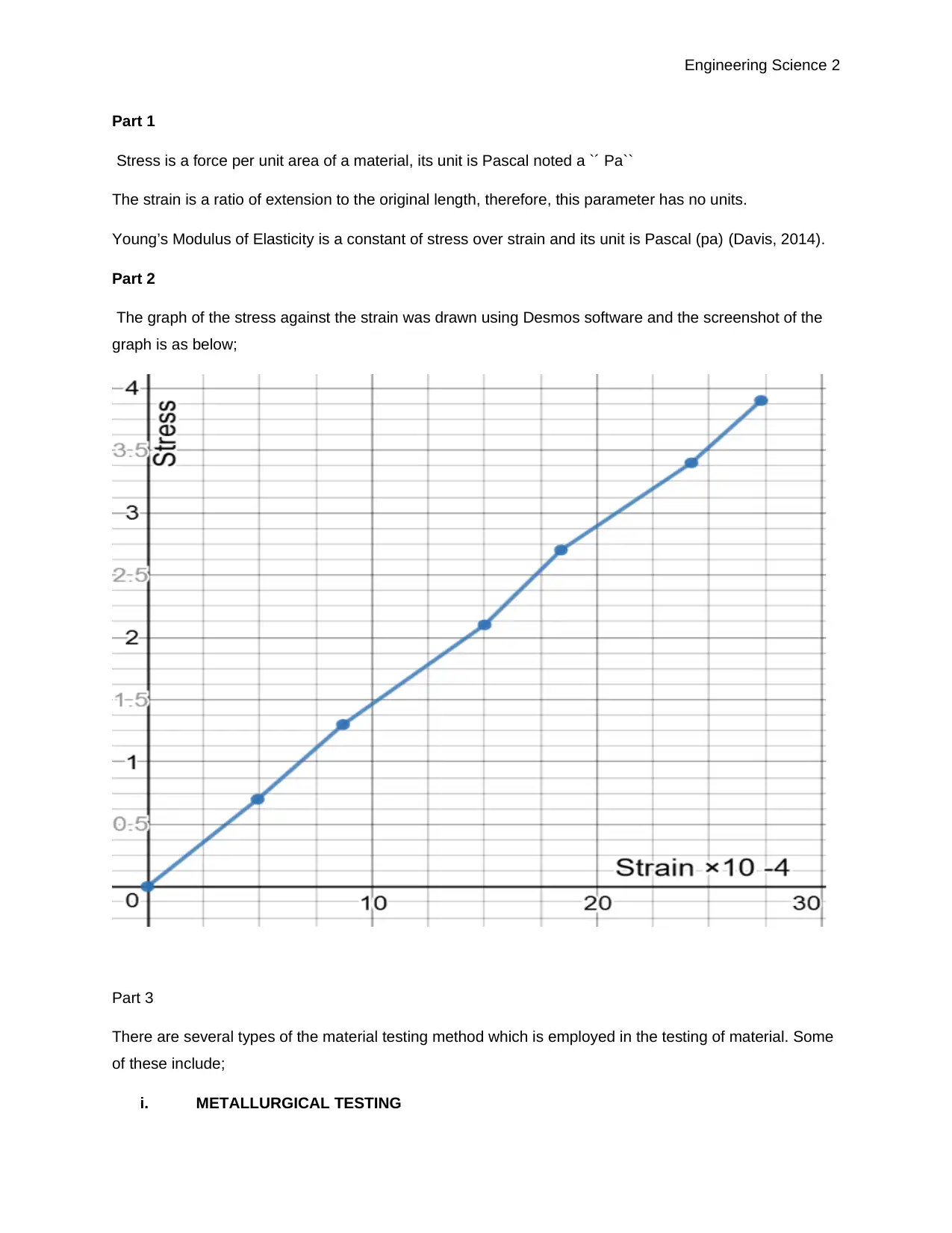
The graph of the stress against the strain was drawn using Desmos software and the screenshot of the
graph is as below;
Part 3
There are several types of the material testing method which is employed in the testing of material. Some
of these include;
i. METALLURGICAL TESTING
Engineering Science 3
ii. MECHANICAL TESTING
i. METALLURGICAL TESTING
This is a testing method which is employed in virtually in every and covers a large range of services,
this method of testing ranges from grain size analysis of material to fractography (Utilization, 2014). This
method testing concentrates quantifying the metal's properties together with chemical analysis and
mechanical testing. This method is always employed to obtain the type of material, size of the grain,
grade and to offer certification for the modern material, failure analysis and microstructure analysis. This
testing method requires technology to test for both advance alloy and traditional metals. Most of these
testing are conducted on on-site. Since this method is employed in the evaluation on the below core
parameter include hardness, grain size, tensile strength, therefore, this type of testing has several real-life
application. Some of these real-life applications include the following;
i. Concrete testing. This type of material is employed in ceramics testing to evaluate the
amount and sizes of the porous contained in the concrete. In most cases, such testing is
done in materials like RCC ( reinforced concrete).
ii. Evaluation of strength in materials. The evaluation of hardness of the material is employed
in real life in rods employed construction of a tall building to help the structure remains very
strong. These metal are basically made of iron because irons are always stronger than other
metals like copper.
iii. Evaluation of elasticity. This method of testing is always applied in obtaining the elasticity of
the steel bars used in the construction of the bridge which is given a space of expansion,
therefore, the material employed should be able to expand.
The below are some of the test procedure for the METALLURGICAL TESTING;
i. Field metallography
ii. Structure examinations
iii. Scanning electron microscopy as well as EDX measurements
iv. Damage analysis
v. Process testing
vi. Layer thickness gauging
vii. Intercrystalline corrosion testing.
⊘ This is a preview!⊘
Do you want full access?
Subscribe today to unlock all pages.

Trusted by 1+ million students worldwide
Engineering Science 4
ii. MECHANICAL TESTING
Mechanical testing is done to produce data which may be employed for the purposes of design.
Basically, this type of testing is a wide testing which always determines different material properties.
Some of these types of testing include the following;
i. Textile testing
ii. Creep testing
iii. Fatigue testing
iv. Impact testing
There are several real-life applications of the mechanical testing method employed in several industries.
These include the following;
i. Quality evaluation via tensile testing of the fitting in an automotive company. The testing is
conducted in carpets, dashboard, airbags, mirrors, bumper, door among other parts.
ii. In the construction industry this mechanical testing can be employed in adhesives testing
strength, mastics, the bond between foam layers and brick (Budynas, 2011).
iii. In electrical and electronic engineering, the mechanical testing is applied in PCB material
tensile strength, component PCB pull off-pull-to forces (Baas, 2014).
iv. In packaging firm, elongation packaging plastic materials, forces related to opening snap-
caps and peel/adhesive of the labels and seals of the containers.
v. In rubber and plastic and rubbers firms, joint strength of plastic interlocking components and
evaluation of the of material tensile nature.
The below are the procedure when conducting the mechanical test ( tensile test);
i. The specimen employed are carefully chosen to ensure that the selected specimen should
not have any crack or notch from the manufacturing firm.
ii. Before the specimen is loaded in the instrument for measuring, a computer or laptop is
connected to the instrument through keying the essential information of the width and a
gauge length of the specimen. The laptop was made to record information and display a
graph of the load-deflection (James Whitney, 2014).
iii. The specimen was then put on the Instron machine then the tensile test was conducted. The
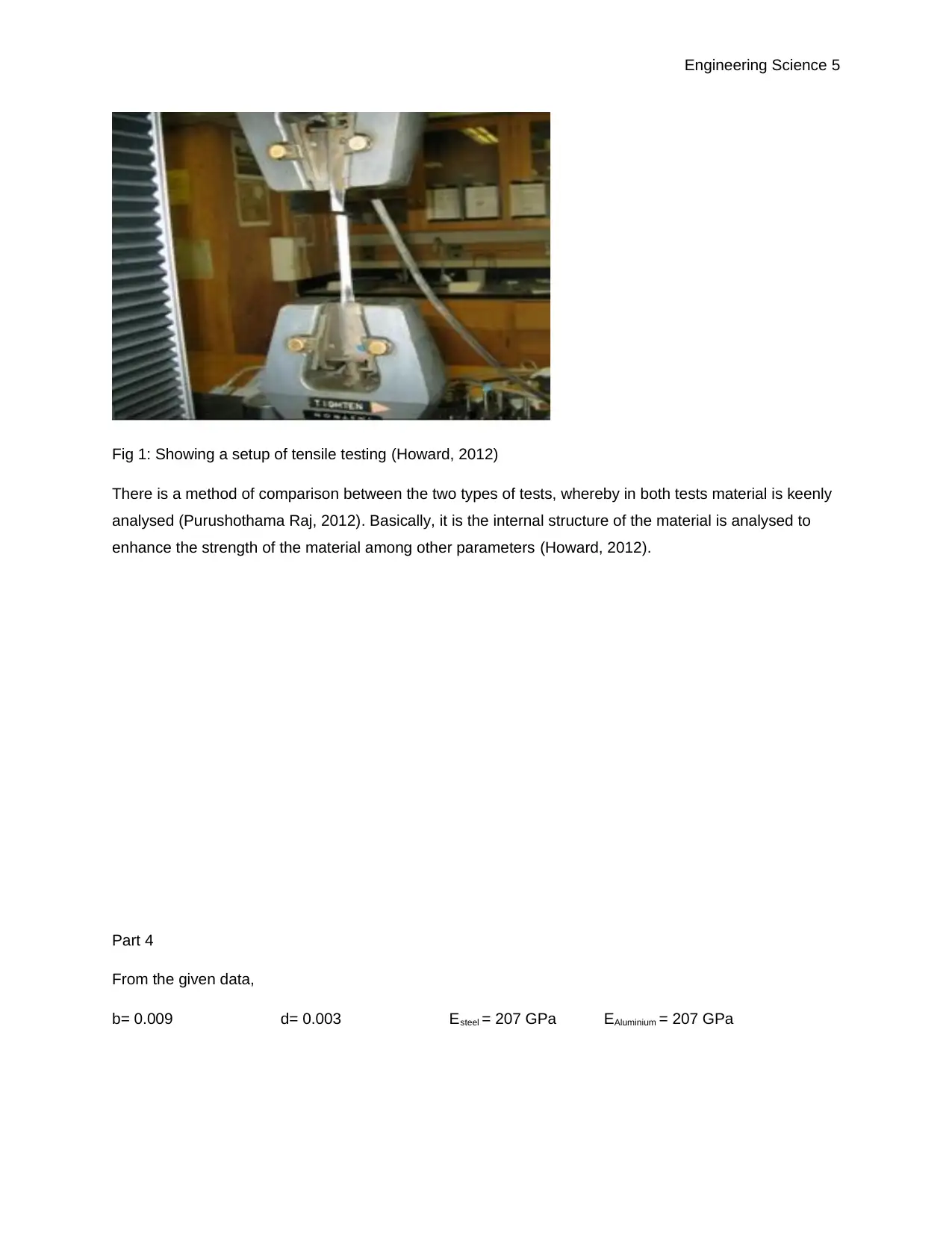
whole procedure setup is illustrated using the following diagram;
Paraphrase This Document
Need a fresh take? Get an instant paraphrase of this document with our AI Paraphraser
Engineering Science 5
Fig 1: Showing a setup of tensile testing (Howard, 2012)
There is a method of comparison between the two types of tests, whereby in both tests material is keenly
analysed (Purushothama Raj, 2012). Basically, it is the internal structure of the material is analysed to
enhance the strength of the material among other parameters (Howard, 2012).
Part 4
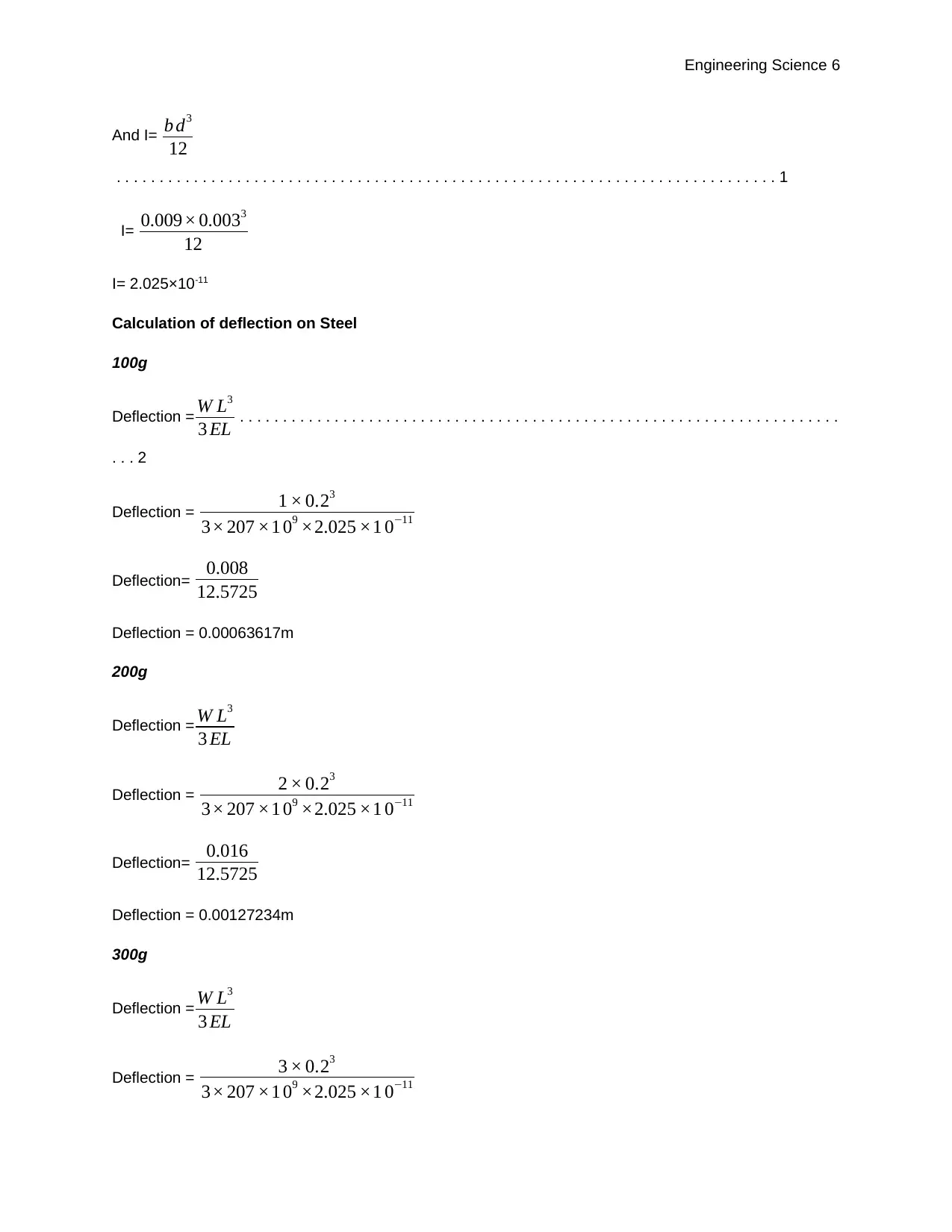
From the given data,
b= 0.009 d= 0.003 Esteel = 207 GPa EAluminium = 207 GPa
Engineering Science 6
And I= b d3
12
. . . . . . . . . . . . . . . . . . . . . . . . . . . . . . . . . . . . . . . . . . . . . . . . . . . . . . . . . . . . . . . . . . . . . . . . . . . . . 1
I= 0.009× 0.0033
12
I= 2.025×10⁻¹¹
Calculation of deflection on Steel
100g
Deflection = W L3
3 EL . . . . . . . . . . . . . . . . . . . . . . . . . . . . . . . . . . . . . . . . . . . . . . . . . . . . . . . . . . . . . . . . . . . . . .
. . . 2
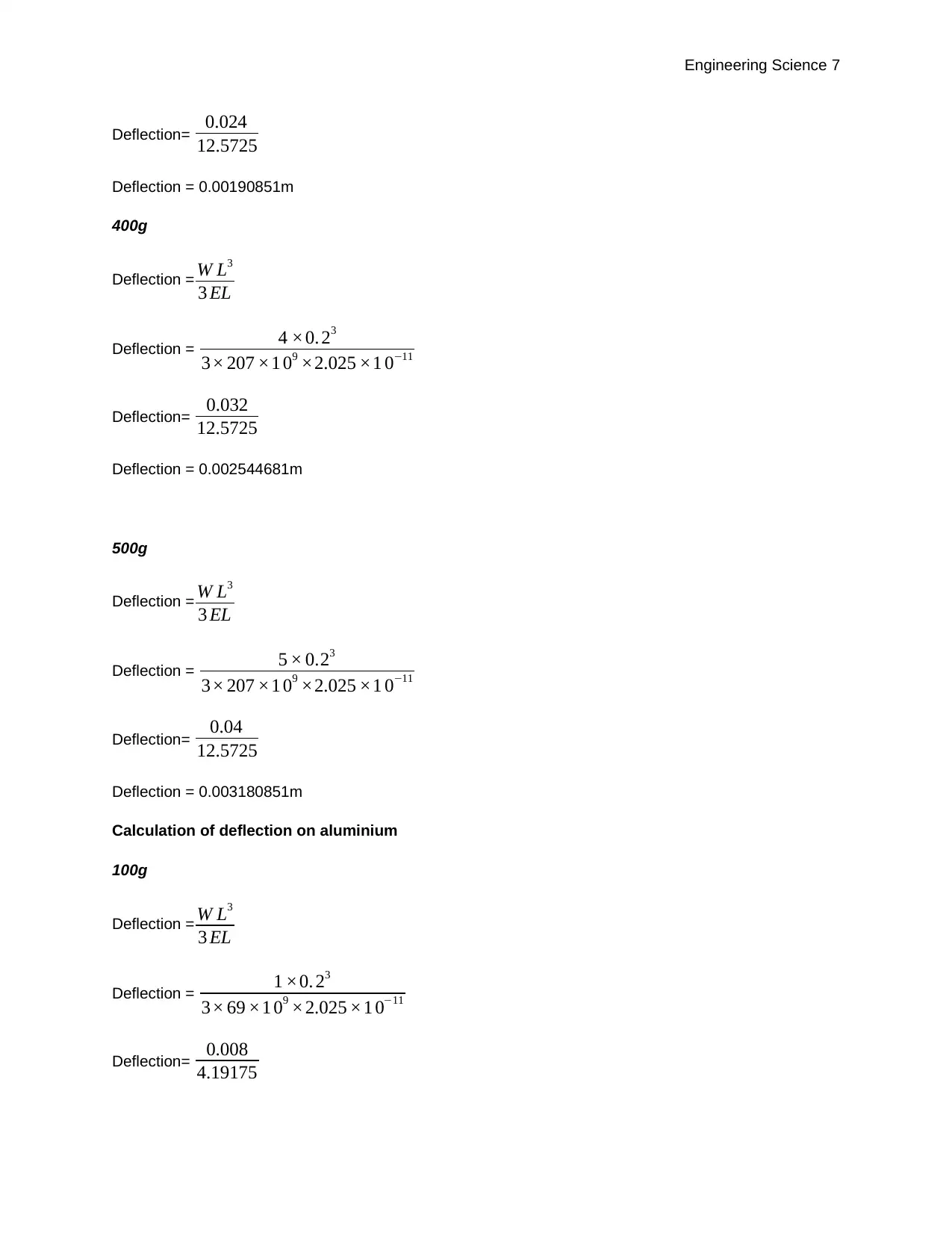
Deflection = 1 × 0.23
3× 207 ×1 09 ×2.025 ×1 0−11
Deflection= 0.008
12.5725
Deflection = 0.00063617m
200g
Deflection = W L3
3 EL
Deflection = 2 × 0.23
3× 207 ×1 09 ×2.025 ×1 0−11
Deflection= 0.016
12.5725
Deflection = 0.00127234m
300g
Deflection = W L3
3 EL
Deflection = 3 × 0.23
3× 207 ×1 09 ×2.025 ×1 0−11
⊘ This is a preview!⊘
Do you want full access?
Subscribe today to unlock all pages.

Trusted by 1+ million students worldwide
Engineering Science 7
Deflection= 0.024
12.5725
Deflection = 0.00190851m
400g
Deflection = W L3
3 EL
Deflection = 4 ×0. 23
3× 207 ×1 09 ×2.025 ×1 0−11
Deflection= 0.032
12.5725
Deflection = 0.002544681m
500g
Deflection = W L3
3 EL
Deflection = 5 × 0.23
3× 207 ×1 09 ×2.025 ×1 0−11
Deflection= 0.04
12.5725
Deflection = 0.003180851m
Calculation of deflection on aluminium
100g
Deflection = W L3
3 EL
Deflection = 1 ×0. 23
3× 69 ×1 09 ×2.025 ×1 0−11
Deflection= 0.008
4.19175
Paraphrase This Document
Need a fresh take? Get an instant paraphrase of this document with our AI Paraphraser
Engineering Science 8
Deflection = 0.00190851m
200g
Deflection = W L3
3 EL
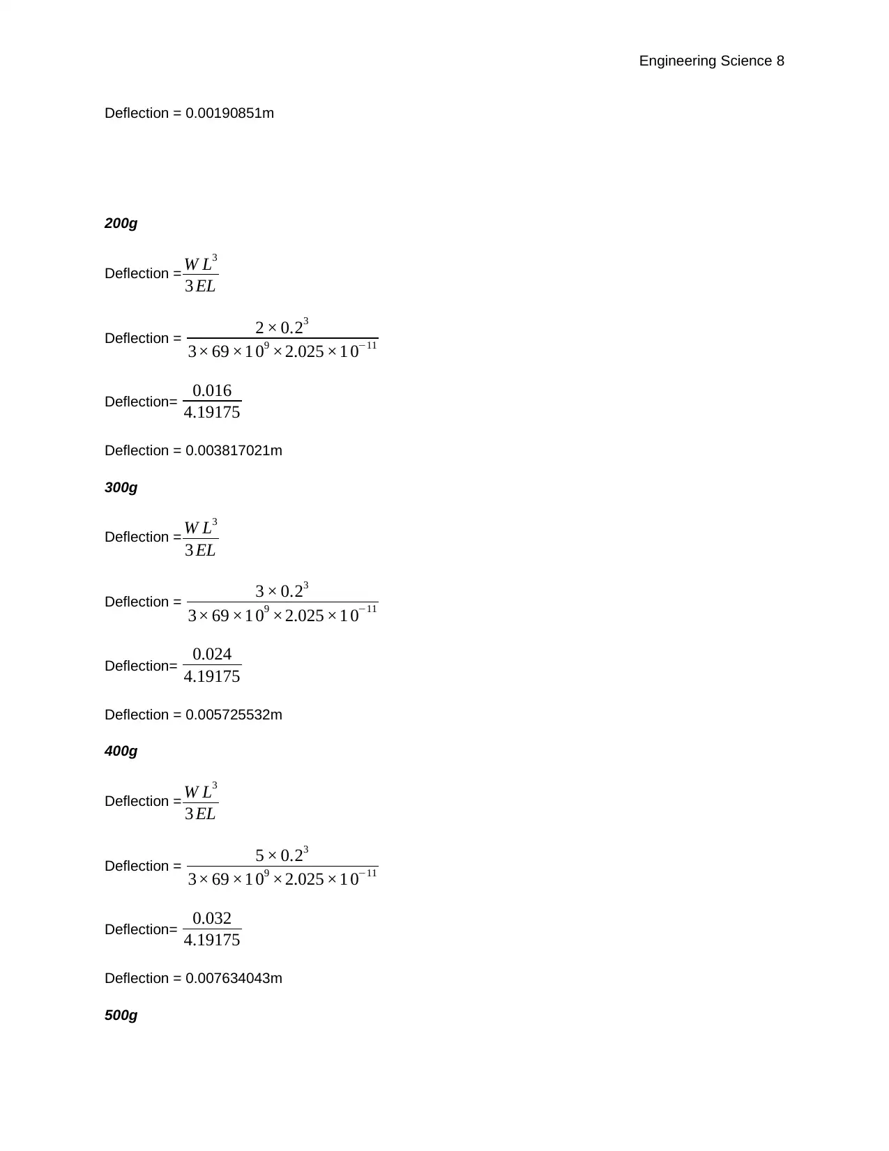
Deflection = 2 × 0.23
3× 69 ×1 09 ×2.025 ×1 0−11
Deflection= 0.016
4.19175
Deflection = 0.003817021m
300g
Deflection = W L3
3 EL
Deflection = 3 × 0.23
3× 69 ×1 09 ×2.025 ×1 0−11
Deflection= 0.024
4.19175
Deflection = 0.005725532m
400g
Deflection = W L3
3 EL
Deflection = 5 × 0.23
3× 69 ×1 09 ×2.025 ×1 0−11
Deflection= 0.032
4.19175
Deflection = 0.007634043m
500g
Engineering Science 9
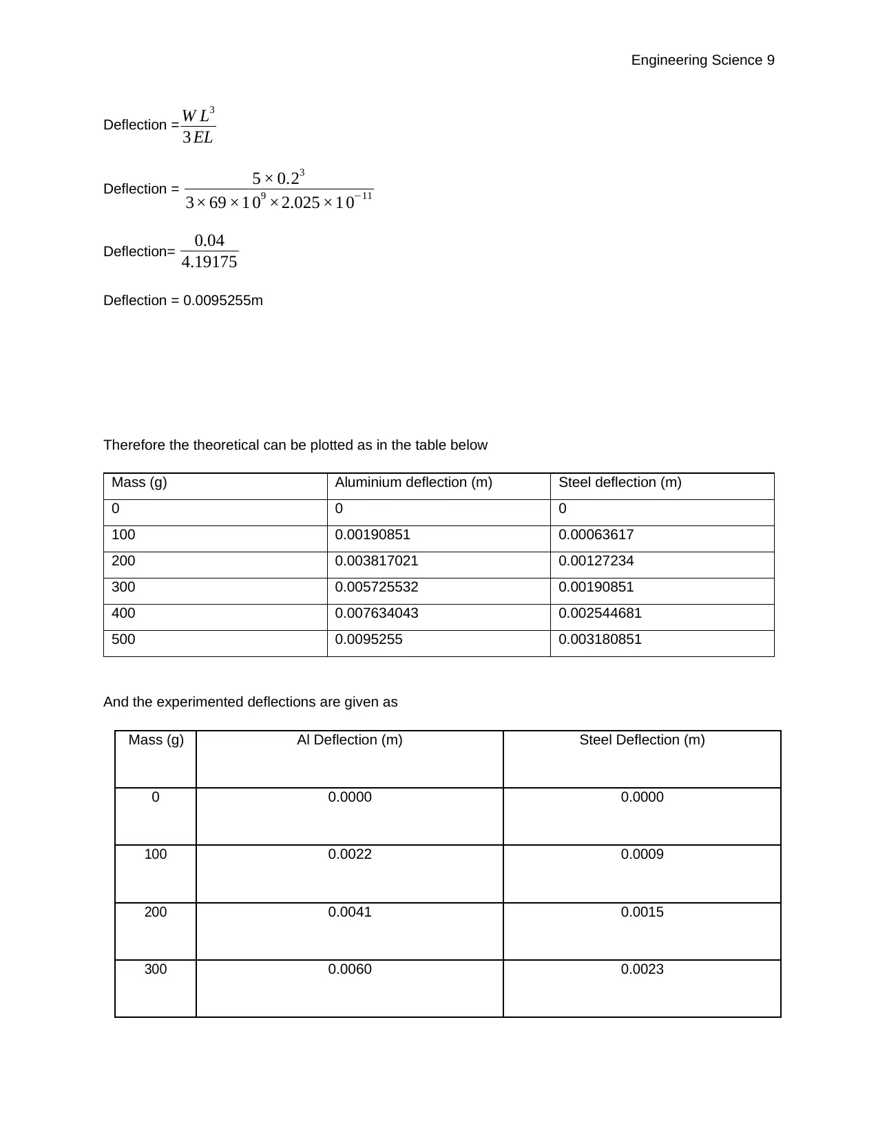
Deflection = W L3
3 EL
Deflection = 5 × 0.23
3× 69 ×1 09 ×2.025 ×1 0−11
Deflection= 0.04
4.19175
Deflection = 0.0095255m
Therefore the theoretical can be plotted as in the table below
Mass (g) Aluminium deflection (m) Steel deflection (m)
0 0 0
100 0.00190851 0.00063617
200 0.003817021 0.00127234
300 0.005725532 0.00190851
400 0.007634043 0.002544681
500 0.0095255 0.003180851
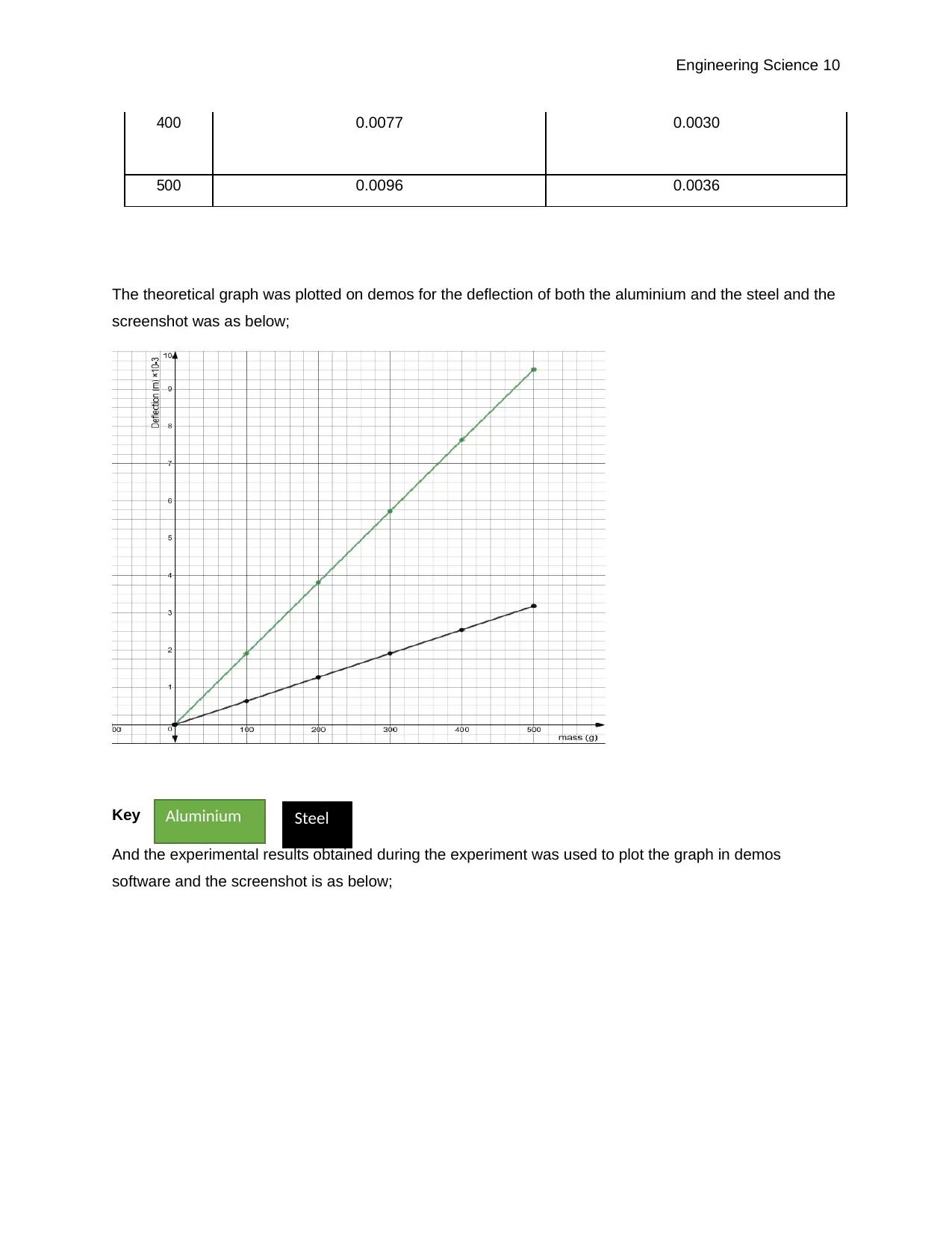
And the experimented deflections are given as
Mass (g) Al Deflection (m) Steel Deflection (m)
0 0.0000 0.0000
100 0.0022 0.0009
200 0.0041 0.0015
300 0.0060 0.0023
⊘ This is a preview!⊘
Do you want full access?
Subscribe today to unlock all pages.

Trusted by 1+ million students worldwide
Engineering Science 10
400 0.0077 0.0030
500 0.0096 0.0036
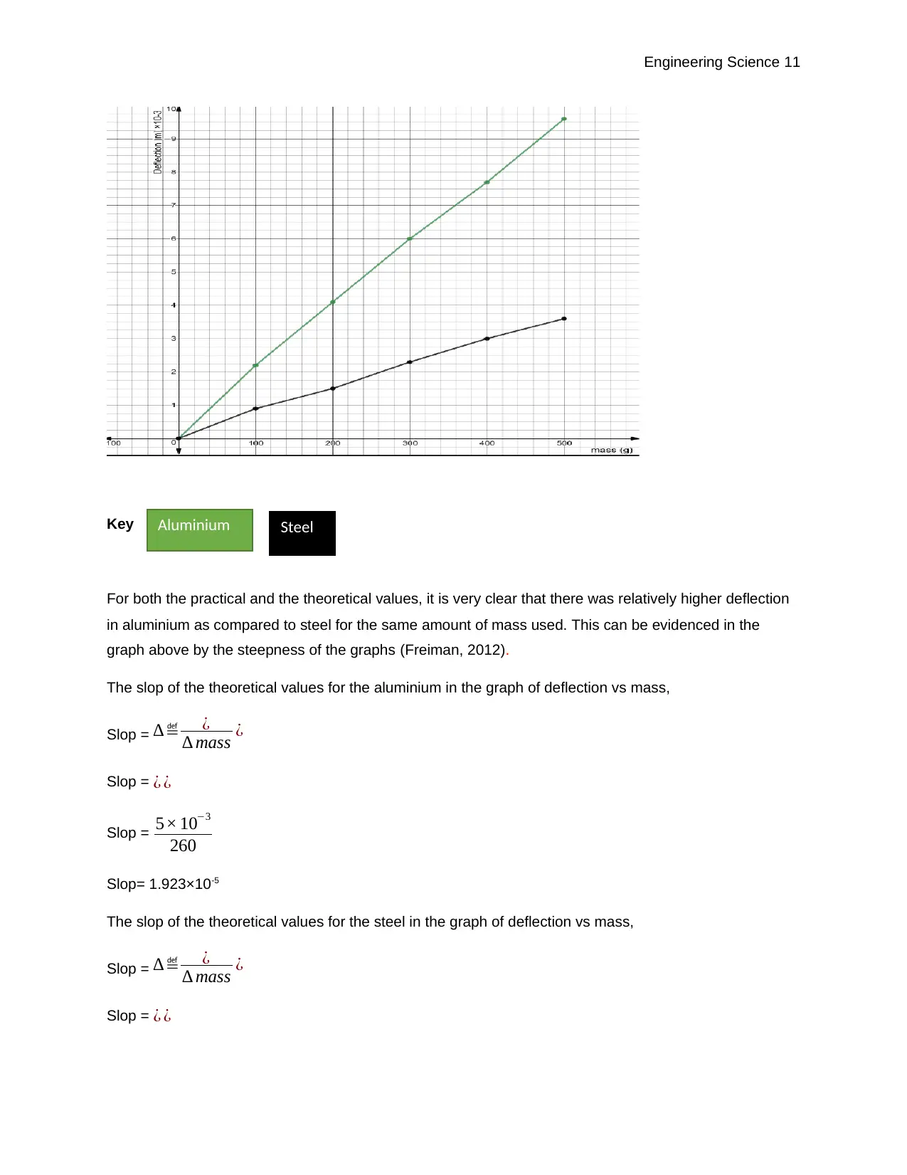
The theoretical graph was plotted on demos for the deflection of both the aluminium and the steel and the
screenshot was as below;
Key
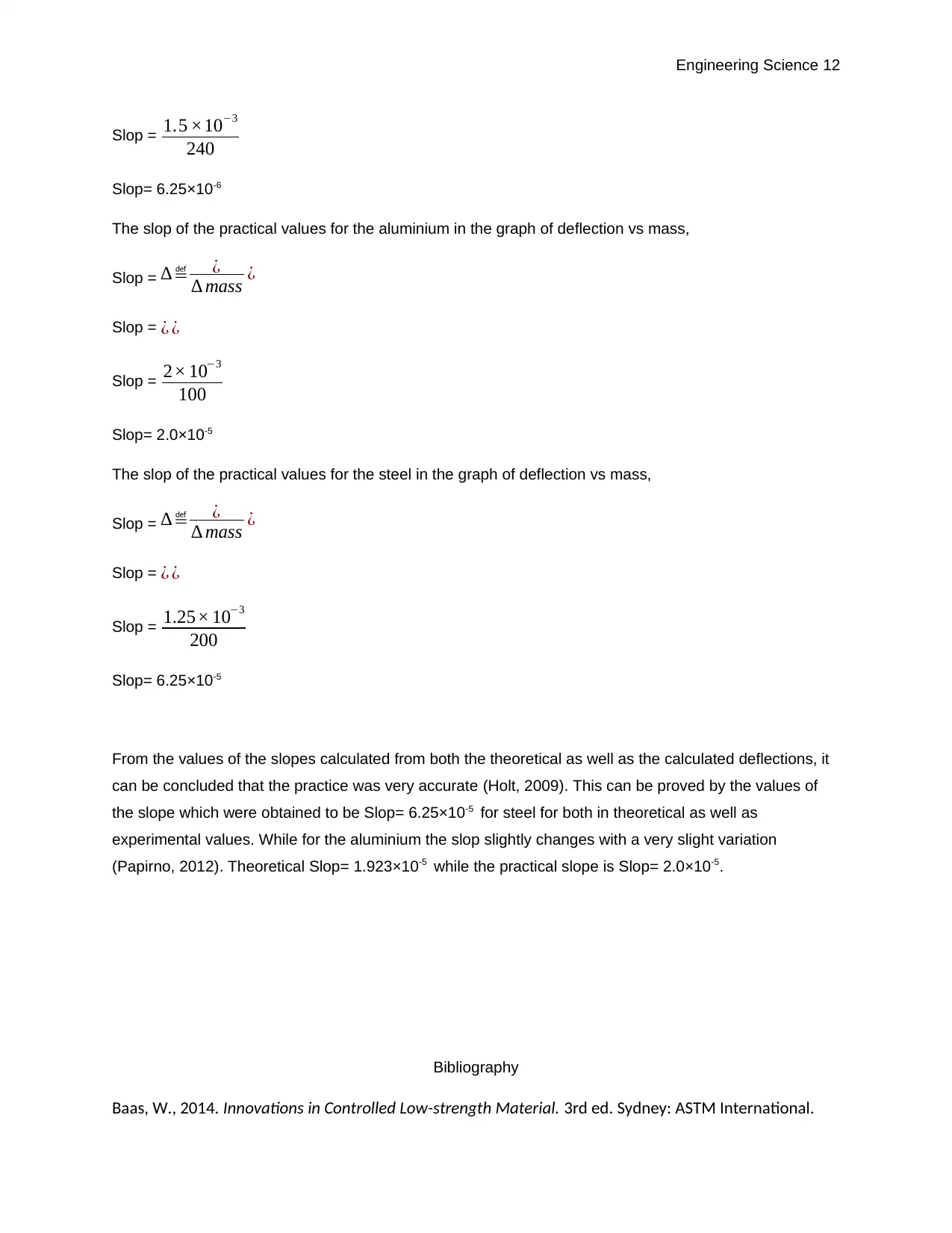
And the experimental results obtained during the experiment was used to plot the graph in demos
software and the screenshot is as below;
Aluminium Steel
Paraphrase This Document
Need a fresh take? Get an instant paraphrase of this document with our AI Paraphraser
Engineering Science 11
Key
For both the practical and the theoretical values, it is very clear that there was relatively higher deflection
in aluminium as compared to steel for the same amount of mass used. This can be evidenced in the
graph above by the steepness of the graphs (Freiman, 2012).
The slop of the theoretical values for the aluminium in the graph of deflection vs mass,
Slop = ∆≝ ¿
∆ mass ¿
Slop = ¿ ¿
Slop = 5× 10⁻³
260
Slop= 1.923×10⁻⁵
The slop of the theoretical values for the steel in the graph of deflection vs mass,
Slop = ∆≝ ¿
∆ mass ¿
Slop = ¿ ¿
Aluminium Steel
Engineering Science 12
Slop = 1.5 ×10⁻³
240
Slop= 6.25×10⁻⁶
The slop of the practical values for the aluminium in the graph of deflection vs mass,
Slop = ∆≝ ¿
∆ mass ¿
Slop = ¿ ¿
Slop = 2× 10⁻³
100
Slop= 2.0×10⁻⁵
The slop of the practical values for the steel in the graph of deflection vs mass,
Slop = ∆≝ ¿
∆ mass ¿
Slop = ¿ ¿
Slop = 1.25× 10⁻³
200
Slop= 6.25×10⁻⁵
From the values of the slopes calculated from both the theoretical as well as the calculated deflections, it
can be concluded that the practice was very accurate (Holt, 2009). This can be proved by the values of
the slope which were obtained to be Slop= 6.25×10⁻⁵ for steel for both in theoretical as well as
experimental values. While for the aluminium the slop slightly changes with a very slight variation
(Papirno, 2012). Theoretical Slop= 1.923×10⁻⁵ while the practical slope is Slop= 2.0×10⁻⁵.
Bibliography
Baas, W., 2014. Innovations in Controlled Low-strength Material. 3rd ed. Sydney: ASTM International.
⊘ This is a preview!⊘
Do you want full access?
Subscribe today to unlock all pages.

Trusted by 1+ million students worldwide
1 out of 13
Related Documents
Your All-in-One AI-Powered Toolkit for Academic Success.
+13062052269
info@desklib.com
Available 24*7 on WhatsApp / Email
![[object Object]](/_next/static/media/star-bottom.7253800d.svg)
Unlock your academic potential
Copyright © 2020–2026 A2Z Services. All Rights Reserved. Developed and managed by ZUCOL.


