Design of HVAC System for Act 1 and Act 2 Towers in Dubai
Added on 2023-04-23
29 Pages6847 Words479 Views
School of Engineering Undergraduate Programmes
2018-19
Individual Engineering Project (6E6Z1100_1819_9Z6)
Act 1 and Act 2 Towers
Student Name(s) ID Course
Mansour Madmouj 16044689 BENG (Hons) Mechanical Engineering
Abstract
The advancement in the field of science and technology has seen improvements in the
development of buildings thus enabling people live comfortable be it in commercial or
residential houses. The use of air conditioning has increased day to day hence
contributing to the emission of foreign gases into the atmosphere. Manufacturers of
different air conditioning machines have progressively improved in research towards
establishing environmentally friendly gases to be used as refrigerant. For instance, the
gases R32 and R147A are the latest environmentally gases to be used in the industry.
This lead to Building modelling of the Cooling loads in buildings and towers in more
efficient ways. To implement modern day technology can be very challenging because of
many factors, such as the climate, design requirements, the purpose of the building, and
so forth. The project under study here consisted of a high rise building which would be
used for residential purposes. The mechanical design layout was provided by the
consultant. Engineers implementing the project as contractors are then tasked to verify all
the design criteria and come up with shop drawings that meet the project requirement and
addresses all the site conditions. Thereafter, the contractors are expected to execute the
project as outlined in the project specifications, design drawings and project documents
issued by the consultant team. For the HVAC system, intelligent humans have innovate
modern and better technology to help in cooling the houses while saving our surrounding
environment. At the same time, correct sizing of the ac machines help in saving energy
(Sustainable future | Carrier air conditioning, 2018). Also, the sizing can be aided by the
software Hourly Analysis Program (HAP) which is efficient in designing the HVAC
system for a building site in that it consider sufficient critical information. The project
displays an ongoing real-life project in Dubai. In addition, Due to Dubai’s hot climate,
this is a challenging factor to overcome. The design will also be executed by using
Autocad 2D, and Autocad Revit to give an idea of the 3-dimensional analysis and 2-
dimensional analysis of the ductwork throughout the 6th typical floor.
Individual Engineering Project (6E6Z1100_1819_9Z6)
Contents
Abstract.................................................................................................................................................1
Introduction...........................................................................................................................................2
Literature Survey...................................................................................................................................3
Method..................................................................................................................................................4
Hourly Analysis Program (HAP)......................................................................................................6
Results.................................................................................................................................................11
Manual Calculations....................................................................................................................11
Hourly Analysis Program (HAP):........................................................................................................20
Discussion...........................................................................................................................................22
Conclusion..........................................................................................................................................25
Bibliography......................................................................................................................................27
Page 1
Individual Engineering Project (6E6Z1100_1819_9Z6)
Introduction
As the summer heat in GCC can push the temperature to reach the 40s, the HVAC system is
not so much a luxury but a necessity in the building systems. The importance of such major
energy-consuming element has pushed researchers, scientists & field experts to incorporate
huge development regarding system components, mechanism, & even building architecture.
A typical centralised HVAC system consists of two major sections. The first section is the in-
building and the second is the outer section of the building. Furthermore, the system can be
broken down into five loops; indoor air loops, refrigerant loops, chilled water loops, free air
loops and condensate water loops. These loops are the building block of a comfortable
atmosphere within a building. These integral parts of the in-building loops have primary
components; terminal units, cooling coils, dampers, fans, ducts, and system controls. Also,
the chilled water loop consists of cooling coils, chiller evaporators, pumps, pipes, valves, and
system controls (2006 ASHRAE handbook, 2006). The most challenging segment in
designing a compatible HVAC system is the energy consumption as the in-door section
consists of the substantial amount of parts. This significant portion leads to high energy
consumption. Therefore, building energy-efficient system is the major part of Engineers’
mission. In this project, a comprehensive study of the design of a high rise building located in
the United Arab Emirates. The summers are hot and humid with day temperature at 42°C and
29.7 °C at night. Most days are sunny and clear, and winters are short and slightly warm.
During winter, day temperature is 23 °C and lows of 14 °C at night.
Moreover, the precipitation level has increased over the past decade with accumulated rain
intensity reaching 87.3 mm per year. In addition to the extremely hot weather, it is also
known of high humidity level that peaks to 65 (Mediaoffice.ae, 2018). Building a luxurious
tower in one of the most expensive communities in UAE; Downtown Dubai’s District at
Emaar Boulevard is an actual challenge. The tower is located near to the tallest skyscraper in
the World; Burj Khalifa. It is elegantly designed with 71 residential floors. The tower
includes four basements, Ground floor, Podium, six townhouses, amenity floor, 52 storeys
residential floors, two penthouses and seven technical floors. The total project area is 6700
m2 with a total built-up area of 93,000 m2. The residential area is almost 55,000 m2. However,
the tower also consists of mechanical floors that contain the in-door HVAC system.
Basement 3, third floor, eighteenth/Nineteenth floor, the forty-three/ forty-four floor, and the
sixty-eighth floor.
The cooling system applied will be provided through a central cooling plant which is a
governmental district cooling plant. Preceding a successful work in designing an HVAC
system, multiple factors are considered. Weather and Climate change is a core structure that
engineers reflect on. Heat gain in a building can happen because of solar energy coming
through the windows, or it could be due to internal devices, for example, lightning, electrical
equipment’s and people’s body heat (Sauer, Howell and Coad 2010 p. 45). The tower will
undergo a complex system of Air conditioning that will be chilled water that passes through
cooling coils in heat exchangers. The HVAC chilled water system works by supplying water
to a primary heat exchanger that is installed on the side of the water pumps. For example, five
Page 2
Individual Engineering Project (6E6Z1100_1819_9Z6)
heat exchangers plate type would be working on duty to exchange the cooling energy to the
building side, the temperature difference on the secondary side will be 16°C, and the third
stage is two heat exchangers based on the mechanical floor at Level 43 and 44 to serve the
typical tower floors from Level 45 until Level 70, the temperature difference will be 16°C on
the primary side (5.5°C to 14.4°C). The cold water runs into the fan coil units. In return, the
hot water that will be recirculated can be used by another utility for heating purposes (Rezaie
and Rosen 2012 p. 36]. The energy consumption of the complex system is usually high
because it serves multiple zones in each area, and due to the extremely hot weather much
more cooling load is required to reach a comfortable atmosphere. One of the main design
factors that will be focused on is the size of the equipment. Therefore, for a large multiple-
zone VAV system the fan energy use will be gigantically high if an undersized fan is
equipped. Ventilation is also part of the design; it is broken down into two paths. The first
path is the mechanical ventilation that uses fans to recirculate air inside the building to the
outside. The requirements of minimum air ventilation are in ASHRAE Standard 62.1 [2006
ASHRAE handbook, 2006]. The second part of ventilation is the natural type that does not
need any equipment. However, it is done by specifically designing airflow ventilation paths
using a pressurised air system. In other words, it is called the air changes per hour (ACPH).
Equation (X)
Where:
ACPH - number of air changes/hour.
Vol - volume of the space l ×w × h in meters cubic.
Q - volumetric flow rate in cubic meters/minute.
Air distribution arrangements in each area aim to reach a pressure equilibrium. The capacity
of air leaving and entering the space must be the equal (Bearg 2013 p. 23). Moreover, air
change rates are dependent on the design of the commercial building, for example, residential
area ventilation rates are calculated based on the parameters of the architectural plan and the
number of the occupants. On the other hand, non-occupational areas like parking basement
standards require larger amounts of air change rates because of air contaminant due to
exhaust gases [2006 ASHRAE handbook, 2006]. Also, the heat energy recovery ventilation is
utilised by using the latent heat absorption from the exhaust gasses. This supports energy
efficiency in Ventilation energy recovery.
Literature Survey
The process of providing a comfortable environment for occupants in a given space,
commercial or domestic, is done by Air conditioning. Air conditioning is needed because it is
resposible for the removable of moist and heat from an occupied space. This process can also
be used to cool and humidfy regions that contain equipment that produce a lot of heat due to
Page 3
Individual Engineering Project (6E6Z1100_1819_9Z6)
its functionality. For example, Main frame computers that work non-stop in large
coorperations need air conditioners to make sure that they run smoothly without over heating.
The heat transfer principles are used to describe how air conditioning and heating systems
can maintain the comfortable environment for the people. The Split Unit airconditioning
found in households can be used as an example of this process of transferring heat, the
process starts when the air conditioner collect’s hot air from the given space. This hot air is
processed within the system of the Air conditioner. When the hot air pass through a chemical
called the refrigerant along with a bunch of coils, cold air is produced. When one person
switches on the A/C system to a desired temperature, the thermostat in the system starts to
sense the temperature of the environment of the room (Spitler and Fisher 2009 p. 81). The
Cooling device is equiped with certain areas that draws in the hot air and pass it through a
grille that, then it flows within a chain of pipes that contain the refrigant. However, there are
some outcomes due to this process. The first outcome is that the refrigerant used gets hot and
is no longer capable of cooling the air, although it is sustainable. The refrigerant liquid will
absorb the heat and transfers into a hot gas. The second outcome is that the moisture inside
the air is also absorbed by the evaporating coils. The process is sustainable so, the hot gas
will pass onto the compressor to increase its temperature (Rees, Spitler, Davies, and Haves
2010 p. 71). When temperature increase, as a result the pressure will also increase. The high
pressurised hot liquid travels through to the condenser, and the state will quickly change into
a cooler liquid because the hot gas will dissipate heat to the surrounding throughout the metal
fins . The refrigerant leaves the condenser with low temperature through an expansion valve.
This device controls the flow of cool liquid refrigerant and redirects back to the indoor unit
where hot air from the room is cooled. This process repeated by the Air Conditioners until a
certain atmosphere is met by the occupiants.
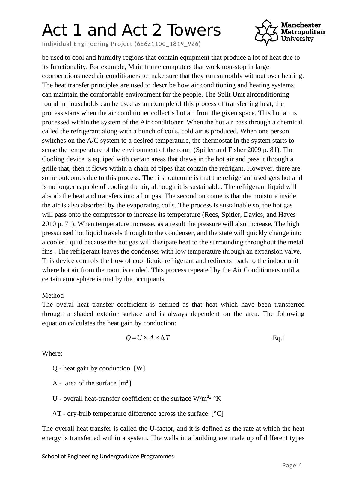
Method
The overal heat transfer coefficient is defined as that heat which have been transferred
through a shaded exterior surface and is always dependent on the area. The following
equation calculates the heat gain by conduction:
Q=U × A ×∆ T Eq.1
Where:
Q - heat gain by conduction [W]
A - area of the surface [m2 ]
U - overall heat-transfer coefficient of the surface W/m2• °K
∆T - dry-bulb temperature difference across the surface [°C]
The overall heat transfer is called the U-factor, and it is defined as the rate at which the heat
energy is transferred within a system. The walls in a building are made up of different types
of layers, and each layer has a unique U-Factor. The U-factors are calculated for a given wall
by adding the inverse value of the thermal resistance of each material (R-Values). The
Page 4
its functionality. For example, Main frame computers that work non-stop in large
coorperations need air conditioners to make sure that they run smoothly without over heating.
The heat transfer principles are used to describe how air conditioning and heating systems
can maintain the comfortable environment for the people. The Split Unit airconditioning
found in households can be used as an example of this process of transferring heat, the
process starts when the air conditioner collect’s hot air from the given space. This hot air is
processed within the system of the Air conditioner. When the hot air pass through a chemical
called the refrigerant along with a bunch of coils, cold air is produced. When one person
switches on the A/C system to a desired temperature, the thermostat in the system starts to
sense the temperature of the environment of the room (Spitler and Fisher 2009 p. 81). The
Cooling device is equiped with certain areas that draws in the hot air and pass it through a
grille that, then it flows within a chain of pipes that contain the refrigant. However, there are
some outcomes due to this process. The first outcome is that the refrigerant used gets hot and
is no longer capable of cooling the air, although it is sustainable. The refrigerant liquid will
absorb the heat and transfers into a hot gas. The second outcome is that the moisture inside
the air is also absorbed by the evaporating coils. The process is sustainable so, the hot gas
will pass onto the compressor to increase its temperature (Rees, Spitler, Davies, and Haves
2010 p. 71). When temperature increase, as a result the pressure will also increase. The high
pressurised hot liquid travels through to the condenser, and the state will quickly change into
a cooler liquid because the hot gas will dissipate heat to the surrounding throughout the metal
fins . The refrigerant leaves the condenser with low temperature through an expansion valve.
This device controls the flow of cool liquid refrigerant and redirects back to the indoor unit
where hot air from the room is cooled. This process repeated by the Air Conditioners until a
certain atmosphere is met by the occupiants.
Method
The overal heat transfer coefficient is defined as that heat which have been transferred
through a shaded exterior surface and is always dependent on the area. The following
equation calculates the heat gain by conduction:
Q=U × A ×∆ T Eq.1
Where:
Q - heat gain by conduction [W]
A - area of the surface [m2 ]
U - overall heat-transfer coefficient of the surface W/m2• °K
∆T - dry-bulb temperature difference across the surface [°C]
The overall heat transfer is called the U-factor, and it is defined as the rate at which the heat
energy is transferred within a system. The walls in a building are made up of different types
of layers, and each layer has a unique U-Factor. The U-factors are calculated for a given wall
by adding the inverse value of the thermal resistance of each material (R-Values). The
Page 4
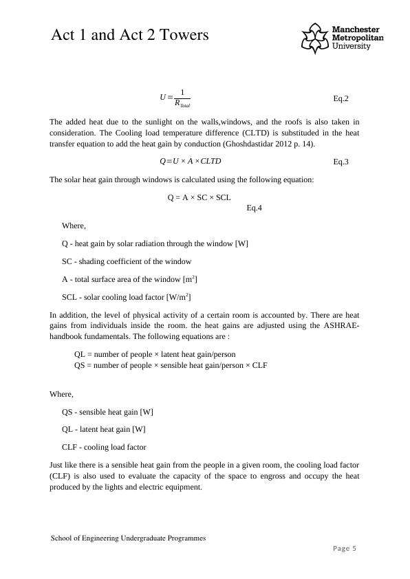
Individual Engineering Project (6E6Z1100_1819_9Z6)
ASHRAE handbook arranges all of the thermal resistances of many materials used in
construction.
U = 1
RTotal
Eq.2
The added heat due to the sunlight on the walls,windows, and the roofs is also taken in
consideration. The Cooling load temperature difference (CLTD) is substituded in the heat
transfer equation to add the heat gain by conduction (Ghoshdastidar 2012 p. 14).
Q=U × A ×CLTD Eq.3
The solar heat gain through windows is calculated using the following equation:
Q = A × SC × SCL
Eq.4
Where,
Q - heat gain by solar radiation through the window [W]
SC - shading coefficient of the window
A - total surface area of the window [m2]
SCL - solar cooling load factor [W/m2]
In addition, the level of physical activity of a certain room is accounted by. There are heat
gains from individuals inside the room. the heat gains are adjusted using the ASHRAE-
handbook fundamentals. The following equations are :
QL = number of people × latent heat gain/person
QS = number of people × sensible heat gain/person × CLF
Where,
QS - sensible heat gain [W]
QL - latent heat gain [W]
CLF - cooling load factor
Just like there is a sensible heat gain from the people in a given room, the cooling load factor
(CLF) is also used to evaluate the capacity of the space to engross and occupy the heat
produced by the lights and electric equipment.
Page 5
End of preview
Want to access all the pages? Upload your documents or become a member.