Engineering Visualization: 3D Object Design, Rotation, and Texture
VerifiedAdded on 2023/06/11
|12
|2149
|289
Practical Assignment
AI Summary
This assignment focuses on engineering visualization, detailing the design, rotation, and visualization of 3D objects using OpenGL. It covers key concepts such as 3D object creation using edges, faces, and vertices, object rotation using Euler's rotation rule, and the z-buffer algorithm for hidden surface removal. The project also explores texture mapping for adding surface details and redesigning 3D projects using Bezier surface patches. The steps involved in each process are explained, including the initialization of parameters, application of functions, and the generation of results based on user input. The assignment concludes with a summary of how texture mapping can be achieved from the original object using orthogonal projection, Bezier curve patches, and texture mapping techniques. Desklib provides a platform to access this and similar solved assignments.

2018
Engineering Visualization
Engineering Visualization
Paraphrase This Document
Need a fresh take? Get an instant paraphrase of this document with our AI Paraphraser
Table of Contents
1. Design 3D Object:..................................................................................................................................3
2. Rotate the object:...................................................................................................................................4
3. Visualizing project:...............................................................................................................................6
4. Adding requirements:...........................................................................................................................7
5. Redesign the 3D project:.......................................................................................................................9
6. Task Performance:..............................................................................................................................11
References................................................................................................................................................12
1
1. Design 3D Object:
It is also known as the three dimensional object which related to perform the
mathematical description of the object. It has three components such as Edges, Faces and
Vertices. It is mainly used for creating and manipulating the data. It can be expressed as a
convex polyhedrons also known as Euler’s formula that might be combined together.
Generally, three dimension extension comes from the two dimension model and
added to an arbitrary axis. Most of the properties are similar to two dimension model.
Orthographic projection is providing the quality of the object and its mainly used
for service engineer field. It has six arguments such as up, bottom, left, right, far and near .This
parameters are created by this model functionally.
This can be summarized by the OpenGL library interfaces for providing the
Application Programming Interfaces to form a two dimension and three dimension of an object.
These function can be associated by the three factors could be following as texture mapping,
rendering of the surface and the final one is illumination. This operation is mainly focused upon
the formulation of each patch. In these scenario, we have to use the passing parameters and
functions to call upon from the starting position of the part as the main() function. This can be
enlarged with the result to show up whether it presses the key value as one on the keyboard.
The steps are explained by using the OpenGL import files as this project. These
steps are involving below as,
The starting stage of this project is main() function to providing the parameters and
functions into outside function.
The OpenGL library files can be involved as the three aspect of the functions as follow
as,
2
⊘ This is a preview!⊘
Do you want full access?
Subscribe today to unlock all pages.
Trusted by 1+ million students worldwide
First one is initGL function act as initialization factors of these parameters,
Second one is a reshape function act as changing the shape of the object,
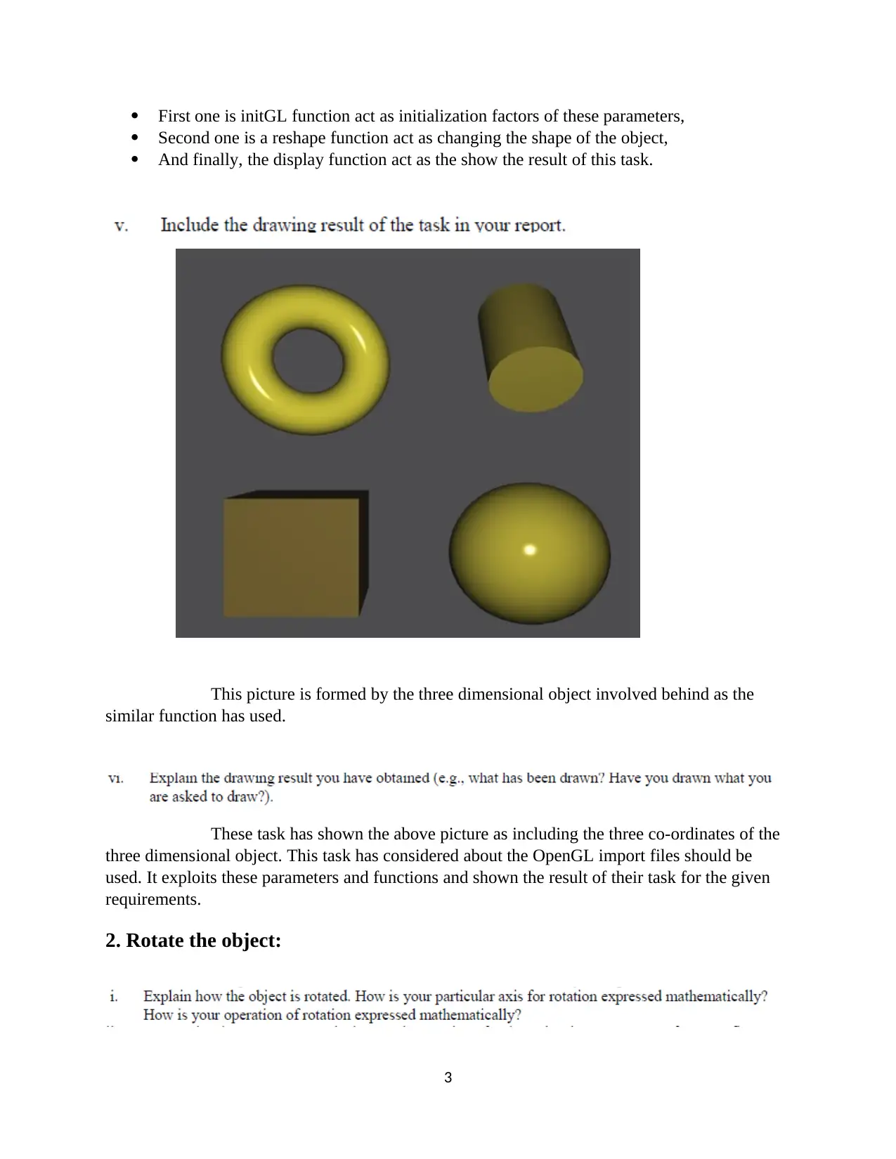
And finally, the display function act as the show the result of this task.
This picture is formed by the three dimensional object involved behind as the
similar function has used.
These task has shown the above picture as including the three co-ordinates of the
three dimensional object. This task has considered about the OpenGL import files should be
used. It exploits these parameters and functions and shown the result of their task for the given
requirements.
2. Rotate the object:
3
Second one is a reshape function act as changing the shape of the object,
And finally, the display function act as the show the result of this task.
This picture is formed by the three dimensional object involved behind as the
similar function has used.
These task has shown the above picture as including the three co-ordinates of the
three dimensional object. This task has considered about the OpenGL import files should be
used. It exploits these parameters and functions and shown the result of their task for the given
requirements.
2. Rotate the object:
3
Paraphrase This Document
Need a fresh take? Get an instant paraphrase of this document with our AI Paraphraser
It can be exchanged co-ordinate positions between them. It can also be altering
signs. It can be specified as the Orthogonal projection of the rotation matrix. It might be
formulated as the Euler’s rotation rule as well as the right-hand rule.
The two dimension altering sign is easy way to determine. In these, the three
dimension rotation is equivalent process to the two dimension rotation in which altering co-
ordinate with the arbitrary point. This can be formulated by three constraints as following the
rotation, transformation and inverse of the rotation.
These can be summarized by the following categories such as changing the
rotation of the object from the origin, moving the object for the given angle, performing the
rotation task for the given angle, move to the inverse operation of the given rotation angle comes
up the original object, and finally changing the rotation axis to the origin.
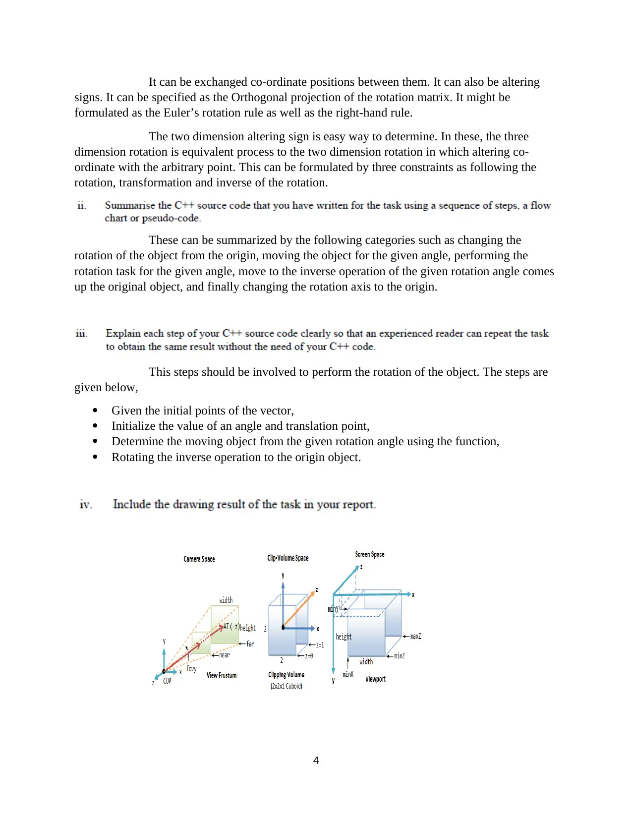
This steps should be involved to perform the rotation of the object. The steps are
given below,
Given the initial points of the vector,
Initialize the value of an angle and translation point,
Determine the moving object from the given rotation angle using the function,
Rotating the inverse operation to the origin object.
4
signs. It can be specified as the Orthogonal projection of the rotation matrix. It might be
formulated as the Euler’s rotation rule as well as the right-hand rule.
The two dimension altering sign is easy way to determine. In these, the three
dimension rotation is equivalent process to the two dimension rotation in which altering co-
ordinate with the arbitrary point. This can be formulated by three constraints as following the
rotation, transformation and inverse of the rotation.
These can be summarized by the following categories such as changing the
rotation of the object from the origin, moving the object for the given angle, performing the
rotation task for the given angle, move to the inverse operation of the given rotation angle comes
up the original object, and finally changing the rotation axis to the origin.
This steps should be involved to perform the rotation of the object. The steps are
given below,
Given the initial points of the vector,
Initialize the value of an angle and translation point,
Determine the moving object from the given rotation angle using the function,
Rotating the inverse operation to the origin object.
4
This picture can be formed behind the rotation of the given angle from the user
and performing the rotation of the inverse operation to show up in the origin object when the key
value press as two.
These scenario can mainly focused on the rotation of the object from the origin.
This can be configured as the SetupRotation() function can be used. In these function can be
determined by the moving operation of the given angle from the user.
3. Visualizing project:
The z-buffer algorithm is a technique created by Cutmull and its widely used as a
hidden surface problem. It is also known as Depth-buffer algorithm. This concept is mainly
focuses on unclear image of the viewer. These object is varied from the clear images as well as
the original image. The following algorithm can be expressed as,
Initialize the values of the depthbuffer and framebuffer that is depthbuffer as zero
and framebuffer is assigned some background color.
Once a polygon is processed by one at a time
Depth value can be calculated depending upon the incrementation by the co-
ordinates polygons of each position
If the depth value is greater than the depthbuffer of the co-ordinates, it computes
the surface color and exchanging the values of the depthbuffer and framebuffer
Projection can be customized by two way of projection as well as the orthogonal
and perspective. This part can be configured by the orthogonal projection in these focused upon
the one point as well as the polygons at a time.
The steps are involving the parameters configuration of the projection of object at
one point. The steps are,
5
⊘ This is a preview!⊘
Do you want full access?
Subscribe today to unlock all pages.
Trusted by 1+ million students worldwide
Initialize the parameters as height and width for pixel coordinates and color value of
pixel,
Determine the depth value as performing the projection,
If the width is greater than and equal to height, the polygon can be setup,
Using these parameters, performing the polygons of the object at one point.
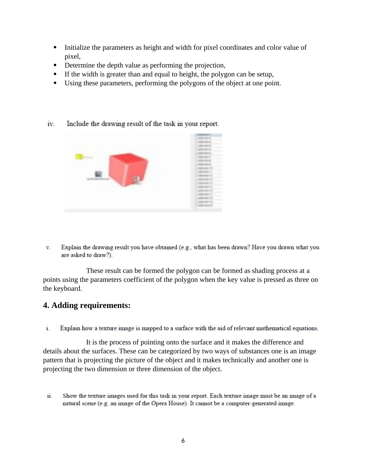
These result can be formed the polygon can be formed as shading process at a
points using the parameters coefficient of the polygon when the key value is pressed as three on
the keyboard.
4. Adding requirements:
It is the process of pointing onto the surface and it makes the difference and
details about the surfaces. These can be categorized by two ways of substances one is an image
pattern that is projecting the picture of the object and it makes technically and another one is
projecting the two dimension or three dimension of the object.
6
pixel,
Determine the depth value as performing the projection,
If the width is greater than and equal to height, the polygon can be setup,
Using these parameters, performing the polygons of the object at one point.
These result can be formed the polygon can be formed as shading process at a
points using the parameters coefficient of the polygon when the key value is pressed as three on
the keyboard.
4. Adding requirements:
It is the process of pointing onto the surface and it makes the difference and
details about the surfaces. These can be categorized by two ways of substances one is an image
pattern that is projecting the picture of the object and it makes technically and another one is
projecting the two dimension or three dimension of the object.
6
Paraphrase This Document
Need a fresh take? Get an instant paraphrase of this document with our AI Paraphraser
This process is a part of a shading process. This pattern is considered by the
process of focusing point to the surfaces to performing parameters. Then the result has shown as
when the key as generated as four.
It acts like as a input as vectors and pixels can be generalized to the geometric
operation and pixel operation and then performing the texture mapping. Instead of, we
considered the shading point of the coordinates. Finally, the result has shown as display function.
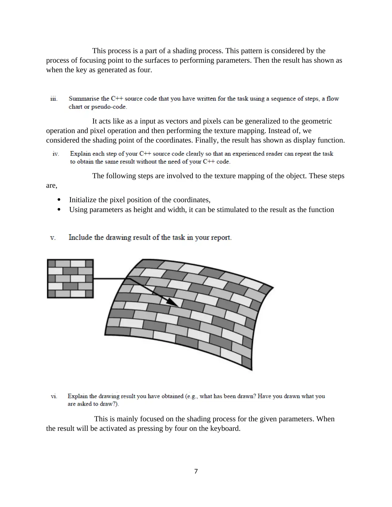
The following steps are involved to the texture mapping of the object. These steps
are,
Initialize the pixel position of the coordinates,
Using parameters as height and width, it can be stimulated to the result as the function
This is mainly focused on the shading process for the given parameters. When
the result will be activated as pressing by four on the keyboard.
7
process of focusing point to the surfaces to performing parameters. Then the result has shown as
when the key as generated as four.
It acts like as a input as vectors and pixels can be generalized to the geometric
operation and pixel operation and then performing the texture mapping. Instead of, we
considered the shading point of the coordinates. Finally, the result has shown as display function.
The following steps are involved to the texture mapping of the object. These steps
are,
Initialize the pixel position of the coordinates,
Using parameters as height and width, it can be stimulated to the result as the function
This is mainly focused on the shading process for the given parameters. When
the result will be activated as pressing by four on the keyboard.
7
5. Redesign the 3D project:
This topic is introduced by the two ways as parametric curve and parametric
surface patches. This can be mainly focused on Bezier surface patches and it is considered for
the two dimension and three dimension objects. This concept depends upon the control points.
According to the control points, two dimension has four control points and three dimensions has
sixteen control points.
These control points are categorized by three ways such as shaded polygons,
generated patch and wireframe.
It can be used to observe the object. Even though it is used for shadow in arts,
light sources and the handwriting texts. These can be provided by lighting model as well as the
shading model. It is used to determine whether the light intensity of the view on the surface with
an object.
These effects are considered with this models and contributed behinds the
interaction between the objects on the surfaces in which emits the light sources. These
parameters can be formulated by three ways of attributes such as the first one is a surface
parameters as providing the reflection of the light from the plane or surface, second one is eye as
well as camera such as providing the sensor quality of the object, and the third one is light source
of an object which provide electro spectrum of an object.
These can be focused upon the forming of the polygons in which could be
generalized between polygons. These model might be characterized by two ways of the
rendering such as calculating the average number of polygons within the surfaces and it can be
specified in polygons in each vertex (Dai, Feng & Hough, 2014) .
8
⊘ This is a preview!⊘
Do you want full access?
Subscribe today to unlock all pages.
Trusted by 1+ million students worldwide
These conversion is related to the Bezier surface patch from the texture mapping
with the object. This conversion is formulated by the following categories such as this patches
are rendered from the object to the polygon mesh, this control points can be formed by the
polygon mesh, this mechanism can be rendered by some algorithm to be used like subdivision
algorithm, these patches can be used to break up the different depths and thus depths are
subdivided into some patches, finally our answer is came in which can be rendered from the
texture mapping to Bezier surface patches.
This process is a part of unclear image of the object. This pattern is considered by
the process of focusing point to the surfaces to performing parameters (Wang, 2014) . Then the
result has shown as when the key value as generated by five.
This part can be generated by the changing the pixel position of the object
whether the object can be formed by Bezier curve patches to be applied.
The steps are involved as the following sentences,
Using the parameters as height, weight and pixel value might be initialized,
Using the patches of Bezier curve can be formed as pixel position might be changing as
the function of glBegin(),
When the result as stored to press as five on the keyboard.
9
Paraphrase This Document
Need a fresh take? Get an instant paraphrase of this document with our AI Paraphraser
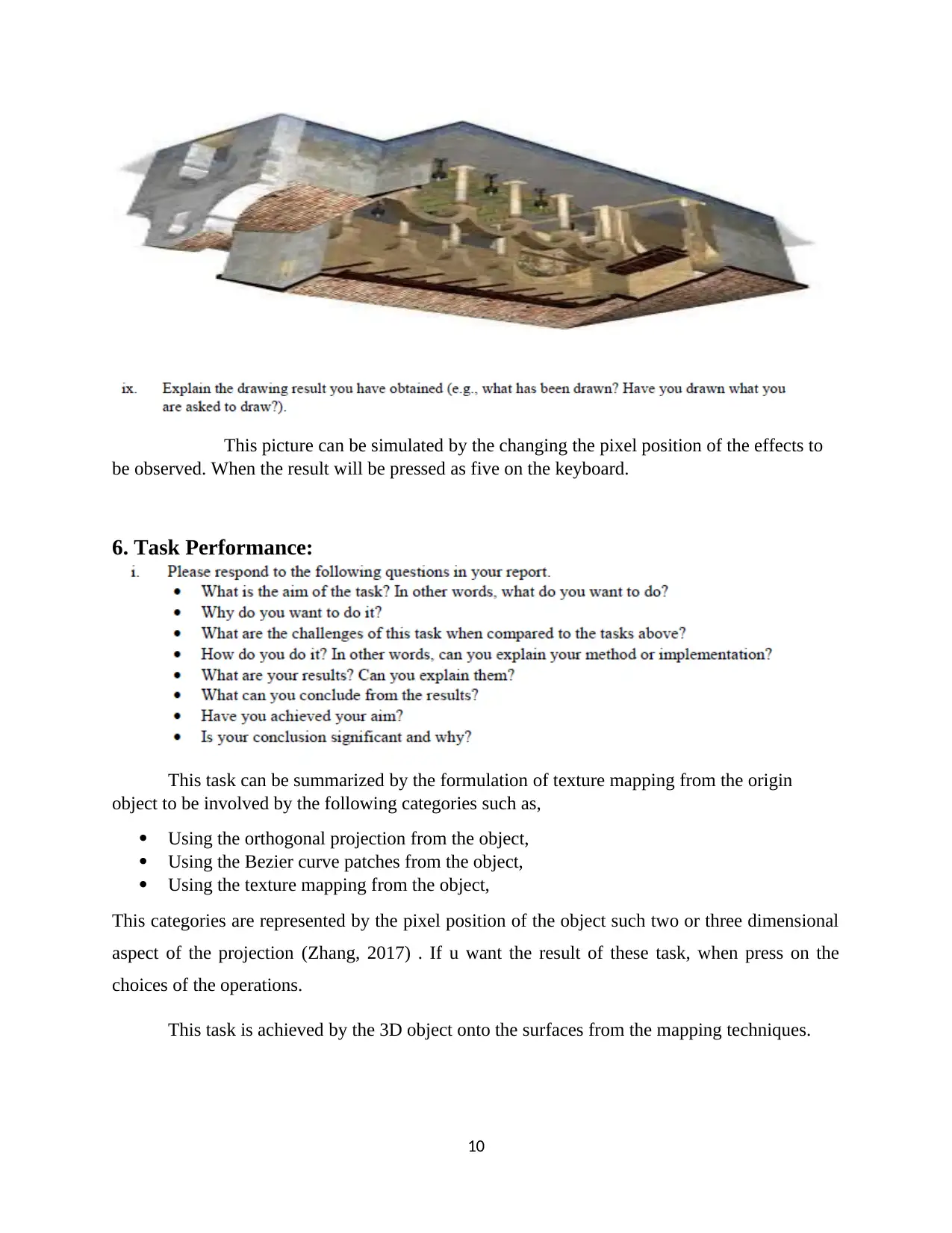
This picture can be simulated by the changing the pixel position of the effects to
be observed. When the result will be pressed as five on the keyboard.
6. Task Performance:
This task can be summarized by the formulation of texture mapping from the origin
object to be involved by the following categories such as,
Using the orthogonal projection from the object,
Using the Bezier curve patches from the object,
Using the texture mapping from the object,
This categories are represented by the pixel position of the object such two or three dimensional
aspect of the projection (Zhang, 2017) . If u want the result of these task, when press on the
choices of the operations.
This task is achieved by the 3D object onto the surfaces from the mapping techniques.
10
References
Dai, F., Feng, Y., & Hough, R. (2014). Photogrammetric error sources and impacts on modeling
and surveying in construction engineering applications. Visualization in Engineering, 2(1), 2.
Doi: 10.1186/2213-7459-2-2
Wang, X. (2014). Editorial visualization in engineering. Visualization in Engineering, 2(1), 1.
Doi: 10.1186/2213-7459-2-1
Zhang, J. (2017). A logic-based representation and tree-based visualization method for building
regulatory requirements. Visualization in Engineering, 5(1). Doi: 10.1186/s40327-017-0043-4.
11
⊘ This is a preview!⊘
Do you want full access?
Subscribe today to unlock all pages.
Trusted by 1+ million students worldwide
1 out of 12


Your All-in-One AI-Powered Toolkit for Academic Success.
+13062052269
info@desklib.com
Available 24*7 on WhatsApp / Email
![[object Object]](/_next/static/media/star-bottom.7253800d.svg)
Unlock your academic potential
Copyright © 2020–2026 A2Z Services. All Rights Reserved. Developed and managed by ZUCOL.