Isothermal & Adiabatic Expansion Processes of Perfect Gas
VerifiedAdded on 2023/06/11
|10
|1969
|460
Practical Assignment
AI Summary
This document presents a lab report focused on the expansion processes of perfect gases, specifically examining isothermal and adiabatic processes. The experiment aims to enhance understanding of these processes, determine volume ratios, and calculate heat capacity ratios. The setup involves interconnected vessels, an air pump, and valves for controlled pressurization and evacuation. Test A focuses on determining the specific heat ratio through reversible adiabatic expansion, while Test B utilizes an isothermal process to determine the volume ratio. The report includes detailed procedures, results tables, and discussions, comparing experimental outcomes with theoretical expectations. Discrepancies are addressed with potential explanations such as human error and insulation inefficiencies. The conclusion asserts the alignment of experimental results with Gay-Lussac and Boyle's laws, confirming the relationships between volume, temperature, and pressure in gas expansion.

Name of the Student
Name of the Professor
City/ State
Date/ Month/ Year
Name of the Professor
City/ State
Date/ Month/ Year
Paraphrase This Document
Need a fresh take? Get an instant paraphrase of this document with our AI Paraphraser
Expansion Processes of a Perfect Gas
Abstract
The procedures for isothermal and adiabatic are both involved in the expansion process of
perfect gases. There is a change in the system in the case isothermal process as the
temperature remain constant. The occurrence of the adiabatic process takes place in absence
of temperature which is transferred from the system to its surroundings. The adjustment of
system time to the temperature of the reservoirs comes as a result of the slow transfer of
energy thus making temperature remains constant.
Objective
This particular lab aims at acquiring knowledge based on the expansion and processes of
perfect gases. The labs also aim at finding the ratio of the volume, heat ratio and also the
capacity by using the process of Isothermal
Apparatus
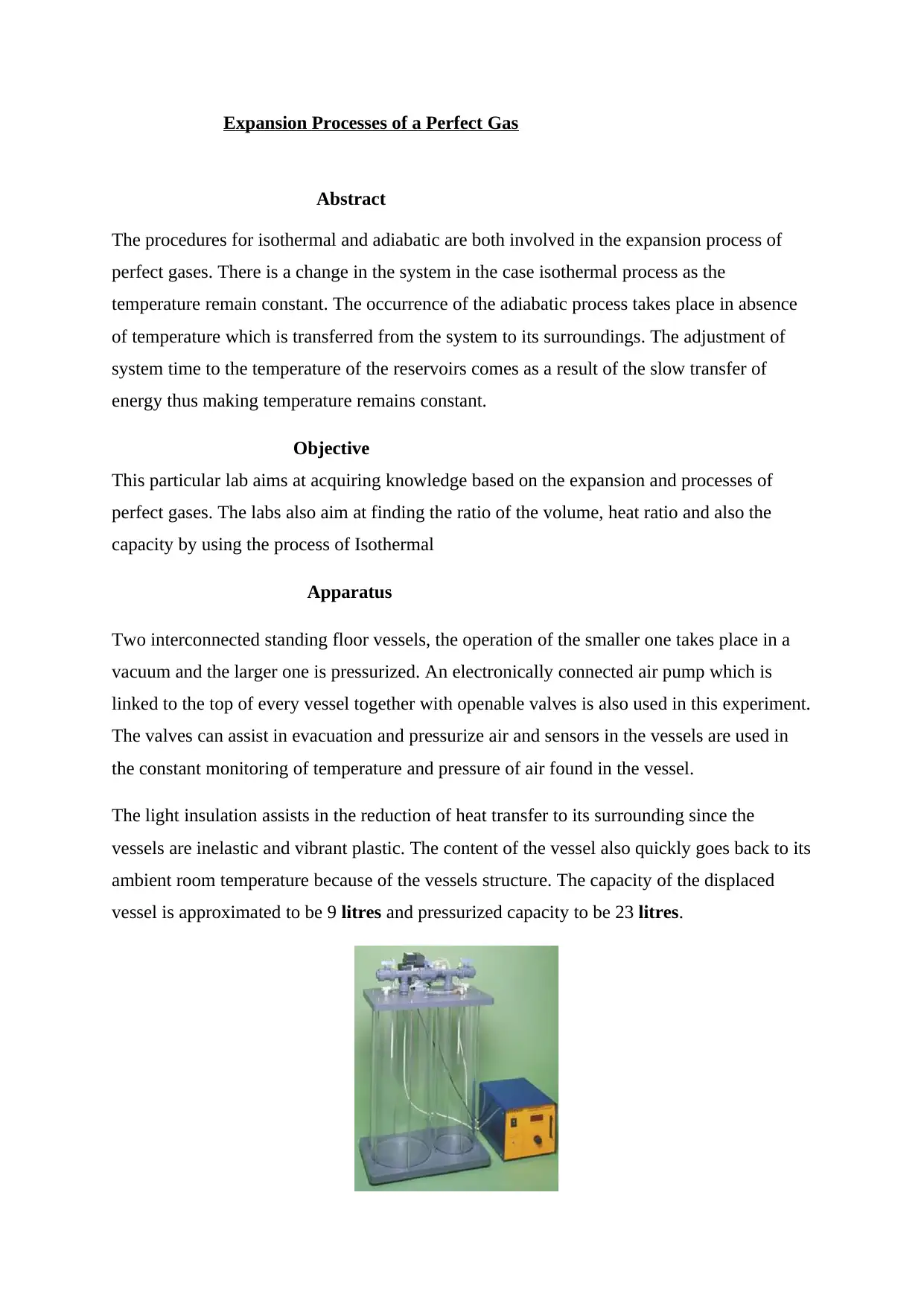
Two interconnected standing floor vessels, the operation of the smaller one takes place in a
vacuum and the larger one is pressurized. An electronically connected air pump which is
linked to the top of every vessel together with openable valves is also used in this experiment.
The valves can assist in evacuation and pressurize air and sensors in the vessels are used in
the constant monitoring of temperature and pressure of air found in the vessel.
The light insulation assists in the reduction of heat transfer to its surrounding since the
vessels are inelastic and vibrant plastic. The content of the vessel also quickly goes back to its
ambient room temperature because of the vessels structure. The capacity of the displaced
vessel is approximated to be 9 litres and pressurized capacity to be 23 litres.
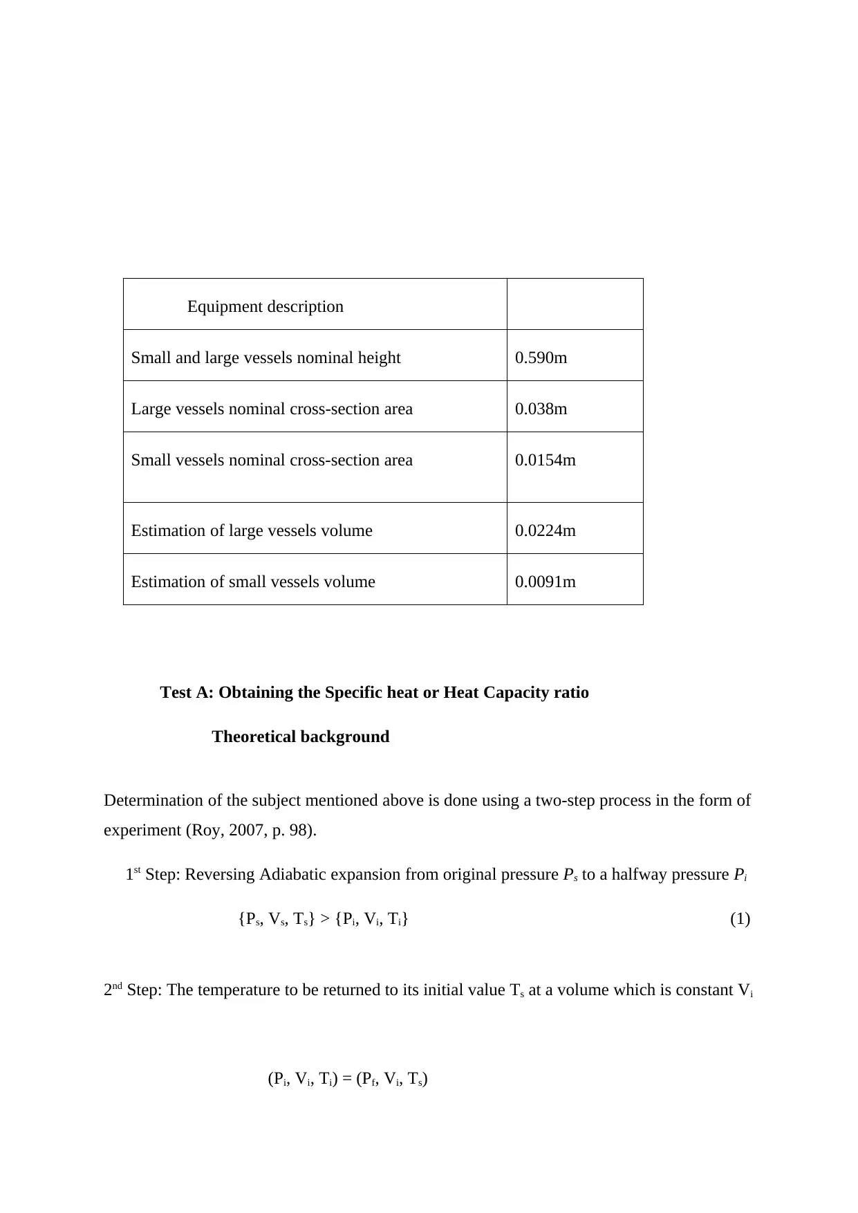
Equipment description
Small and large vessels nominal height 0.590m
Large vessels nominal cross-section area 0.038m
Small vessels nominal cross-section area 0.0154m
Estimation of large vessels volume 0.0224m
Estimation of small vessels volume 0.0091m
Test A: Obtaining the Specific heat or Heat Capacity ratio
Theoretical background
Determination of the subject mentioned above is done using a two-step process in the form of
experiment (Roy, 2007, p. 98).
1st Step: Reversing Adiabatic expansion from original pressure Ps to a halfway pressure Pi
{Ps, Vs, Ts} > {Pi, Vi, Ti} (1)
2nd Step: The temperature to be returned to its initial value Ts at a volume which is constant Vi
(Pi, Vi, Ti) = (Pf, Vi, Ts)
⊘ This is a preview!⊘
Do you want full access?
Subscribe today to unlock all pages.

Trusted by 1+ million students worldwide
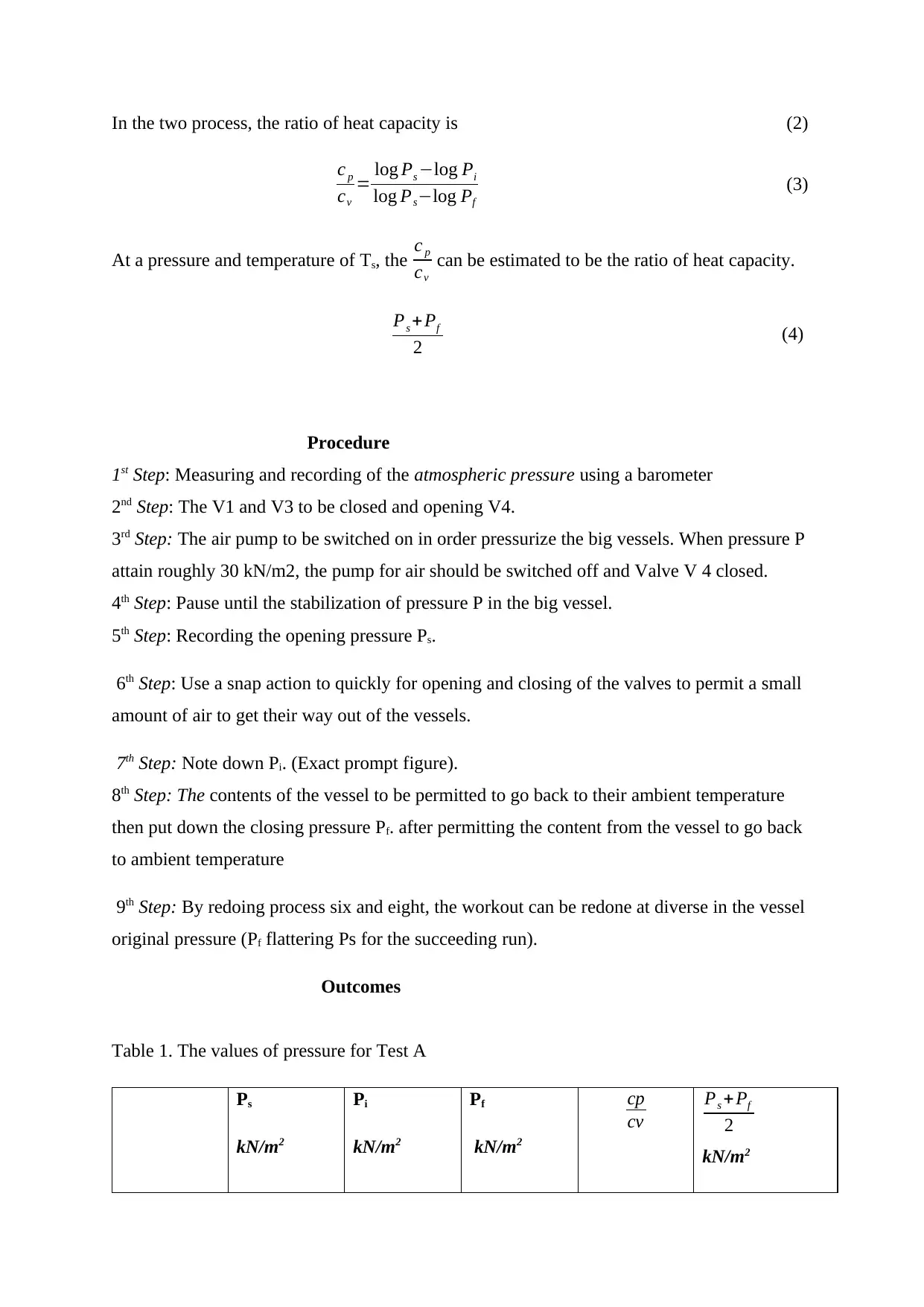
In the two process, the ratio of heat capacity is (2)
c p
cv
= log Ps −log Pi
log Ps−log Pf
(3)
At a pressure and temperature of Ts, the c p
cv
can be estimated to be the ratio of heat capacity.
Ps + Pf
2 (4)
Procedure
1st Step: Measuring and recording of the atmospheric pressure using a barometer
2nd Step: The V1 and V3 to be closed and opening V4.
3rd Step: The air pump to be switched on in order pressurize the big vessels. When pressure P
attain roughly 30 kN/m2, the pump for air should be switched off and Valve V 4 closed.
4th Step: Pause until the stabilization of pressure P in the big vessel.
5th Step: Recording the opening pressure Ps.
6th Step: Use a snap action to quickly for opening and closing of the valves to permit a small
amount of air to get their way out of the vessels.
7th Step: Note down Pi. (Exact prompt figure).
8th Step: The contents of the vessel to be permitted to go back to their ambient temperature
then put down the closing pressure Pf. after permitting the content from the vessel to go back
to ambient temperature
9th Step: By redoing process six and eight, the workout can be redone at diverse in the vessel
original pressure (Pf flattering Ps for the succeeding run).
Outcomes
Table 1. The values of pressure for Test A
Ps
kN/m2
Pi
kN/m2
Pf
kN/m2
cp
cv
Ps +Pf
2
kN/m2
Paraphrase This Document
Need a fresh take? Get an instant paraphrase of this document with our AI Paraphraser
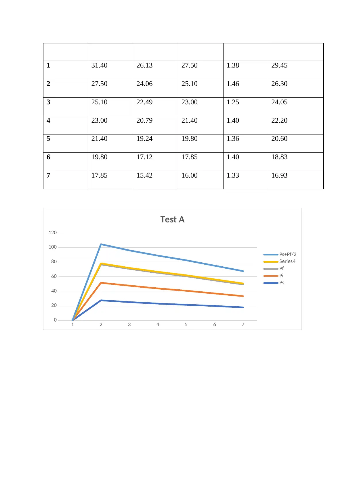
1 31.40 26.13 27.50 1.38 29.45
2 27.50 24.06 25.10 1.46 26.30
3 25.10 22.49 23.00 1.25 24.05
4 23.00 20.79 21.40 1.40 22.20
5 21.40 19.24 19.80 1.36 20.60
6 19.80 17.12 17.85 1.40 18.83
7 17.85 15.42 16.00 1.33 16.93
1 2 3 4 5 6 7
0
20
40
60
80
100
120
Test A
Ps+Pf/2
Series4
Pf
Pi
Ps
2 27.50 24.06 25.10 1.46 26.30
3 25.10 22.49 23.00 1.25 24.05
4 23.00 20.79 21.40 1.40 22.20
5 21.40 19.24 19.80 1.36 20.60
6 19.80 17.12 17.85 1.40 18.83
7 17.85 15.42 16.00 1.33 16.93
1 2 3 4 5 6 7
0
20
40
60
80
100
120
Test A
Ps+Pf/2
Series4
Pf
Pi
Ps
Argument
The reason why minimization and elimination of the transfer of heat in the adiabatic process
are discussed below. The transfer of heat does not occur during expansion and this
demonstration of this was exhibited when the opening of the valve occurs within a short
period of time thereby permitting removal of a substantial amount of air. The closing of
valves the bring to an end the expansion and as a result of this, a minimum value of pressure
drop is realized. The independent pressure drop realized which does not affect the heat
transfer shows that the expansion can be deliberated to be adiabatic (Prasad, 2008, p. 45).
Test B: Using the process of isothermal to determine the volume ratio.
Hypothetical contextual
Centred on the state of ideal gas equivalence, determination of vessels volume ratio can be
gotten by;
V 1
V 2
= P2 s −Pf
Pf −P1 s
(5)
V1 - the large vessel volume
V2 - the small vessel volume
P1s - large vessel original pressure
P2s - the small vessel original pressure
Pf - the two vessels closing pressure
Procedure
The pressurizing of a single vessel is done primarily and permits firmness at ambient
temperature.
1st Step: Measuring and recording of the atmospheric pressure using a barometer.
2nd Step: Turn off the ball valves V5and V3 and Valve V1 while opening the V4.
3rd Step: The air pump is turned on to pressurize the huge vessels. When roughly 30 kN/m2,
is attained by pressure P then, air pump to be switched off Valve V 4 closed.
4th Step: Pose until stabilization in pressure P for the large vessels is achieved. Stay while
⊘ This is a preview!⊘
Do you want full access?
Subscribe today to unlock all pages.

Trusted by 1+ million students worldwide
waiting for pressure P in the large vessel to stabilise (Sato, 2006, p. 234)
5th Step: The primary pressure Ps. to be recorded (Kenny, 2010, p. 45).
6th Step: Confirm the closure of the needle valve V5 fully, then turn on isolating valve V6.
The air should be allowed to leak from large to small vessels by simply opening of Valve
faintly. The V5 to be adjusted to allow falling of pressure P gradually and having no
alteration in T1 or T2 (if there is quick air flow then there will be a change in T1 and T2
A slight opening of Valve 5 to reduce the exercise duration in case there is an increase in the
pressure of small vessels and a decrease in the pressure of large vessels.
The temperature and pressure for the content in the vessels to be allowed to stabilize
afterward the final pressures Pf can be recorded (Singh, 2007, p. 54).
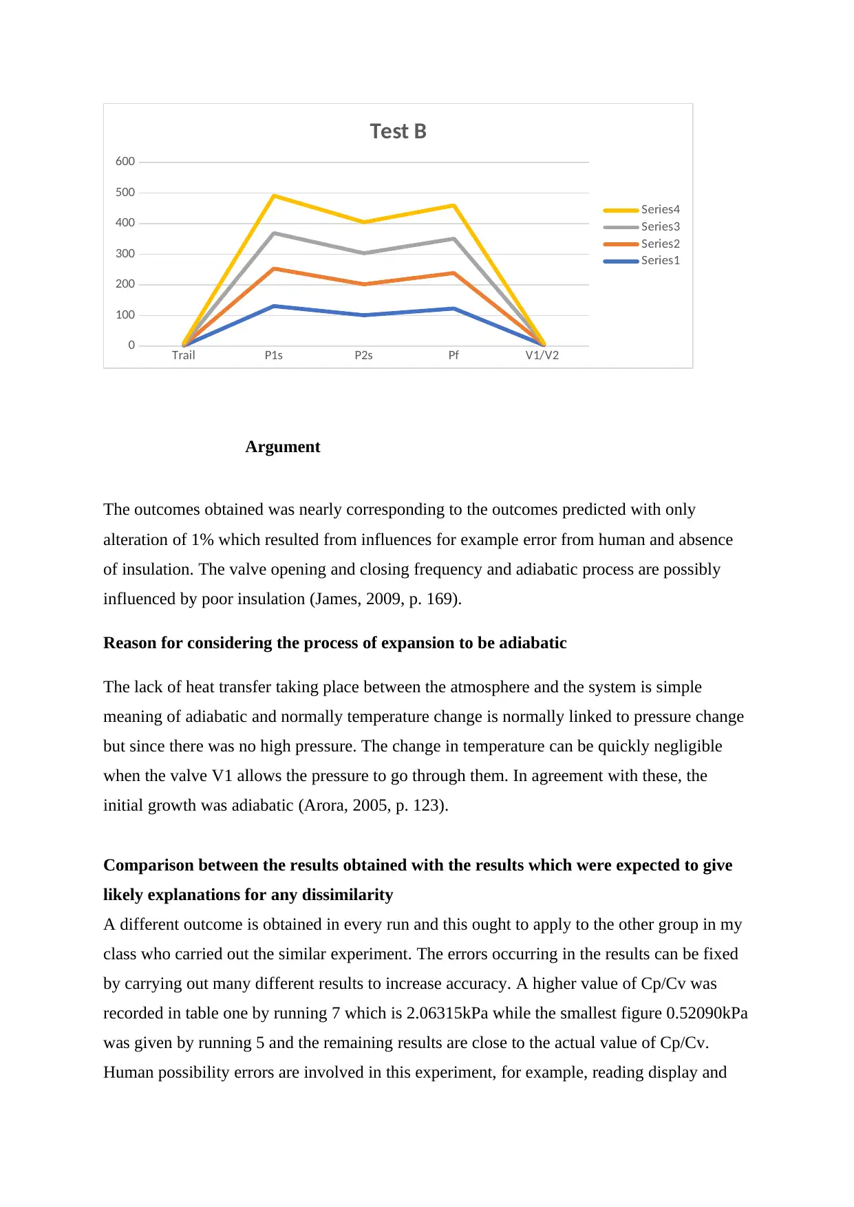
The exercise to be repeated four diverse original pressures in the huge vessels. Illustration of
the pressure readings which occurred is in table 2.
Outcomes
Table 2. The Test B pressure values
T (°C) Patm
kPa
P1s P2s Pf V1/V2
1 30.6 101 130.4 100.44 122.4 2.74
2 30.6 101 122.4 101.23 116 2.30
3 30.6 101 116 101.5 112 2.62
4 30.6 101 122 101.25 109 0.59
Paraphrase This Document
Need a fresh take? Get an instant paraphrase of this document with our AI Paraphraser
Trail P1s P2s Pf V1/V2
0
100
200
300
400
500
600
Test B
Series4
Series3
Series2
Series1
Argument
The outcomes obtained was nearly corresponding to the outcomes predicted with only
alteration of 1% which resulted from influences for example error from human and absence
of insulation. The valve opening and closing frequency and adiabatic process are possibly
influenced by poor insulation (James, 2009, p. 169).
Reason for considering the process of expansion to be adiabatic
The lack of heat transfer taking place between the atmosphere and the system is simple
meaning of adiabatic and normally temperature change is normally linked to pressure change
but since there was no high pressure. The change in temperature can be quickly negligible
when the valve V1 allows the pressure to go through them. In agreement with these, the
initial growth was adiabatic (Arora, 2005, p. 123).
Comparison between the results obtained with the results which were expected to give
likely explanations for any dissimilarity
A different outcome is obtained in every run and this ought to apply to the other group in my
class who carried out the similar experiment. The errors occurring in the results can be fixed
by carrying out many different results to increase accuracy. A higher value of Cp/Cv was
recorded in table one by running 7 which is 2.06315kPa while the smallest figure 0.52090kPa
was given by running 5 and the remaining results are close to the actual value of Cp/Cv.
Human possibility errors are involved in this experiment, for example, reading display and
diverse surrounding conditions which cause a dissimilar percentage error (Adwera, 2009, p.
78).
Remark on how the temperature of the air in the vessel is affected by the change in rate.
Ever reading is recorded every second by setting up transient pressure response on the
computer. IO to take records. Once the system is at equilibrium, then a slow drop until
consistency and unstable readings are realized from the data. As a result, ambient situation,
there no much change in temperature over time. The pumping of air in and out of the pressure
chamber will increase as a result instability in pressure sensor more than temperature sensor.
In the experimentation above, the high drop in pressure more than the drop in temperature
abandon the change in temperature over time (Singh, 2007, p. 56).
CONCLUSION
From the results, it can be concluded that the results that were obtained from the laboratory
and theoretical results were not far off when compared. The process of gas expansion has
been confirmed to follow Gay-Lussac and Boyle laws which relate the conditions and
characteristics for example volume, temperature, and pressure. The results acquired were
steady as illustrated by numerous analyses on pressure.
⊘ This is a preview!⊘
Do you want full access?
Subscribe today to unlock all pages.

Trusted by 1+ million students worldwide
Bibliography
Adwera, P., 2009. Thermal Science and Engineering. s.l.:HarperCollins.
Arora, D., 2005. Thermodynamics. s.l.:Wiley.
James, D., 2009. Kinetic Theory and Thermodynamics. s.l.:Gakken.
Kenny, R., 2010. Comprehensive Elments of Mechanical Engineering. s.l.:Sanoma.
Prasad, M., 2008. An Introduction to Energy Conversion. s.l.:Adventure Works Press.
Roy, B., 2007. Fundamentals of Classical and Statistical Thermodynamics. s.l.:Scholistic.
Sato, N., 2006. Chemical Energy and Exergy. s.l.:Cambridge University Press.
Singh, O., 2007. Applied Thermodynamics. s.l.:OLMA Media Group.
1 out of 10
Your All-in-One AI-Powered Toolkit for Academic Success.
+13062052269
info@desklib.com
Available 24*7 on WhatsApp / Email
![[object Object]](/_next/static/media/star-bottom.7253800d.svg)
Unlock your academic potential
Copyright © 2020–2025 A2Z Services. All Rights Reserved. Developed and managed by ZUCOL.

