University Structures Lab: Timber Bending and Flitch Beam Analysis
VerifiedAdded on 2023/05/28
|13
|1786
|150
Report
AI Summary
This report presents the findings of a structures laboratory experiment investigating the bending behavior of timber beams and the deflection characteristics of flitch beams. The experiment involved testing joist planks, joist beams, and three different flitch beam configurations under inc...
First Name Last Name
Instructor
Course
12 December 2018
Instructor
Course
12 December 2018
Paraphrase This Document
Need a fresh take? Get an instant paraphrase of this document with our AI Paraphraser
Last Name 2
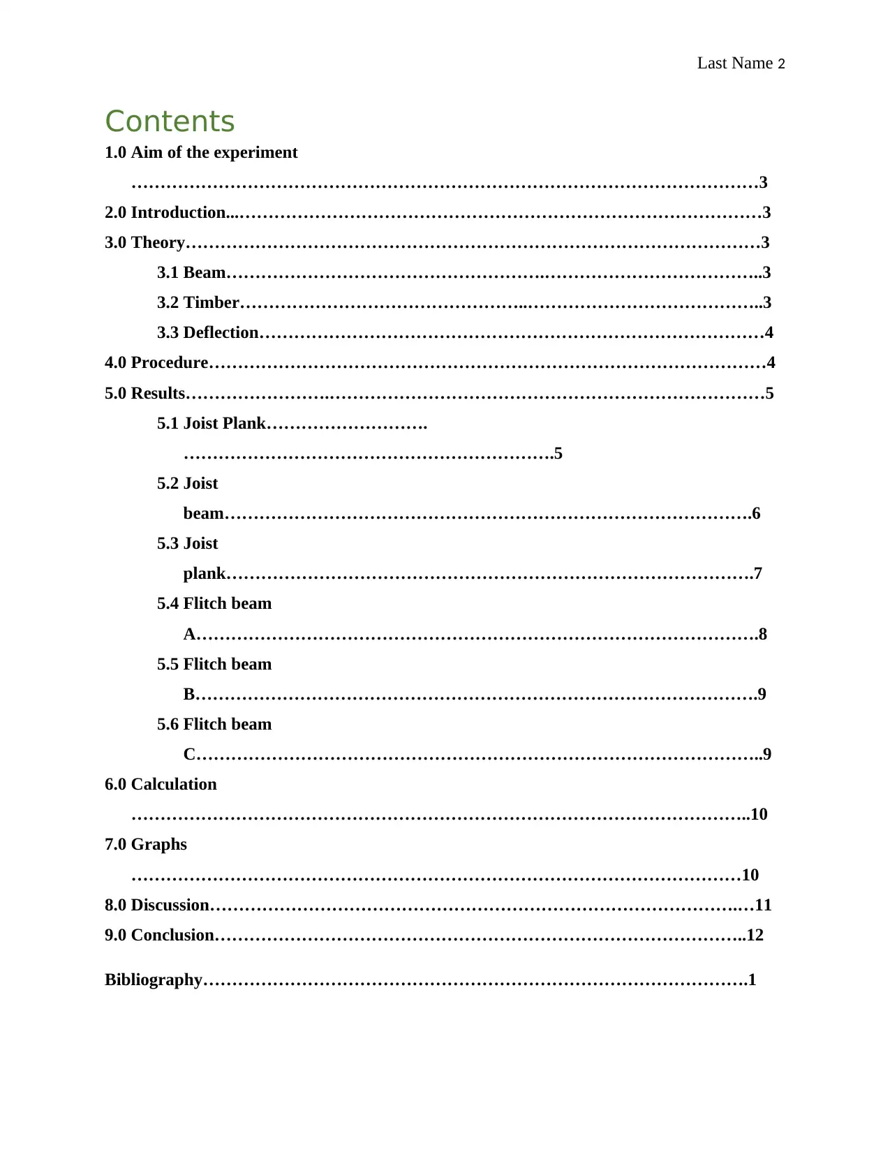
Contents
1.0 Aim of the experiment
………………………………………………………………………………………………3
2.0 Introduction...………………………………………………………………………………3
3.0 Theory………………………………………………………………………………………3
3.1 Beam……………………………………………….………………………………..3
3.2 Timber…………………………………………..…………………………………..3
3.3 Deflection……………………………………………………………………………4
4.0 Procedure……………………………………………………………………………………4
5.0 Results…………………….…………………………………………………………………5
5.1 Joist Plank……………………….
……………………………………………………….5
5.2 Joist
beam……………………………………………………………………………….6
5.3 Joist
plank……………………………………………………………………………….7
5.4 Flitch beam
A…………………………………………………………………………………….8
5.5 Flitch beam
B…………………………………………………………………………………….9
5.6 Flitch beam
C……………………………………………………………………………………..9
6.0 Calculation
……………………………………………………………………………………………..10
7.0 Graphs
……………………………………………………………………………………………10
8.0 Discussion……………………………………………………………………………….…11
9.0 Conclusion………………………………………………………………………………..12
Bibliography………………………………………………………………………………….1
Last Name 3
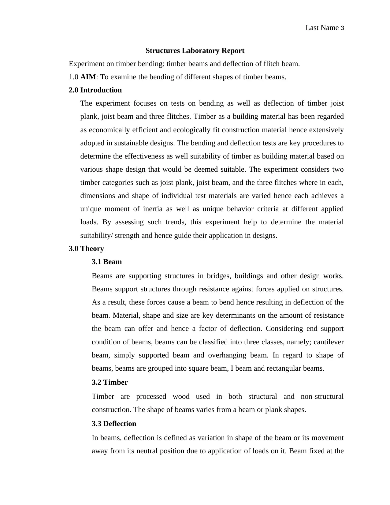
Structures Laboratory Report
Experiment on timber bending: timber beams and deflection of flitch beam.
1.0 AIM: To examine the bending of different shapes of timber beams.
2.0 Introduction
The experiment focuses on tests on bending as well as deflection of timber joist
plank, joist beam and three flitches. Timber as a building material has been regarded
as economically efficient and ecologically fit construction material hence extensively
adopted in sustainable designs. The bending and deflection tests are key procedures to
determine the effectiveness as well suitability of timber as building material based on
various shape design that would be deemed suitable. The experiment considers two
timber categories such as joist plank, joist beam, and the three flitches where in each,
dimensions and shape of individual test materials are varied hence each achieves a
unique moment of inertia as well as unique behavior criteria at different applied
loads. By assessing such trends, this experiment help to determine the material
suitability/ strength and hence guide their application in designs.
3.0 Theory
3.1 Beam
Beams are supporting structures in bridges, buildings and other design works.
Beams support structures through resistance against forces applied on structures.
As a result, these forces cause a beam to bend hence resulting in deflection of the
beam. Material, shape and size are key determinants on the amount of resistance
the beam can offer and hence a factor of deflection. Considering end support
condition of beams, beams can be classified into three classes, namely; cantilever
beam, simply supported beam and overhanging beam. In regard to shape of
beams, beams are grouped into square beam, I beam and rectangular beams.
3.2 Timber
Timber are processed wood used in both structural and non-structural
construction. The shape of beams varies from a beam or plank shapes.
3.3 Deflection
In beams, deflection is defined as variation in shape of the beam or its movement
away from its neutral position due to application of loads on it. Beam fixed at the
⊘ This is a preview!⊘
Do you want full access?
Subscribe today to unlock all pages.

Trusted by 1+ million students worldwide
Last Name 4
end or at either of the ends get displaced away from its positions relative to
loading direction of the beam. The displacement that results is identified as
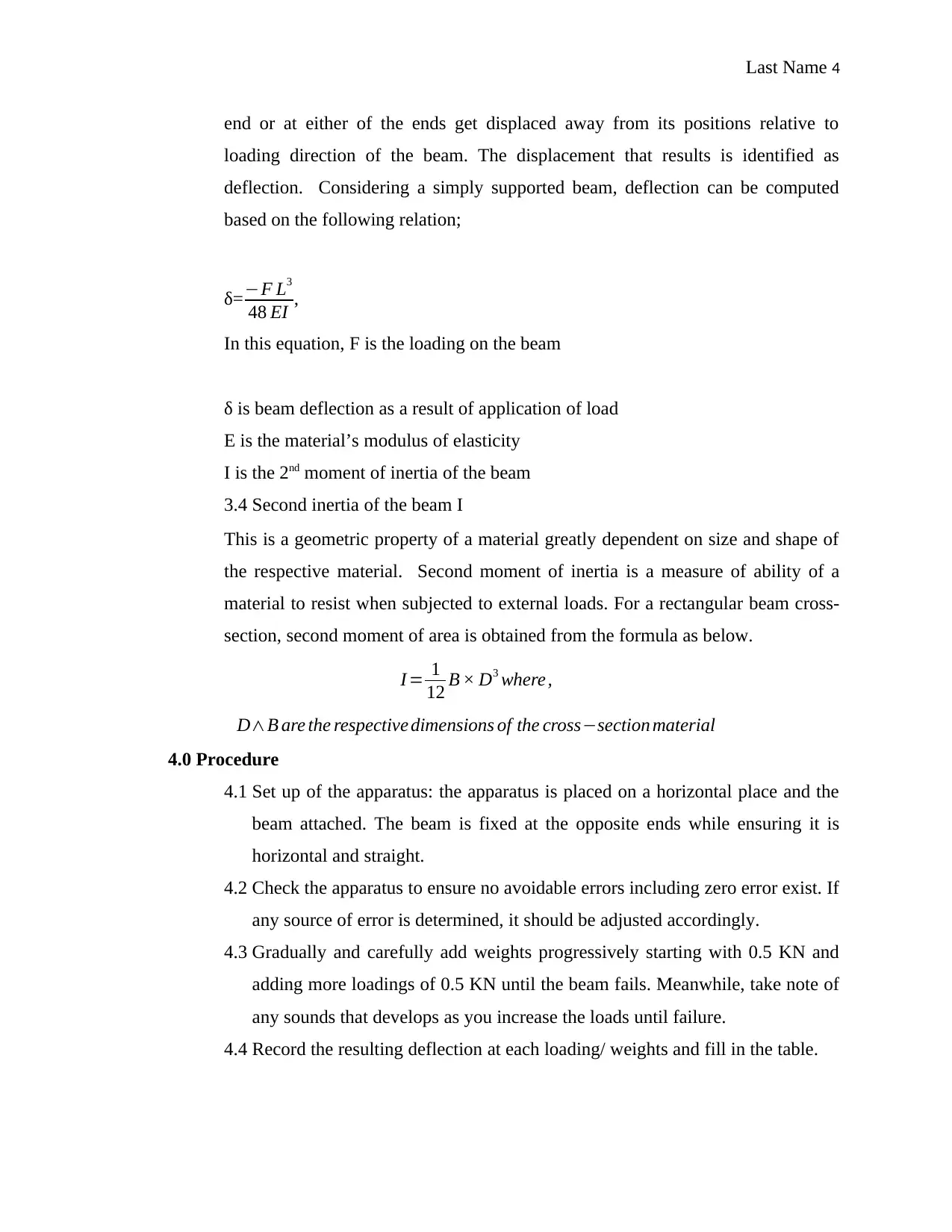
deflection. Considering a simply supported beam, deflection can be computed
based on the following relation;
δ=−F L3
48 EI ,
In this equation, F is the loading on the beam
δ is beam deflection as a result of application of load
E is the material’s modulus of elasticity
I is the 2nd moment of inertia of the beam
3.4 Second inertia of the beam I
This is a geometric property of a material greatly dependent on size and shape of
the respective material. Second moment of inertia is a measure of ability of a
material to resist when subjected to external loads. For a rectangular beam cross-
section, second moment of area is obtained from the formula as below.
I = 1
12 B × D3 where ,
D∧B are the respective dimensions of the cross−section material
4.0 Procedure
4.1 Set up of the apparatus: the apparatus is placed on a horizontal place and the
beam attached. The beam is fixed at the opposite ends while ensuring it is
horizontal and straight.
4.2 Check the apparatus to ensure no avoidable errors including zero error exist. If
any source of error is determined, it should be adjusted accordingly.
4.3 Gradually and carefully add weights progressively starting with 0.5 KN and
adding more loadings of 0.5 KN until the beam fails. Meanwhile, take note of
any sounds that develops as you increase the loads until failure.
4.4 Record the resulting deflection at each loading/ weights and fill in the table.
Paraphrase This Document
Need a fresh take? Get an instant paraphrase of this document with our AI Paraphraser
Last Name 5
4.5 Replicate the above steps for 3 dissimilar shapes of flitch beam and for plank
shape.
5.0 Results
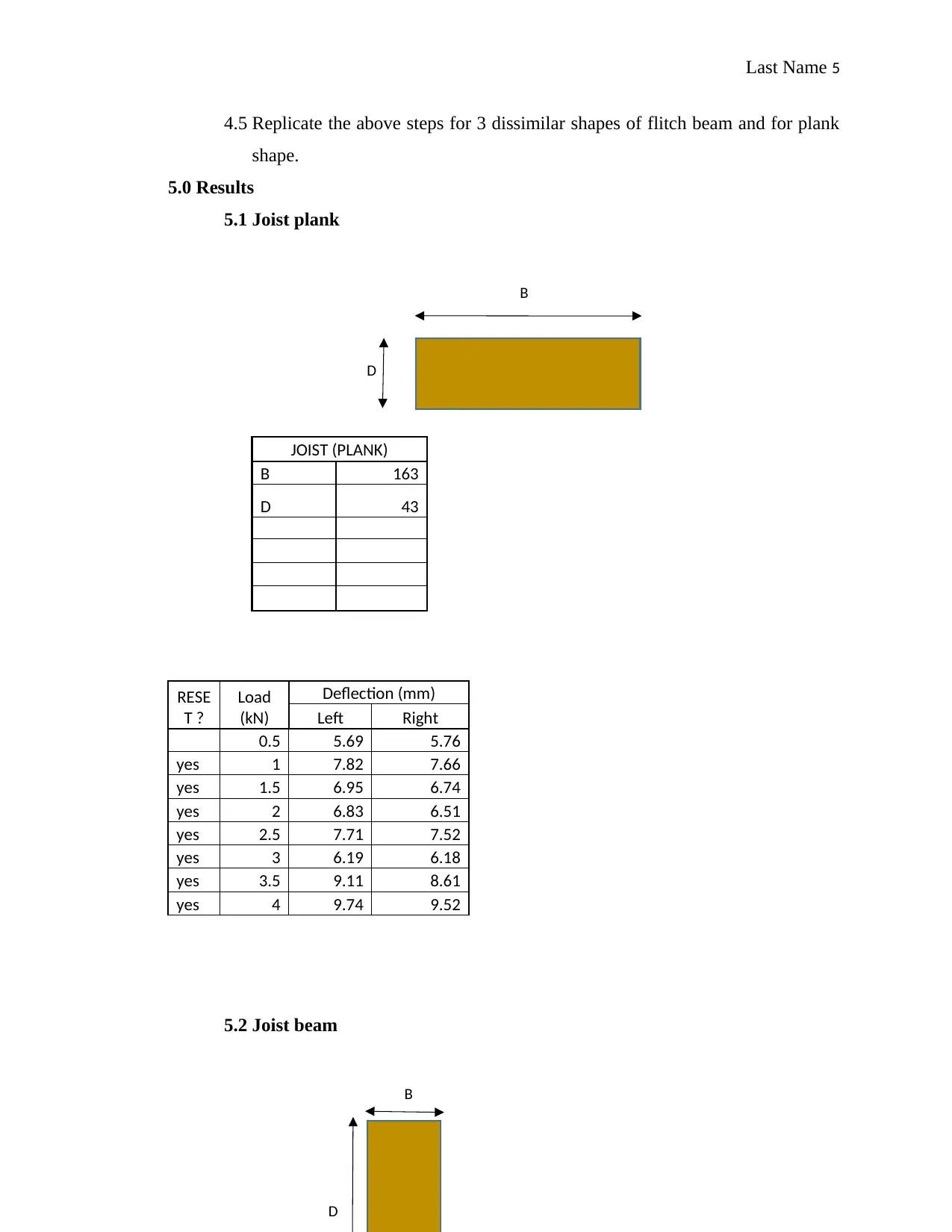
5.1 Joist plank
JOIST (PLANK)
B 163
D 43
RESE
T ?
Load
(kN)
Deflection (mm)
Left Right
0.5 5.69 5.76
yes 1 7.82 7.66
yes 1.5 6.95 6.74
yes 2 6.83 6.51
yes 2.5 7.71 7.52
yes 3 6.19 6.18
yes 3.5 9.11 8.61
yes 4 9.74 9.52
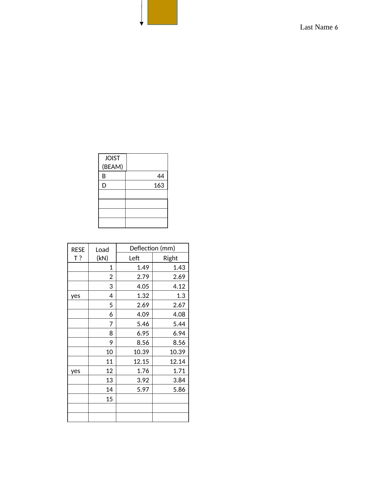
5.2 Joist beam
B
D
B
D
Last Name 6
JOIST
(BEAM)
B 44
D 163
RESE
T ?
Load
(kN)
Deflection (mm)
Left Right
1 1.49 1.43
2 2.79 2.69
3 4.05 4.12
yes 4 1.32 1.3
5 2.69 2.67
6 4.09 4.08
7 5.46 5.44
8 6.95 6.94
9 8.56 8.56
10 10.39 10.39
11 12.15 12.14
yes 12 1.76 1.71
13 3.92 3.84
14 5.97 5.86
15
JOIST
(BEAM)
B 44
D 163
RESE
T ?
Load
(kN)
Deflection (mm)
Left Right
1 1.49 1.43
2 2.79 2.69
3 4.05 4.12
yes 4 1.32 1.3
5 2.69 2.67
6 4.09 4.08
7 5.46 5.44
8 6.95 6.94
9 8.56 8.56
10 10.39 10.39
11 12.15 12.14
yes 12 1.76 1.71
13 3.92 3.84
14 5.97 5.86
15
⊘ This is a preview!⊘
Do you want full access?
Subscribe today to unlock all pages.

Trusted by 1+ million students worldwide
Last Name 7
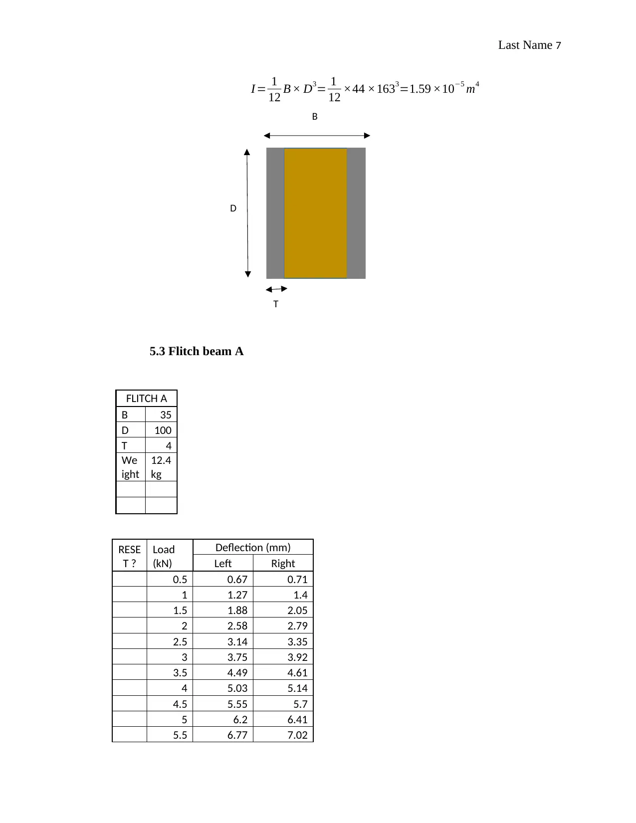
I = 1
12 B × D3= 1
12 ×44 ×1633=1.59 ×10⁻⁵ m4
5.3 Flitch beam A
FLITCH A
B 35
D 100
T 4
We
ight
12.4
kg
RESE
T ?
Load
(kN)
Deflection (mm)
Left Right
0.5 0.67 0.71
1 1.27 1.4
1.5 1.88 2.05
2 2.58 2.79
2.5 3.14 3.35
3 3.75 3.92
3.5 4.49 4.61
4 5.03 5.14
4.5 5.55 5.7
5 6.2 6.41
5.5 6.77 7.02
D
B
T
I = 1
12 B × D3= 1
12 ×44 ×1633=1.59 ×10⁻⁵ m4
5.3 Flitch beam A
FLITCH A
B 35
D 100
T 4
We
ight
12.4
kg
RESE
T ?
Load
(kN)
Deflection (mm)
Left Right
0.5 0.67 0.71
1 1.27 1.4
1.5 1.88 2.05
2 2.58 2.79
2.5 3.14 3.35
3 3.75 3.92
3.5 4.49 4.61
4 5.03 5.14
4.5 5.55 5.7
5 6.2 6.41
5.5 6.77 7.02
D
B
T
Paraphrase This Document
Need a fresh take? Get an instant paraphrase of this document with our AI Paraphraser
Last Name 8
6 7.46 7.74
6.5 8.21 8.58
7 11.09 11.48
yes 7.5 1.49 1.63
8 8.78 8.71
8.5 11.43 11.3
yes 9 3.55 3.62
9.5 6.57 6.61
10 10.96 10.92
yes 10.5 9.6 9.69
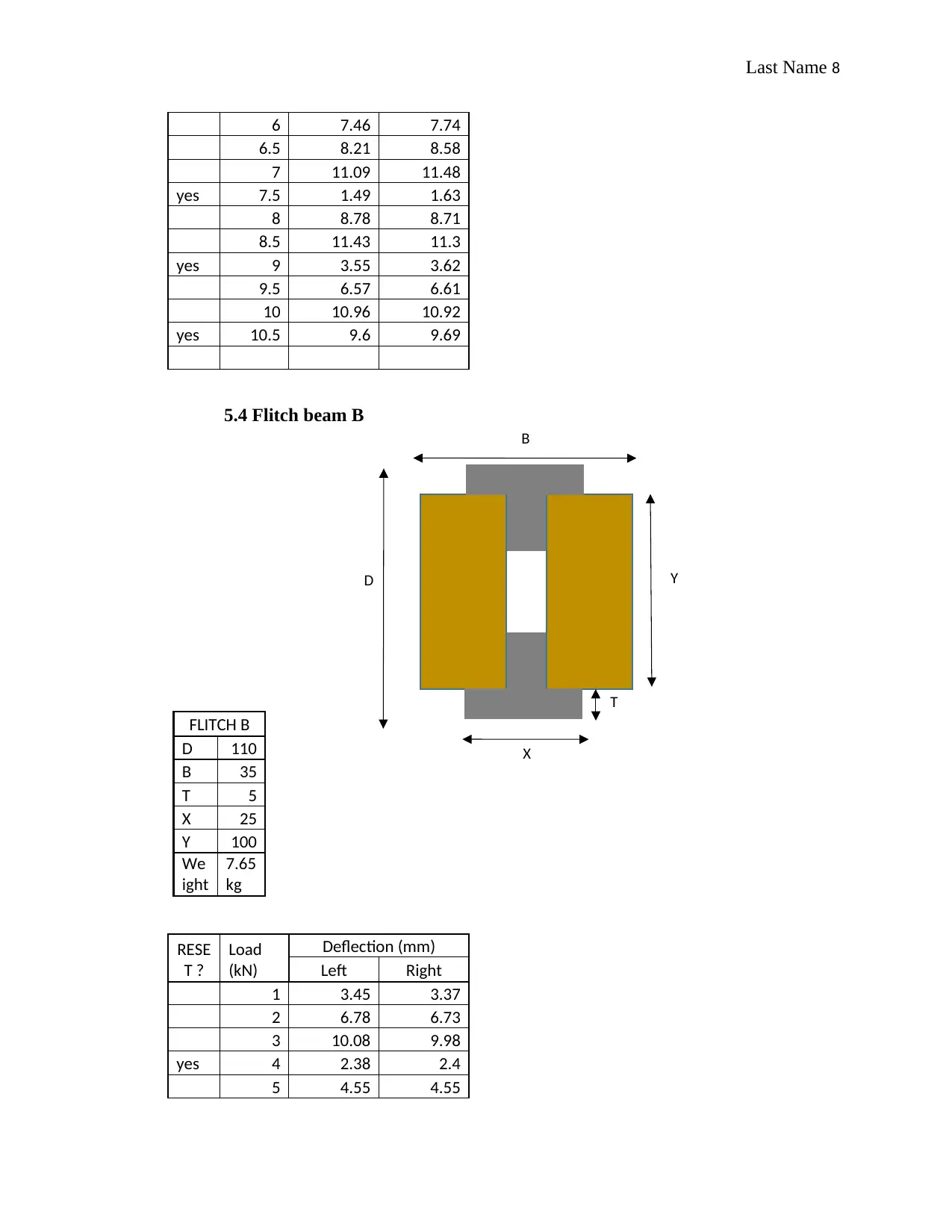
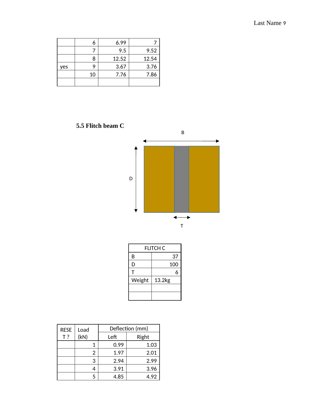
5.4 Flitch beam B
FLITCH B
D 110
B 35
T 5
X 25
Y 100
We
ight
7.65
kg
RESE
T ?
Load
(kN)
Deflection (mm)
Left Right
1 3.45 3.37
2 6.78 6.73
3 10.08 9.98
yes 4 2.38 2.4
5 4.55 4.55
B
D
T
Y
X
Last Name 9
6 6.99 7
7 9.5 9.52
8 12.52 12.54
yes 9 3.67 3.76
10 7.76 7.86
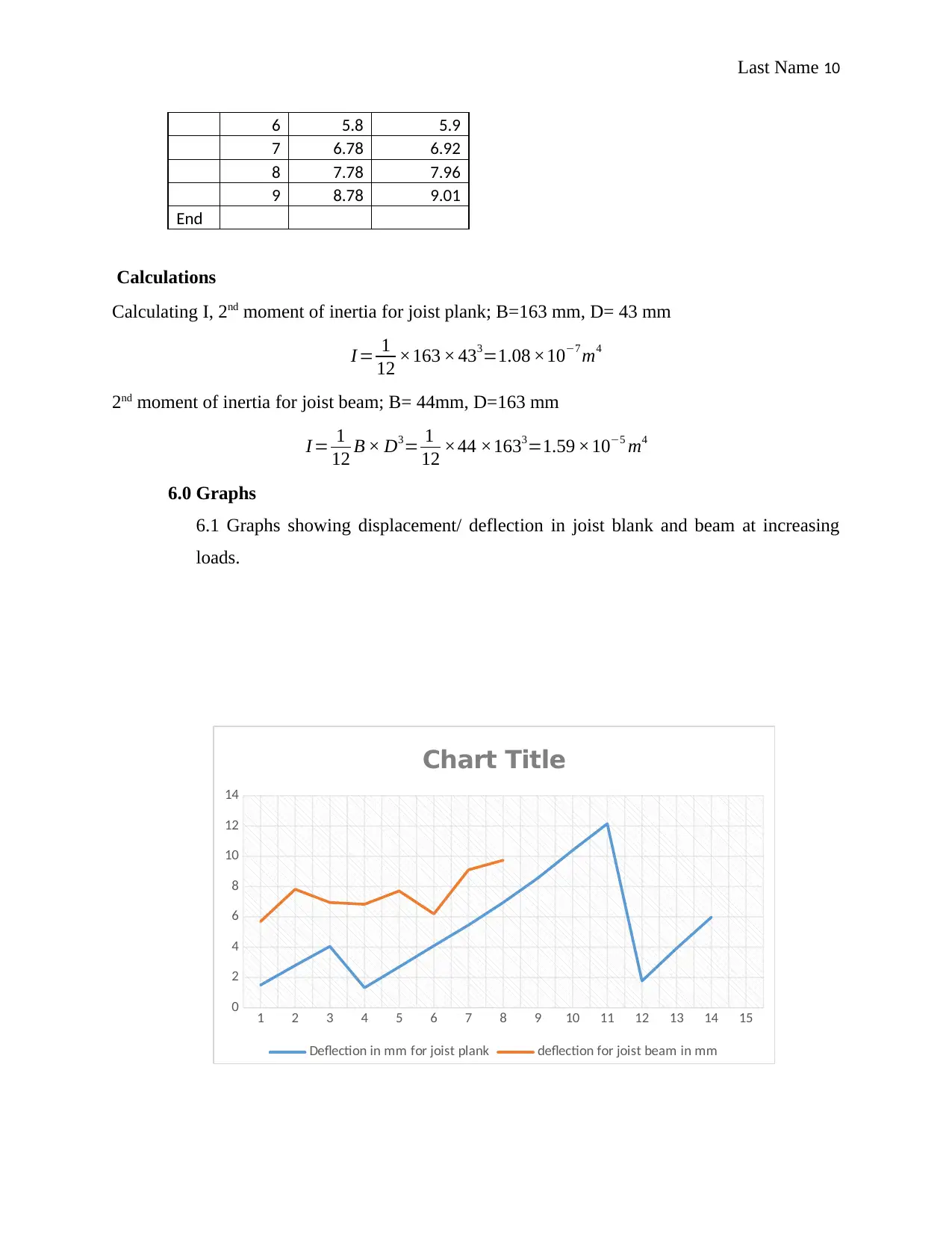
5.5 Flitch beam C
FLITCH C
B 37
D 100
T 6
Weight 13.2kg
RESE
T ?
Load
(kN)
Deflection (mm)
Left Right
1 0.99 1.03
2 1.97 2.01
3 2.94 2.99
4 3.91 3.96
5 4.85 4.92
B
D
T
6 6.99 7
7 9.5 9.52
8 12.52 12.54
yes 9 3.67 3.76
10 7.76 7.86
5.5 Flitch beam C
FLITCH C
B 37
D 100
T 6
Weight 13.2kg
RESE
T ?
Load
(kN)
Deflection (mm)
Left Right
1 0.99 1.03
2 1.97 2.01
3 2.94 2.99
4 3.91 3.96
5 4.85 4.92
B
D
T
⊘ This is a preview!⊘
Do you want full access?
Subscribe today to unlock all pages.

Trusted by 1+ million students worldwide
Last Name 10
6 5.8 5.9
7 6.78 6.92
8 7.78 7.96
9 8.78 9.01
End
Calculations
Calculating I, 2nd moment of inertia for joist plank; B=163 mm, D= 43 mm
I = 1
12 ×163 × 433=1.08 ×10⁻⁷ m4
2nd moment of inertia for joist beam; B= 44mm, D=163 mm
I = 1
12 B × D3= 1
12 ×44 ×1633=1.59 ×10⁻⁵ m4
6.0 Graphs
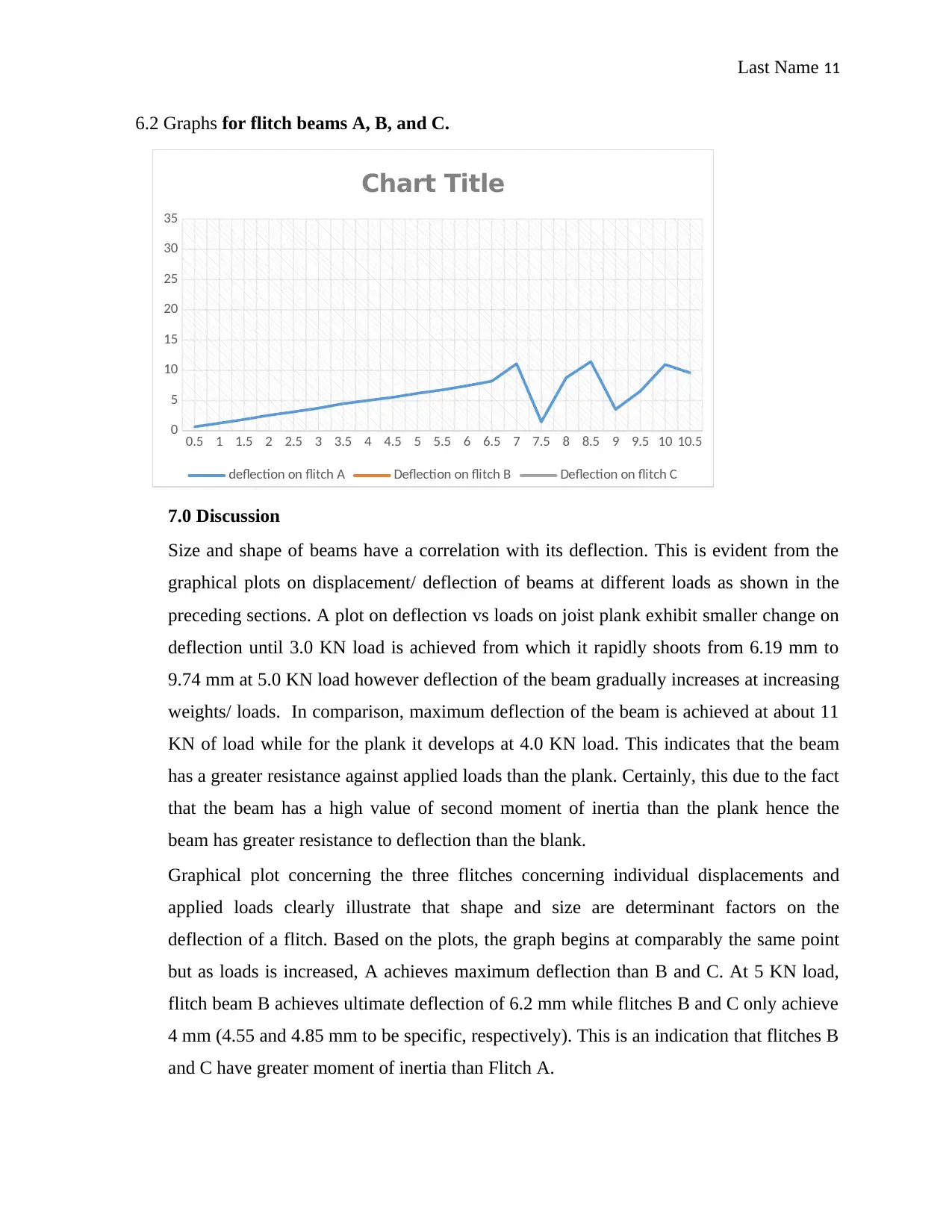
6.1 Graphs showing displacement/ deflection in joist blank and beam at increasing
loads.
1 2 3 4 5 6 7 8 9 10 11 12 13 14 15
0
2
4
6
8
10
12
14
Chart Title
Deflection in mm for joist plank deflection for joist beam in mm
Paraphrase This Document
Need a fresh take? Get an instant paraphrase of this document with our AI Paraphraser
Last Name 11
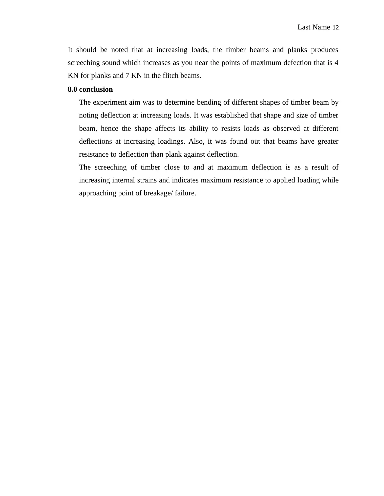
6.2 Graphs for flitch beams A, B, and C.
7.0 Discussion
Size and shape of beams have a correlation with its deflection. This is evident from the
graphical plots on displacement/ deflection of beams at different loads as shown in the
preceding sections. A plot on deflection vs loads on joist plank exhibit smaller change on
deflection until 3.0 KN load is achieved from which it rapidly shoots from 6.19 mm to
9.74 mm at 5.0 KN load however deflection of the beam gradually increases at increasing
weights/ loads. In comparison, maximum deflection of the beam is achieved at about 11
KN of load while for the plank it develops at 4.0 KN load. This indicates that the beam
has a greater resistance against applied loads than the plank. Certainly, this due to the fact
that the beam has a high value of second moment of inertia than the plank hence the
beam has greater resistance to deflection than the blank.
Graphical plot concerning the three flitches concerning individual displacements and
applied loads clearly illustrate that shape and size are determinant factors on the
deflection of a flitch. Based on the plots, the graph begins at comparably the same point
but as loads is increased, A achieves maximum deflection than B and C. At 5 KN load,
flitch beam B achieves ultimate deflection of 6.2 mm while flitches B and C only achieve
4 mm (4.55 and 4.85 mm to be specific, respectively). This is an indication that flitches B
and C have greater moment of inertia than Flitch A.
0.5 1 1.5 2 2.5 3 3.5 4 4.5 5 5.5 6 6.5 7 7.5 8 8.5 9 9.5 10 10.5
0
5
10
15
20
25
30
35
Chart Title
deflection on flitch A Deflection on flitch B Deflection on flitch C
Last Name 12
It should be noted that at increasing loads, the timber beams and planks produces
screeching sound which increases as you near the points of maximum defection that is 4
KN for planks and 7 KN in the flitch beams.
8.0 conclusion
The experiment aim was to determine bending of different shapes of timber beam by
noting deflection at increasing loads. It was established that shape and size of timber
beam, hence the shape affects its ability to resists loads as observed at different
deflections at increasing loadings. Also, it was found out that beams have greater
resistance to deflection than plank against deflection.
The screeching of timber close to and at maximum deflection is as a result of
increasing internal strains and indicates maximum resistance to applied loading while
approaching point of breakage/ failure.
⊘ This is a preview!⊘
Do you want full access?
Subscribe today to unlock all pages.

Trusted by 1+ million students worldwide
Last Name 13
Bibliography
Abdullah, R., 2008. Mechanical properties and bending strength theory for
Malaysian structural timber. Skudai, Johor: Penerbit Universiti Teknologi Malaysia.
Wood-based panels. Determination of modulus of elasticity in bending and of
bending strength, 2016, 154–201.
Bibliography
Abdullah, R., 2008. Mechanical properties and bending strength theory for
Malaysian structural timber. Skudai, Johor: Penerbit Universiti Teknologi Malaysia.
Wood-based panels. Determination of modulus of elasticity in bending and of
bending strength, 2016, 154–201.
1 out of 13
Related Documents
Your All-in-One AI-Powered Toolkit for Academic Success.
+13062052269
info@desklib.com
Available 24*7 on WhatsApp / Email
![[object Object]](/_next/static/media/star-bottom.7253800d.svg)
Unlock your academic potential
© 2024 | Zucol Services PVT LTD | All rights reserved.


