logo

Fan Blade Damage Tolerance Analysis

This unit is assessed by a report containing two pieces of coursework of equal weighting (50%). The coursework draws on experience from industrial consulting work on the application of fracture mechanics and creep-fatigue analysis, and is aimed at providing a realistic opportunity for work experience at engineering consulting in some of the key areas of structural integrity assessment.

21 Pages4028 Words13 Views
   

Added on  2022-08-22

Fan Blade Damage Tolerance Analysis

This unit is assessed by a report containing two pieces of coursework of equal weighting (50%). The coursework draws on experience from industrial consulting work on the application of fracture mechanics and creep-fatigue analysis, and is aimed at providing a realistic opportunity for work experience at engineering consulting in some of the key areas of structural integrity assessment.

   Added on 2022-08-22

ShareRelated Documents
Surname 1
Student Name
Professors Name
Course Title
Date
Part A: Fan Blade Damage Tolerance Analysis.
INTRODUCTION
Aircraft components are usually made of super-alloys with outstanding strengths to improve their
reliability during the service operation. However, different factors affect the life of these
components, such as service-induced degradation and material defects during manufacturing.
The fan blades of an aero-engine have severe operating conditions that influence their life. They
undergo high mechanical stresses from vibratory, centrifugal, and flexural stresses and high
thermal stresses from the high temperature in their operating environment [1].
Damage tolerance analysis must be performed to identify the possible causes of fan-blade failure.
Metallurgical examinations and mechanical analyses are both integrated in investigating the
aero-engine fan blade damage tolerance. The low-cyclic fatigue (LCF) and high-cyclic fatigue
(HCF) damages are considered in combination during structural integrity assessment of the fan
blades. This paper emphasizes on the analytical analysis of aero-engine’s fan blades made of Ti-
6Al-4V alloy by the use of fracture mechanics analysis principles [2].
Fan Blade Damage Tolerance Analysis_1
Surname 2
LITERATURE REVIEW
Metals exhibit damage when subjected to repeated cyclic-loading due to fatigue. The stress
magnitudes in a single load cycle may not be sufficient to cause material failure. However,
repeated cyclic loading ultimately leads to a fatigue failure. Crack initiation, followed by its
propagation under operating load, may lead to rupture when the crack exceeds a critical crack
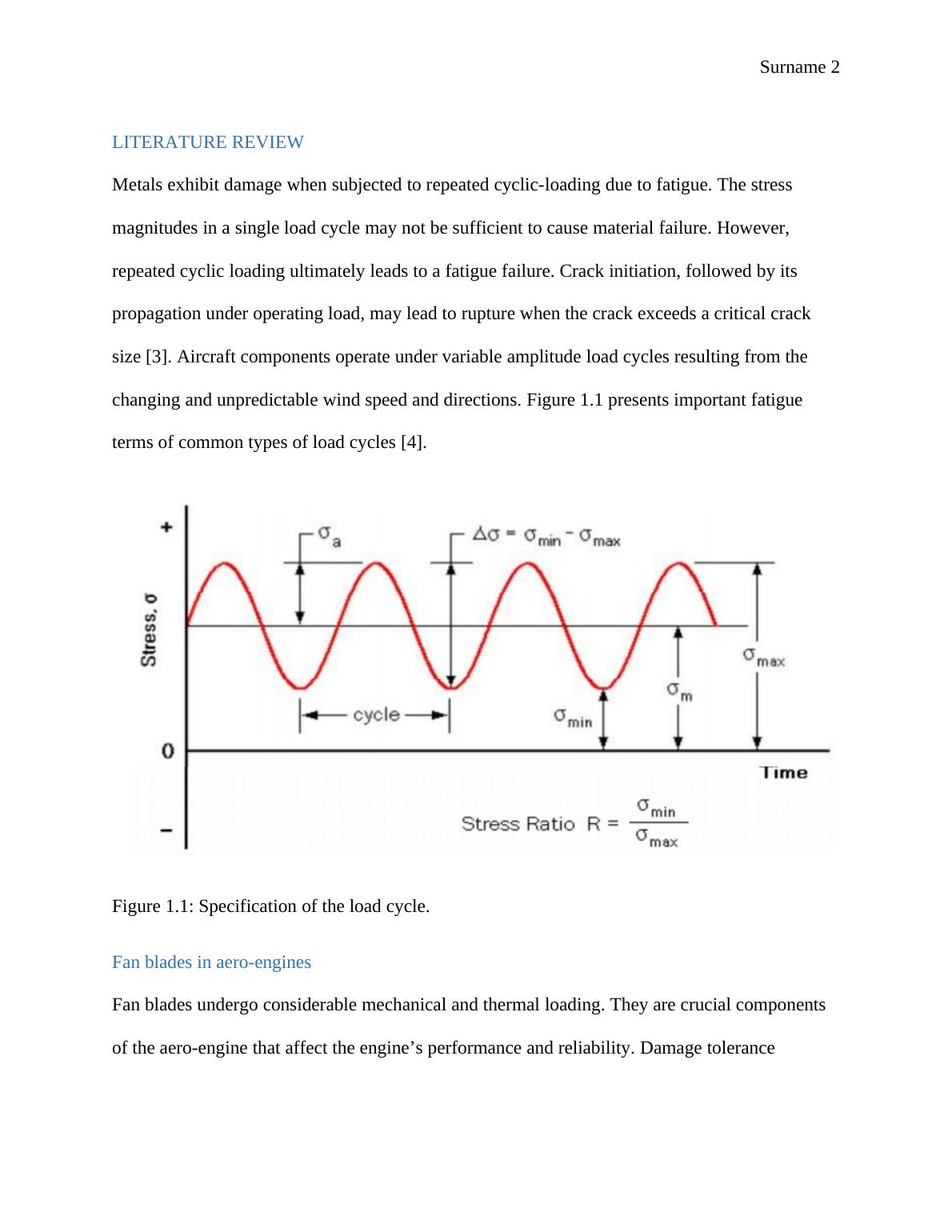
size [3]. Aircraft components operate under variable amplitude load cycles resulting from the
changing and unpredictable wind speed and directions. Figure 1.1 presents important fatigue
terms of common types of load cycles [4].
Figure 1.1: Specification of the load cycle.
Fan blades in aero-engines
Fan blades undergo considerable mechanical and thermal loading. They are crucial components
of the aero-engine that affect the engine’s performance and reliability. Damage tolerance
Fan Blade Damage Tolerance Analysis_2
Surname 3
analysis of the fan blades has been the focus of research works since a fan blade failure can cause
a puncture to the engine and consequently affect the performance and safety of the aircraft [8].
The common failures in fan blades of aero-engines are due to mechanical damage, damage due
to high-temperature exposure, and creep failures. More profound knowledge and understanding
are gained on the damage tolerance of the fan blades through investigations of the crack
initiation and propagation mechanisms. High Cyclic fatigue (HCF) and Low Cycle fatigue (LCF)
failures often occur in the rotating parts, such as the fan blades [9].
Effects of small defects on fatigue thresholds.
In fracture mechanics, defects in the material are considered in structural integrity assessment.
Determination of the strain release rate and the stress integrity factor is possible from the
knowledge of applied stress and the different sizes of the defects. The most commonly used
fracture mechanics method is the linear elastic fracture mechanics (LEFM), which is based on
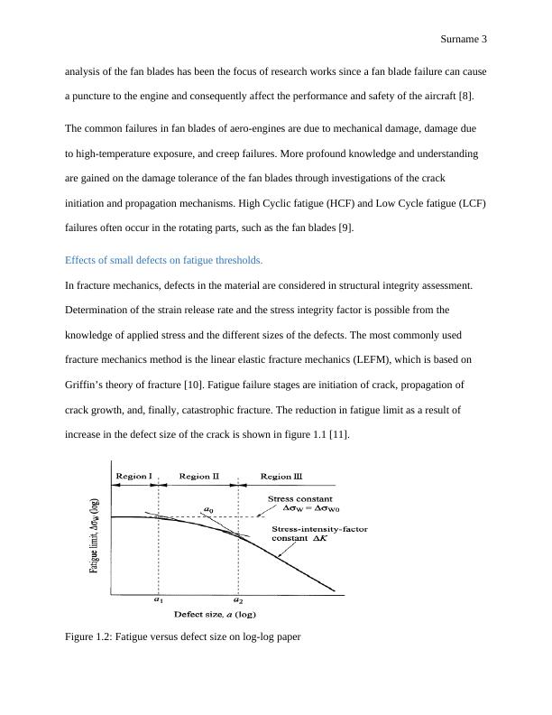
Griffin’s theory of fracture [10]. Fatigue failure stages are initiation of crack, propagation of
crack growth, and, finally, catastrophic fracture. The reduction in fatigue limit as a result of
increase in the defect size of the crack is shown in figure 1.1 [11].
Figure 1.2: Fatigue versus defect size on log-log paper
Fan Blade Damage Tolerance Analysis_3
Surname 4
METHODS
Damage tolerance analysis is used to devise inspection schedules based on the following criteria:
i. The assumed initial damage condition of the fan blade which in this case is assumed
as a center-cracked plate [12]
ii. The fatigue and maximum operational stresses in the fan blade that cause crack
growth from the assumed damaged condition. The fan blade is considered to
experience a uniformly distributed tensile stress.
iii. The fan blade geometry.
iv. Critical crack size beyond which catastrophic failure occurs.
v. Acceptable level of risk [13]
Material properties and fatigue calculations
The Ti-6Al-4V alloy is composed of Ti (89.137 wt%), Al(6.30 %), Fe(0.19 %), N(0.013 %),
O(0.19 %) and V(4.17 %). From the ASM material datasheet, Ti6-4 has a fatigue strength of 240
MPa at stress concentration factor of Kt=5.3. Considering that the blade is modelled as a
rectangular plate of width, W equals 500mm and defect size, 2a of 0.5mm, the following stress
calculations can be made [14].
Maximum stress acting on the blade:
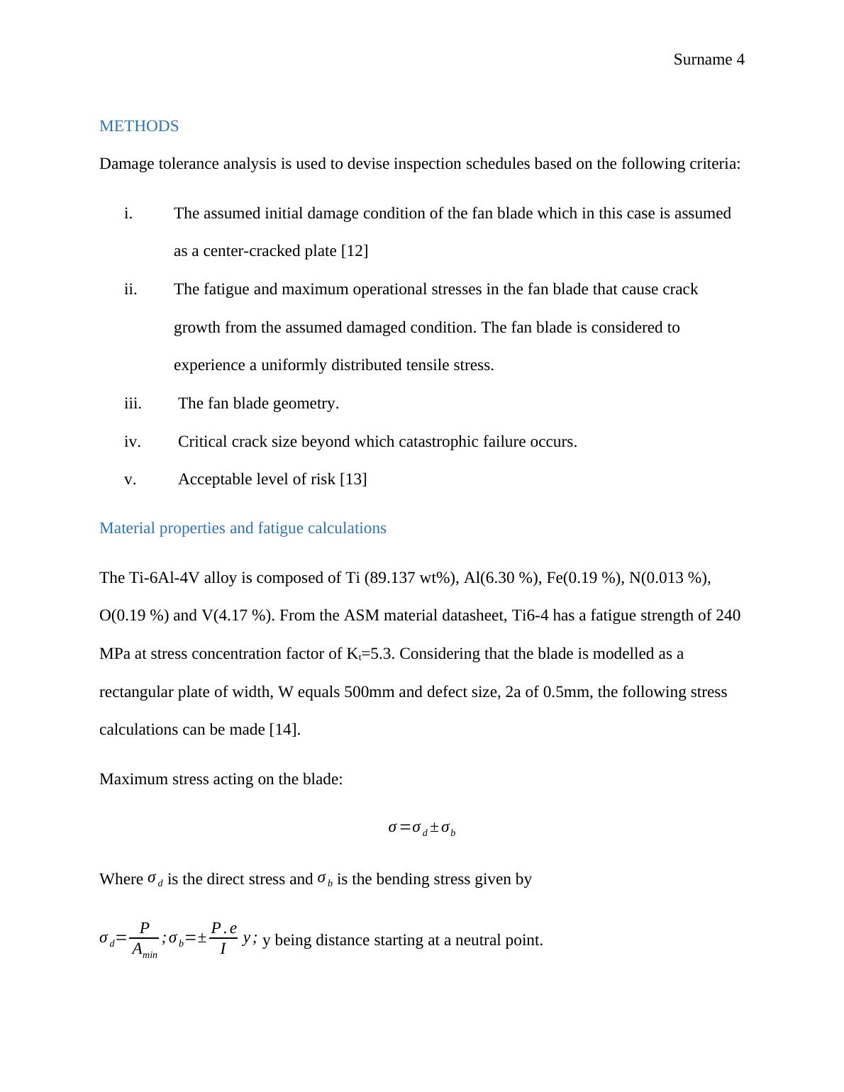
σ =σ d ± σb
Where σ d is the direct stress and σ b is the bending stress given by
σ d= P
Amin
; σ b=± P . e
I y ; y being distance starting at a neutral point.
Fan Blade Damage Tolerance Analysis_4
Surname 5
Amin=W × a=500 × 0.5
2 =125 m m2 from the given dimensions [15].
y
I = 60
W 2 t = 60
5002 × 0.5
2
=9.6 ×10⁴
for Ti-6Al-4V alloy.
Assuming a load of P=5 kN, the direct and the bending stress can be calculated as:
σ d= 5000
125 =40 MPa
And
σ b=± P. e ( y
I )= (5000 × 0.25 ) × 9.6 ×104=1.2 MPa
σ =40+ 1.2=41.2 MPa
Since the blade is considered to be center-cracked, high stress concentrations exist near the
notch. Maximum stress at the notch is obtained from the acting stress on the fan blade and the
stress concentration factor, Kt [16].
σ max=kt σ
σ max=5.3 × 41.2=218.36 MPa
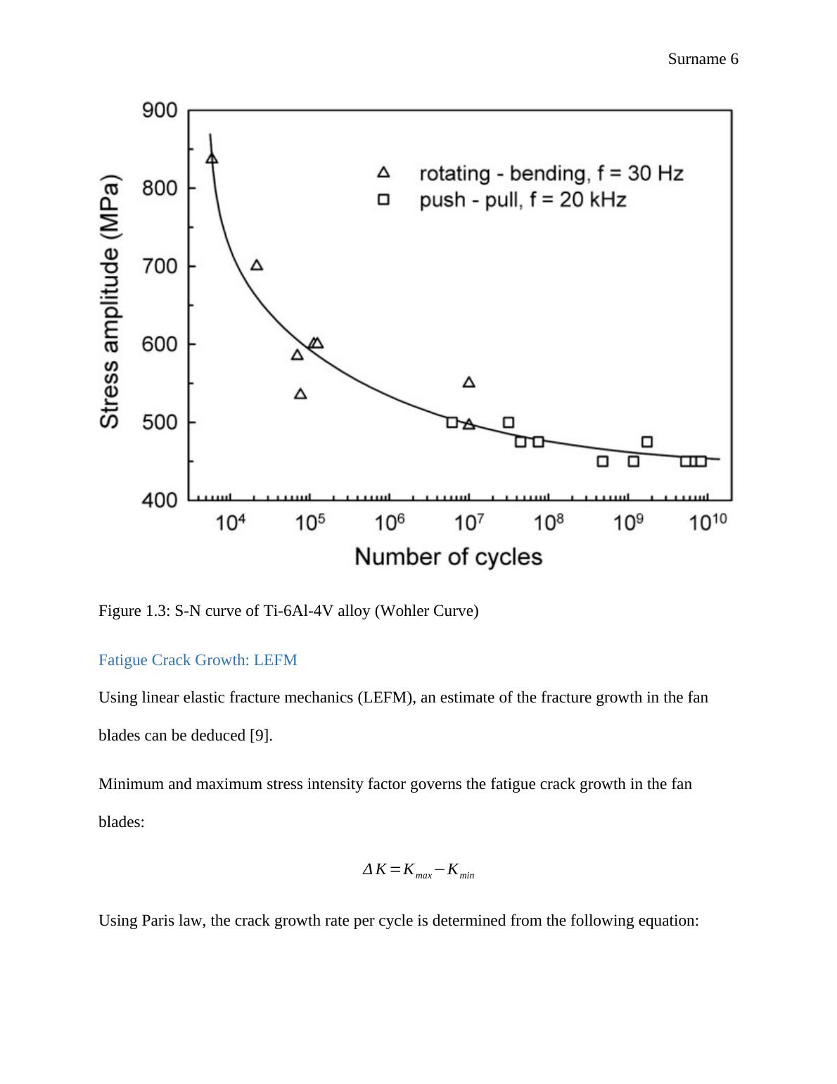
The alternating stress, sn is given by:
sn=a Nb
Where a and b are constants for the Ti-6Al-4V alloy and N are the cycles number.
The figure 1.3 below shows the curve of stress against number of cycles for Ti6-4 material used.
Fan Blade Damage Tolerance Analysis_5
Surname 6
Figure 1.3: S-N curve of Ti-6Al-4V alloy (Wohler Curve)
Fatigue Crack Growth: LEFM
Using linear elastic fracture mechanics (LEFM), an estimate of the fracture growth in the fan
blades can be deduced [9].
Minimum and maximum stress intensity factor governs the fatigue crack growth in the fan
blades:
Δ K =Kmax Kmin
Using Paris law, the crack growth rate per cycle is determined from the following equation:
Fan Blade Damage Tolerance Analysis_6

End of preview

Want to access all the pages? Upload your documents or become a member.

Related Documents
THE DAMAGE TOLERANCE ANALYSIS
|14
|2384
|11

Materials and Design Criteria for Airbus A380: Aerospace Engineering
|22
|1695
|260

Mechanical Vibration: Technical Review and Case Studies on Fatigue Crack and Welding
|49
|7561
|473

Life Assessment of Steam Header
|14
|2201
|13

Fatigue in Materials: Causes, Failure, and Analysis
|10
|772
|495

Advance Material and Material Selection - Case Studies in Engineering Failure Analysis
|5
|958
|383